

Page 1
CCeerreebboott MMCC77™
RReeffeerreennccee MMaannuuaal
Cerebot M
C
7 Circuit Diagram
Revision: September 28, 2011
Note: This document applies to REV F of the board.
™ BBooaarrdd
l
Overview
The Cerebot MC7 board is microcontroller
development board based on a Microchip
dsPIC 16-bit Digital Signal Controller.
The Cerebot MC7 is primarily intended to be
used as a controller for electro-mechanical
devices such as DC motors. The microcontroller used, a dsPIC33FJ128MC706A, is a
member of a dsPIC family optimized for motor
control applications.
The Cerebot MC7 provides four Half-Bridge
circuits that are rated for 24V at up to 5A. Each
of these Half Bridge circuits is connected to the
dsPIC A/D converter to measure voltage and
current for closed loop feedback control. These
half bridges can be used to control two
brushed DC motors, two bi-polar stepper
motors, one brushless DC motor, one uni-polar
stepper motor. In addition, the board can be
used to implement controllers for switched DCDC converters.
The Cerebot MC7 works with the Microchip
MPLAB® development environment and
provides built in programming and debugging
support within the MPLAB® IDE.
Features include:
1300 Henley Court | Pullman, WA 99163
(509) 334 6306 Voice and Fax
• 256Kbit I2C EEPROM
• two push buttons and four LEDs
• ESD protection and short circuit
protection for all I/O pins.
• a dsPIC33FJ128MC706A
microcontroller
• four 24V/5A Half Bridge circuits with
current and voltage feedback and
provision for over-current interrupt
• power supply voltage up to 24V
• 5V/4A switching power supply
• integrated programming/debugging
circuit
• one CAN network interface
• three Pmod connectors for Digilent
peripheral module boards
• eight RC servo connectors
• two I2C daisy chain connectors
Doc: 502-185 page 1 of 21
Copyright Digilent, Inc. All rights reserved. Other product and company names mentioned may be trademarks of their respective owners.
Page 2

Cerebot MC7 Reference Manual
Features of the dsPIC33FJ128MC706A
include:
• 128KB internal program flash memory
• 16KB internal SRAM memory
• two 40-bit accumulators for DSP MAC
operation
• eight channel hardware DMA
• Advanced 8-channel motor control
PWM unit
• enhanced CAN controller
• eight 16-bit timer/counters
• eight output compare/PWM units
• eight input capture units
• two UART serial interfaces
• two serial peripheral interfaces (SPI)
• two I2C serial interfaces
• sixteen 10-bit analog inputs
• two analog to digital converters capable
of 10-bit at 1.1Msps or 12-bit at
500Ksps
For more information on the
dsPIC33FJ128MC706A microcontroller, refer
to the dsPIC33FJXXXMCX06A/X08A/X10A
Data Sheet and the dsPIC33 Family Reference
Manual available from the Microchip web site:
www.microchip.com.
Functional Description
The Cerebot MC7 is designed for use in
embedded motor control applications as well
as general microprocessor experimentation.
Firmware suitable for many applications can be
downloaded to the Cerebot MC7’s
programmable dsPIC33 microcontroller using
the on-board programmer/debugger circuit.
Refer to the Cerebot MC7 schematic diagram
available from the Digilent web site
(www.digilentinc.com) for detailed information
about the arrangement of the various circuit
features on the board.
The board provides four independent half
bridge circuits capable of up to 5A continuous
current. These half bridges are connected to
the Motor Control PWM Module in the dsPIC
www.digilentinc.com page 2 of 21
Copyright Digilent, Inc. All rights reserved. Other product and company names mentioned may be trademarks of their respective owners.
microcontroller and can be used individually or
in various combinations to drive various
external loads, such as brushed DC motors,
brushless DC motors, stepper motors, and so
on.
A switching 5V, 4A regulator with input voltage
up to 24V is provided on the board to simplify
operation of the board from a single power
supply in embedded application, such as
robots.
The board has a variety of input/output
connection options, and is specially designed
to work with the Digilent line of Pmod
peripheral modules with various input and
output functions. For more information, see
www.digilentinc.com. In addition to the Pmod
connectors, the board provides two push
buttons and four LEDs for user i/o, as well as
providing connections for two I2C busses. A
serial EEPROM is provided on one of the I2C
busses.
The Cerebot MC7 can be used with the
Microchip MPLAB development environment.
In-system-programming and debugging of
firmware running on the dsPIC33
microcontroller is supported using an on-board
program/debug circuit licensed from Microchip.
The Cerebot MC7 features a flexible power
supply system with a number of options for
powering the board as well as powering
peripheral devices connected to the board. It
can be USB powered via the debug USB port,
or it can be powered from an external power
supply or batteries.
Programming and In-System
Debugging Using the Microchip
MPLAB® IDE
The Cerebot MC7 board is intended to be used
with the Microchip MPLAB® IDE and the
Microchip C30 C compiler for dsPIC for
firmware development, programming and insystem debugging.
Page 3

Cerebot MC7 Reference Manual
In system programming and debuggin is
accomplished using a programmer/debugger
circuit licensed from Microchip. Either MPLAB
version 8.63 or later or MPLAB-X is required
for its operation. The licensed debugger is
accessed via USB, using connector J13. This
connector is a micro-USB connector on the
upper left corner of the board. The provided
USB cable should be connected from J13 to a
USB port on the development PC for access to
the board.
When creating a new project, use the
Configure.Select Device menu to specify the
dsPIC device in use. Ensure that the device is
set to dsPIC33FJ128MC706A.
To use the on-board programming/debugging
circuit it must be selected as the debugger or
programmer. Use the Debugger.Select Tool
menu, or the Programmer.Select Tool menu,
and select “Licensed Debugger” as the
programmer or debugger.
The dsPIC microcontroller used on the Cerebot
MC7 uses a two wire interface for in-system
programming and debugging. There are three
alternative pairs of pins that can be used for
this purpose. The Cerebot MC7 is designed to
use signal pair 1, PGEC1/PGED1, for the
connection to the licensed debug circuit. This
selection is controlled by configuration bits
programmed when a firmware image is
programmed into the board. This is selected
using configuration macros provided with the
Microchip C30 compiler. A statement similar to
this should appear in the main program module
of the project:
/* Use PGC1/PGD1 for programming and
debugging
*/
_FICD(ICS_PGD1 & JTAGEN_OFF);
Refer to the dsPIC device data sheet, the
appropriate section of the dsPIC33F Family
Reference Manual and the C30 compiler
documentation for more information.
Board Power Supply
Switch SW1, in the lower left corner of the
board is the power switch. Place this switch in
the ON position to turn on board power and in
the OFF position to turn off board power.
The Cerebot MC7 board has three power
supplies.
One power supply is used to regulate power
for the main circuitry on the Cerebot MC7
board. This supply provides power to the 5V
peripherals on the board, such as the CAN
transceiver and provides the regulated 3.3V to
power the microcontroller and most of the
peripherals on the board. This supply requires
a regulated 5V input.
A second power supply is used to provide an
independent supply for the licensed debugger
circuit. This provides power to the debug circuit
as soon as the power switch is turned on. This
power supply uses a Microchip MCP1801 low
dropout regulator.
The USB specification requires that USB
devices not draw more than 100mA of current
until they have enumerated on the USB bus
and requested more current from the host. To
meet this specification, the debug circuit turns
on main board power by driving the PWR_ON
signal high after successfully enumerating on
the USB bus. The bus labeled on the
schematic as BRD5V0 is switched on when
this occurs. The BRD5V0 bus powers the input
to the primary voltage regulator, the power
supply voltage for the CAN transceiver, and
the 5V0 side of the power select jumpers for
the Pmod connectors.
The third power supply is a 5V switching
voltage regulator that can produce 5V at 4A
from an external source between 5V and 24V.
This power supply can be used to supply the
regulated 5V input to the main board power
supply, and also can provide 5V power to
power hobby servos connected to the servo
connectors. This switching regulator allows
single supply operation of the Cerebot MC7
www.digilentinc.com page 3 of 21
Copyright Digilent, Inc. All rights reserved. Other product and company names mentioned may be trademarks of their respective owners.
Page 4

Cerebot MC7 Reference Manual
board from an external power supply or battery
at up to 24V DC.
There are two power options for main power to
the board: from an external power source via
the on-board 5V switching regulator or USB
powered from the debug USB connector, J13.
To power the board from an external power
supply, place a shorting block on JP14 (labeled
REG).To select USB power from the USB
debug connector, place a shorting block on
JP15 (labeled USB). Note that the dsPIC and
other circuitry on the board, plus connected
Pmods and I2C devices can be powered from
the USB connector. External loads such as
motors and hobby servos can not be powered
from the USB connector
NOTE: A shorting block should be installed on
either JP14 or JP15, but never both at the
same time. If shorting blocks are installed on
both at the same time, 5V from the on-board
switching regulator could back-feed to the USB
port, potentially damaging the USB port of the
PC or USB hub.
When powering the board from an external
power supply, there are three power supply
connectors that can be used: J21, J22 and
J24.
Connector J21 is a screw terminal connector
providing an alternative power supply
connection for use with battery packs, bench
supplies or other power sources where use of
a hard wired power supply is desirable.
Connector J22 is a two pin header connector
that can be used with some battery packs or
other wired connections. This connector is
rated for a maximum input current of 2A.
The barrel connector, J24, is used to power the
board from a “wall wart” style power supply.
This type of power supply is available from
many sources. Digilent has an optional power
supply available, the 5V Switching Power
Supply, that can be used with connector J17.
Connector J17 is a 2.5mm x 5.5mm coaxial
connector wired with the center terminal as the
positive voltage.
Connectors J21, J22, and J24 are wired in
parallel and connect directly to the input of the
switching 5V regulator.
NOTE: The dropout of the switching 5V
regulator is approximately 100mV when
operated from a 5V input. This allows
operation of the board from an external 5V
supply.
The dsPIC microcontroller and on-board I/O
devices operate at a supply voltage of 3.3V
provided by the BRD3V3 bus. The regulated
voltage on this bus is provided by a Microchip
MCP1725 Low Dropout voltage regulator,
IC22. This regulator is capable of providing a
maximum of 500mA of current. The DSPIC33
microcontroller will use approximately 90mA
when running at 40 MIPS. The other circuitry
on the board will draw 10-20 mA. The
remaining current is available to provide power
to attached Pmods and I2C devices. The
voltage regulator is on the bottom of the board,
below Pmod connector JA, and will get warm
when the amount of current being used is
close to its limit.
The Cerebot MC7 can provide power to any
peripheral modules attached to the Pmod
connectors, JA-JC, and to I2C devices powered
from the I2C daisy chain connectors, J6 and J8.
Each Pmod connector provides power pins
that can be powered from either the switched
main power bus, BRD5V0, or regulated
voltage, BRD3V3, by setting the voltage
jumper block to the desired position. The I2C
power connectors only provide regulated
voltage, BRD3V3.
Half Bridge Circuits
The Cerebot MC7 circuit provides four half
bridges. A half bridge is made up of two
stacked transistors such that the high side
transistor can source current from the motor
power supply and the low side transistor can
sink current to the supply ground.
Each half bridge is made up of an On
Semiconductor NTMD4820N dual N-FET to
www.digilentinc.com page 4 of 21
Copyright Digilent, Inc. All rights reserved. Other product and company names mentioned may be trademarks of their respective owners.
Page 5

Cerebot MC7 Reference Manual
provide the transistors and a Microchip
MCP14700MF FET driver. The FET driver
provides a high side transistor drive input and
a low side transistor drive input.
The NTMD4820N FETs are rated for a
maximum V
of 30V, maximum VGS or 20V,
DS
and maximum drain current (ID) of 8A at 25°C,
6.4A at 70°C (t<10s) or 6.4A continuous drain
current at 25°C and 5.1A at 70°C. For more
detailed information on the NTMD4820N, refer
to the device data sheet available at the On
Semiconductor web site.
The steady state temperature of the FETs with
all four half bridges switching at 50% duty
cycle and a load current of 5A each has been
measured to be ~55°C. Operation in some
applications may require heat sinking or fan
cooling of the board to maintain continuous
operation at the full 5A output current.
The high side and low side drive inputs for
each half bridge are connected to PWMH and
PWML outputs from the Motor Control PWM
module in the dsPIC microcontroller. The
Motor Control PWM module is an advanced
pulse width modulation generator optimized for
motor control applications. This PWM unit
provides eight outputs arranged as four high
and low side drive pairs for controlling four half
bridge circuits.
The half bridges can be operated
independently, in pairs to form two h-bridges,
or in other combinations using the Motor
Control PWM module.
Connector J20 is used to provide the power
supply voltage for the high side of the half
bridges, and therefore powers whatever
external load is being controlled by the board.
This is a screw terminal connector on the left
side of the board. A power supply or battery of
5V-24V can be used, with a maximum
continuous current of 10A.
The half bridge connections between the
bridge output signals and the Motor Control
PWM module are configured in the following
way:
VMOT1 PWM1H, PWM1L
VMOT2 PWM2H, PWM2L
VMOT3 PWM3H, PWM3L
VMOT4 PWM4H, PWM4L
These outputs from the bridges are available
on connectors J14 & J15 or J16 & J18.
Connectors J14 & J15 are screw terminal
connectors for wire attachment. Connectors
J16 & J18 are 6-pin JST connectors used by
the gear head motors available from Digilent.
Connectors J14 & J16 provide the outputs
VMOT1 and VMOT2, while J15 & J18 provide
the outputs VMOT3 and VMOT4.
Current and Voltage Feedback
Each of the four half bridges is configured for
monitoring the current flow through the low
side transistor of the bridge. A voltage
proportional to the bridge current is applied to
one of the A/D inputs on the dsPIC
microcontroller for each half bridge.
A 10 milli-ohm (0.01 ohm), 1% current sense
resistor is connected between the source of
each low side FET and ground. A differential
amplifier with a fixed gain of 21 and an offset
voltage of 1.0V is used to buffer and amplify
the voltage across the current sense resistors
before being applied to the inputs to the A/D
converter. The following formula relates the
voltage applied to the A/D converter input to
the sensed bridge current:
V = (0.21 * I) + 1.0
Refer to Appendix C for tables showing data
measured from an example board.
In addition to the bridge current, the output
voltage of each half bridge can be monitored
as well. The output voltage of each half bridge
can be connected via a voltage divider to one
of the inputs to the A/D converter. The voltage
divider ratio is as follows:
Vo = 2.2/17.2 * Vi = 0.128 * Vi
www.digilentinc.com page 5 of 21
Copyright Digilent, Inc. All rights reserved. Other product and company names mentioned may be trademarks of their respective owners.
Page 6

Cerebot MC7 Reference Manual
The voltage monitoring can be
enabled/disabled via jumpers JP9-JP12.
The current/voltage monitoring signals are
connected to the A/D converter inputs in the
following way:
IMON1 AN0
IMON2 AN1
IMON3 AN2
IMON4 AN3
VMON1 AN10
VMON2 AN11
VMON3 AN12
VMON4 AN13
Over-current Detection
The Cerebot MC7 provides an over-current
monitoring mechanism for detecting excessive
current flow through any of the half bridge
circuits.
Four comparators are used to monitor the
current measurement from each half bridge
compared to a fixed reference voltage. The
outputs of these comparators are OR’d
together and applied to external interrupt INT1
on the dsPIC microcontroller.
A fixed reference voltage of 2.33V is used to
set the comparator threshold for determining
an over current condition. This sets the
comparator to signal an over-current condition
at 6A. If the current through any half bridge
exceeds ~6A, an interrupt can be triggered on
INT1.
CAN Interface
The Controller Area Network (CAN) standard is
a control networking standard originally
developed for use in automobile systems, but
has since become a standard used in various
industrial control and building automation
networking applications as well.
The dsPIC33 microcontroller used on the
Cerebot MC7 contains a CAN network
controller. This CAN controller in combination
with a Microchip MCP2551 CAN transceiver
allow the Cerebot MC7 board to operate on a
CAN network. Refer to the
dsPIC33FJXXXMCX06A/X08A/X10A Data
Sheet and the dsPIC33F Family Reference
Manual, plus CAN network documentation for
information on operation of the CAN controllers
and CAN networking in general.
There is no standard connector for use with
CAN networks. The Cerebot MC7 board
provides a 2x6 pin header connector, J9, for
access to the CAN signals. Refer to the
schematic for the Cerebot MC7 board for
information on the connectors and signals.
Digilent 6-pin or 2x6 to dual 6-pin cables can
be used to daisy chain Digilent boards together
in a CAN network. A Digilent 6-Pin cable in
combination with a Digilent PmodCON1 Screw
Terminal Connector module can be used to
connect the Cerebot MC7 board to other
network wiring configurations.
The CAN network standard requires that the
network nodes at each end of a network
provide 120 ohm termination. The Cerebot
MC7 provides the termination resistor and
jumpers to enable/disable this resistor
depending on the location of the board in the
network. Jumper JP6 is used to enable/disable
the termination resistor. Install a shorting block
on the jumper pins to enable the termination
resistor, or remove the shorting block to
disable the termination resistor.
RC Servo Connectors
The Cerebot MC7 provides eight 3-pin RC
hobby servo connectors for direct control of
servos in robotics and embedded hardware
actuator applications. These connectors are
on the upper right side of the board.
The servo connectors S1-S8 are connected to
PORTD bits 0-7 in the dsPIC33F
microcontroller. These signals also appear on
Pmod connector JC, and PORTD bits 4-7 are
also used by the on-board LEDs. Devices
connected to Pmod connector JC may interfere
with operation of servos on the servo
www.digilentinc.com page 6 of 21
Copyright Digilent, Inc. All rights reserved. Other product and company names mentioned may be trademarks of their respective owners.
Page 7

Cerebot MC7 Reference Manual
connectors, or alternatively, devices connected
to the servo connectors may interfere with
operation of a device connected to JC. Refer
to the dsPIC33F data sheet for information on
how to access the I/O pins.
The three pins on a servo connector provide
the control signal, power and ground. There is
no standard color coding for the wires on
hobby servos. They are wired so that the
center pin of the connector provides power to
the servo. Because of this configuration with
power on the center pin, the servo will not be
damaged if it plugged in backwards. Generally,
the center pin will have a red wire. On many
servos, the ground pin will have a black wire
and the signal wire will be a light color such as
white or yellow. Not all servo manufacturers
adhere to this convention however. The servo
connectors on the Cerebot MC7 board are
configured so that the signal pin (pin 1) is on
the left side (toward the center of the board)
and the ground pin is on the right side (toward
the board edge).
RC Servos use a pulse width modulated
signal, PWM, to control the servo position.
The dsPIC33F microcontroller provides eight
output compare units that can be used to
generate the necessary pulse width modulated
signal. PORTD bits 0-7 correspond to output
compare unit outputs OC1-OC8. The output
compare units can be operated from either
Timer 2 or Timer 3. It is also possible to use
timer interrupts to accomplish the generation of
the PWM outputs to drive the servo
connectors. Using timer interrupts allows a
single timer to be used to control the signal
timing for all eight servo connectors. This can
be useful if some timers need to be used for
other purposes.
The pulse width modulation timing varies
between servo manufacturers. Generally, a
pulse width of 1000us (1 milli-second)
corresponds to the center of rotation, with a
500us (0.5ms) pulse width being full rotation in
one direction and 1500us (1.5ms) being full
rotation in the other direction. Servo
manufacturers also vary on which direction of
rotation is produced by narrower and wider
pulses. Finally, some manufacturers produce
continuous rotation servos. These generally
require wider pulses. For these servos, a
1500us pulse width will result in the servo
stopped and no rotation, 500us will produce
rotation at full speed in one direction and
2500us full speed rotation in the other
direction. This varies widely between
manufacturers, however. Refer to
manufacturer data sheets for the servos, or
experiment to determine how specific servos
operate.
RC hobby servos generally operate at 5V.
Many are specified for operation at up to 6V,
and some specialty servos require higher
voltages. There are two power supply options
for providing power to the servo connectors:
The on-board 5V switching regulator, or an
external power supply
For the first case: Install shorting blocks on
JP5 and JP8 to connect the VS servo power
bus to the REG5V0 power bus. This
connection allows for operation from a single
high voltage power supply and allowing use of
the servos. There are two jumpers, as the
current rating on these jumper blocks is 2A,
and the eight servos can potentially draw up to
4A of current from the REG5V0 power bus.
For operation from an external servo power
supply, remove the shorting blocks from
jumpers JP5 and JP8 and connect the external
power supply to screw terminal connector J4.
An external power supply should not be
connected to J4 without removing the shorting
blocks from JP5 and JP8. Be sure to observe
the proper polarity when connecting the
external power supply.
I2C™ Interfaces
The Inter-Integrated Circuit (I2CTM) Interface
provides a medium speed (100K or 400K bps)
synchronous serial communications bus. The
I2C interface provides master and slave
operation using either 7 bit or 10 bit device
addressing. Each device is given a unique
address, and the protocol provides the ability
to address packets to a specific device or to
www.digilentinc.com page 7 of 21
Copyright Digilent, Inc. All rights reserved. Other product and company names mentioned may be trademarks of their respective owners.
Page 8

Cerebot MC7 Reference Manual
broadcast packets to all devices on the bus.
Refer to the data sheet for the dsPIC
microcontroller and the dsPIC33F Family
Reference Manual for detailed information on
configuring and using the I2C interface.
The dsPIC33F microcontroller provides two
independent I2C interfaces. There are two sets
of connectors in the lower left corner of the
board for access to the two I2C ports.
Connector J6 provides access to I2C port #1
while connector J8 provides access to I2C port
#2.
Each I2C connector provides two positions for
connecting to the I2C signals, ground and the
3.3V power supply. By using two-wire or fourwire MTE cables (available separately from
Digilent) a daisy chain of multiple Cerebot MC7
boards or other I2C-capable boards can be
created.
The I2C bus is an open-collector bus. Devices
on the bus actively drive the signals low. The
high state on the I2C signals is achieved by
pull-up resistors when no device is driving the
lines low. One device on the I2C bus must
provide the pull-up resistors. I2C bus #2 has
permanently connected pull-up resistors. I2C
bus #1 has selectable pull-up resistors that can
be enabled or disabled via jumper blocks on J5
and J7. The pull-ups are enabled by installing
shorting blocks and are disabled by removing
the shorting blocks. The shorting blocks are
placed so that they line up with the SCL and
SDA labels on the board. Only one device on
the bus should have the pull-ups enabled.
I2C EEPROM
The Cerebot MC7 provides one on-board I2C
device, a Microchip 24LC256 serial EEPROM.
This device is connected to I2C bus #2. The
24LC256 is a 256Kbit (32Kbyte) serial
EEPROM device to provide non-volatile
memory storage. The device address for the
24LC256 is 1010000 (0x50).
Refer to the Microchip data sheet for detailed
information on the operation of this device.
Pmod Connectors
The Cerebot MC7 has three Pmod connectors
for connecting Digilent Pmod peripheral
modules. Digilent Pmods are a line of small
peripheral modules that provide various kind of
I/O interfaces. The Pmod line includes such
things as button, switch and LED modules,
connector modules, LCD displays, high current
output drivers, and many others.
There are two styles of Pmod connector: sixpin and twelve-pin. Both connectors use
standard pin headers with 100mil spaced pins.
The six-pin connectors have the pins in a 1x6
configuration, while the twelve-pin connectors
use a 2x6 configuration. The six-pin
connectors provide four I/O signals, ground
and a switchable power connection. The
twelve-pin connectors provide eight I/O
signals, two power and two ground pins. The
twelve-pin connectors have the signals
arranged so that one twelve-pin connector is
equivalent to two of the six-pin connectors.
The power connection is switchable between
the regulated 3.3V main board supply and the
unregulated input supply.
On the Cerebot MC7, Pmod connector JA is a
six pin connector that can be used for general
SCL
SDA
Pull-ups
Enabled
3V3
GND
SCL
SDA
Pull-ups
Disabled
3V3
GND
Jumper Settings for I2C Pull-Up Resistors
purpose I/O or for connection to UART1 or
SPI1. Connector JB is a twelve pin connector
that can be used for general I/O and provides
access to SPI2, and two external interrupts
(INT2 and INT3). Connector JC is a twelve pin
connector that can be used for general I/O,
www.digilentinc.com page 8 of 21
Copyright Digilent, Inc. All rights reserved. Other product and company names mentioned may be trademarks of their respective owners.
Page 9

Cerebot MC7 Reference Manual
plus access to the output compare units and
two of the input capture units.
Digilent Pmod peripheral modules can either
be plugged directly into the connectors on the
Cerebot MC7 or attached via cables. Digilent
has a variety of Pmod interconnect cables
available.
See the “Connector and Jumper Block Pinout
Tables” section below for more information
about connecting peripheral modules and other
devices to the Cerebot MC7. These tables
indicate the mapping between pins on the
dsPIC microcontroller and the pins on the
various connectors.
SPI Interface
SPI is a four-wire synchronous serial
Pmod connector JB. This SPI controller can be
used as either an SPI master or an SPI slave.
The other SPI controller (SPI1) is available on
Pmod connector JA. The SS signal for SPI1 is
not available at connector JA, and therefore
SPI1 can only be used as an SPI master.
When using SPI1, PORTD bit 9 (RD9) is used
to drive the SS signal of the connected SPI
slave.
Jumpers JP2 and JP3 are used to select
whether SPI2 on connector JB is operating as
an SPI master of as an SPI slave. For
operation as an SPI master, JP2 (SDI2) is
placed in the MISO position (to the left), and
JP3 (SDO2) is placed in the MOSI position (to
the right). For operation as an SPI slave, JP2
is placed in the MOSI position and JP3 is
placed in the MISO position.
communications interface used by many
microcontrollers and peripheral devices.
The SPI interface is made up of the following
four signals generally called: SS (slave select),
MOSI (master out/slave in), MISO (master
in/slave out), and SCK (serial clock). On the
dsPIC microcontroller, the SPI signals are
called SS (slave select), SDO (serial data out),
SDI (serial data in), and SCK (serial clock).
When an SPI master device communicates
with a slave device, it initiates the
communication by bring the SS line low. This
enables the slave device to receive the data.
The master device then sends one or more
bytes to the slave. The data is shifted serially
out the MOSI pin to the slave. The slave
device simultaneously shifts out a byte to the
master on MISO. Each time a byte is sent from
the master to the slave, a byte is sent from the
slave to the master. The master generates the
serial clock on the SCK line, and the slave
uses that as the clock to shift the data in and
out. When the master has finished sending
data to the slave, it ends the transaction by
bringing the SS line high.
The dsPIC microcontroller used on the Cerebot
MC7 provides two SPI controllers. One of
these controllers (SPI2) is available for use on
SDO2
JP3
JP2
SDI2
MISO
SPI Master SPI Slave
JP3
JP2
MOSI
Jumper Settings for SPI
Refer to the data sheet for the dsPIC
microcontroller and the dsPIC33F Family
Reference Manual for detailed information on
configuring and using the SPI interfaces.
User I/O Devices
The Cerebot MC7 board provides two push
button switches for user input and four discrete
LEDs for output. The buttons, BTN1 and
BTN2 are connected to I/O pins RB8 and
RB14 respectively. To read the buttons, bits 8
and/or 14 of PORTB must be set as inputs by
setting the corresponding bits in the TRISB
register and then reading the PORTB register.
When a button is pressed, the corresponding
bit will be high (‘1’).
The four LEDs are connected to bits 4-7 of
PORTD. LED 1 is connected to bit 4, LED 2 is
connected to bit 5, and so on. To use the
SDO2
SDI2
MISO
MOSI
www.digilentinc.com page 9 of 21
Copyright Digilent, Inc. All rights reserved. Other product and company names mentioned may be trademarks of their respective owners.
Page 10

Cerebot MC7 Reference Manual
LEDs, set the desired bits as outputs by
clearing the corresponding bits in the TRISD
register and set the bits to the desired value in
the PORTD or LATD register. Setting a bit to 1
will illuminate the LED and setting the bit to 0
will turn it off.
Note that PORTD bits 4-7 are also used by
Pmod connector JC and by four of the RC
servo connectors.
CPU Clock Source
The dsPIC microcontroller on the Cerebot MC7
supports numerous clock source options for
the main processor operating clock. The
Cerebot MC7 board provides an external 8Mhz
crystal for use with the XT oscillator option.
This crystal is on the bottom of the board.
Oscillator options are selected via
configuration macros supplied as part of the
Microchip C30 compiler suite for the dsPIC.
In addition to the crystal oscillator using the
external 8Mhz, the dsPIC microcontroller also
has an internal 8Mhz RC oscillator. It also
provides the capability to switch clock source
and clock speed during operation.
Using the internal system clock phase-locked
loop (PLL), it is possible to select numerous
multiples or divisions of the 8Mhz oscillator to
produce CPU operating frequencies up to
40Mhz. The operating frequency can be
selected using configuration macros. Refer to
section 9.1 CPU Clocking System in the data
sheet for the
dsPIC33FJXXXMCX06A/X08A/X10A family
devices for information on how to set up the
clock source and operating frequency.
The following example code will set the
clocking options for operation at 40 MIPS.
/* The settings below set up the oscillator and PLL for 40 MIPS as
**follows:
** Crystal Frequency * (DIVISOR+2)
** Fcy = -------------------------------- ** PLLPOST * (PRESCLR+2) * 4
** Crystal = Defined in UserParms.h
** Fosc = Crystal * dPLL defined in UserParms.h
** Fcy = DesiredMIPs
*/
PLLFBD = (int)(40 - 2);
CLKDIVbits.PLLPOST = 0; // N1=2
CLKDIVbits.PLLPRE = 0; // N2=2
__builtin_write_OSCCONH(0x03);
__builtin_write_OSCCONL(0x01);
while(OSCCONbits.COSC != 0b011);
// Wait for PLL to lock
while(OSCCONbits.LOCK != 1);
www.digilentinc.com page 10 of 21
Copyright Digilent, Inc. All rights reserved. Other product and company names mentioned may be trademarks of their respective owners.
Page 11

Cerebot MC7 Reference Manual
MCU Por
t Bit to Pmod Connector Pin
Appendix A: Microcontroller and Connector Pinout Tables
MCU Port
Bit
RB00 16 N/A PGED3/AN0/VREF+/CN2/RB0 half bridge 1 current sense
RB01 15 N/A PGEC3/AN1/VREF-/CN3/RB1 half bridge 2 current sense
RB02 14 N/A AN2/SS1/CN4/RB2 half bridge 3 current sense
RB03 13 N/A AN3/INDX/CN5/RB3 half bridge 4 current sense
RB04 12 N/A AN4/QEA/IC7/CN6/RB4 motor 1, quadrature encoder input
RB05 11 N/A AN5/QEB/IC8/CN7/RB5 motor 1, quadrature encoder input
RB06 17 N/A PGEC1/AN6/OCFA/RB6 on-board program/debug circuit
RB07 18 N/A PGED1/AN7/RB7 on-board program/debug circuit
RB08 21 U2CTS/AN8/RB8 BTN1
RB09 22 N/C AN9/RB9
RB10 23 N/A TMS/AN10/RB10 half bridge 1, voltage sense
RB11 24 N/A TDO/AN11/RB11 half bridge 2, voltage sense
RB12 27 N/A TCK/AN12/RB12 half bridge 3, voltage sense
RB13 28 N/A TDI/AN13/RB13 half bridge 4, voltage sense
RB14 29 JB-09 U2RTS/AN14/RB14 shared with BTN2
RB15 30 JB-10 AN15/OCFB/CN12/RB15
RC12 39 N/A OSC1/CLKIN/RC12 crystal connection
RC13 47 N/A PGED2/SOSCI/T4CK/CN1/RC13 motor 2, quadrature encoder input
RC14 48 N/A PEGC2/SOSCO/T1CK/CN0/RC14 motor 2, quadrature encoder input
RC15 40 N/A OSC2/CLKO/RC15 crystal connection
RD00 46 JC-01 OC1/RD0 Servo S1
RD01 49 JC-02 OC2/RD1 Servo S2
RD02 50 JC-03 OC3/RD2 Servo S3
RD03 51 JC-04 OC4/RD3 Servo S4
RD04 52 JC-07 OC5/IC5/CN13/RD4 Servo S5, LD1
RD05 53 JC-08 OC6/IC6/CN14/RD5 Servo S6, LD2
RD06 54 JC-09 OC7/CN15/RD6 Servo S7, LD3
RD07 55 JC-10 OC8/UPDN/CN16/RD7 Servo S8, LD4
RD08 42 N/A IC1/FLTA/INT1/RD8 bridge over-current detect
RD09 43 JA-01 IC2/U1CTS/FLTB/INT2/RD9 UART #1
RD10 44 JB-07 IC3/INT3/RD10
RD11 45 JB-08 IC4/INT4/RD11
RE00 60 N/A PWM1L/RE0 PWM1L, half bridge 1 low side
RE01 61 N/A PWM1H/RE1 PWM1H, half bridge 1 high side
RE02 62 N/A PWM2L/RE2 PWM2L, half bridge 2 low side
RE03 63 N/A PWM2H/RE3 PWM2H, half bridge 2 high side
RE04 64 N/A PWM3L/RE4 PWM3L, half bridge 3 low side
RE05 1 N/A PWM3H,RE5 PWM3H, half bridge 3 high side
RE06 2 N/A PWM4L/RE6 PWM4L, half bridge 4 low side
RE07 3 N/A PWM4H/RE7 PWM4H, half bridge 4 high side
RF00 58 N/A C1RX/RF00 CAN RX
RF01 59 N/A C1TX/RF01 CAN TX
RF02 34 JA-03 U1RX/SDI1/RF2 UART #1 RX
RF03 33 JA-02 U1TX/SDO1/RF3 UART #1 TX
MCU
Pin
Connector
Pin
Signal Notes
www.digilentinc.com page 11 of 21
Copyright Digilent, Inc. All rights reserved. Other product and company names mentioned may be trademarks of their respective owners.
Page 12

Cerebot MC7 Reference Manual
RF04 31 N/A U2RX/SDA2/CN17/RF4
RF05 32 N/A U2TX/SCL2/CN18/RF5
RF06 35 JA-04 U1RTS/SCK1/INT0/RF6 UART #1
RG02 37 N/A SCL1/RG2
RG03 36 N/A SDA1/RG3
RG06 4 JB-04 SCK2/CN8/RG6 SPI #2
RG07 5 JB-03 SDI2/CN9/RG7 SPI #2, Selectable via JP2
RG08 6 JB-02 SDO2/CN10/RG8 SPI #2, Selectable via JP3
RG09 8 JB-01 SS2/CN11/RG9 SPI #2
7 N/A MCLR on-board program/debug circuit
9 N/A VSS
10 N/A VDD
19 N/A AVDD
20 N/A AVSS
25 N/A VSS
26 N/A VDD
38 N/A VDD
41 N/A VSS
56 N/A Vcap/VDDCORE
57 N/A VDD
I2C Bus #2, not shared with Pmod
connector
I2C Bus #2, not shared with Pmod
connector
I2C Bus #1, not shared with Pmod
connector
I2C Bus #1, not shared with Pmod
connector
www.digilentinc.com page 12 of 21
Copyright Digilent, Inc. All rights reserved. Other product and company names mentioned may be trademarks of their respective owners.
Page 13

Cerebot MC7 Reference Manual
Pmod Connector Pin To MCU Port Bit
Connector
Pin
JA-01 RD09 43 IC2/U1CTS/FLTB/INT2/RD9 UART #1
JA-02 RF03 33 U1TX/SDO1/RF3 UART #1 TX
JA-03 RF02 34 U1RX/SDI1/RF2 UART #1 RX
JA-04 RF06 35 U1RTS/SCK1/INT0/RF6 UART #1
JB-01 RG09 8 SS2/CN11/RG9 SPI #2
JB-02 RG08 6 SDO2/CN10/RG8 SPI #2, Selectable via JP3
JB-03 RG07 5 SDI2/CN9/RG7 SPI #2, Selectable via JP2
JB-04 RG06 4 SCK2/CN8/RG6 SPI #2
JB-07 RD10 44 IC3/INT3/RD10
JB-08 RD11 45 IC4/INT4/RD11
JB-09 RB14 29 U2RTS/AN14/RB14 shared with BTN2
JB-10 RB15 30 AN15/OCFB/CN12/RB15
JC-01 RD00 46 OC1/RD0 Servo S1
JC-02 RD01 49 OC2/RD1 Servo S2
JC-03 RD02 50 OC3/RD2 Servo S3
JC-04 RD03 51 OC4/RD3 Servo S4
JC-07 RD04 52 OC5/IC5/CN13/RD4 Servo S5, LD1
JC-08 RD05 53 OC6/IC6/CN14/RD5 Servo S6, LD2
JC-09 RD06 54 OC7/CN15/RD6 Servo S7, LD3
JC-10 RD07 55 OC8/UPDN/CN16/RD7 Servo S8, LD4
N/A RB00 16 PGED3/AN0/VREF+/CN2/RB0 half bridge 1 current sense
N/A RB01 15 PGEC3/AN1/VREF-/CN3/RB1 half bridge 2 current sense
N/A RB02 14 AN2/SS1/CN4/RB2 half bridge 3 current sense
N/A RB03 13 AN3/INDX/CN5/RB3 half bridge 4 current sense
N/A RB04 12 AN4/QEA/IC7/CN6/RB4 motor 1, quadrature encoder input
N/A RB05 11 AN5/QEB/IC8/CN7/RB5 motor 1, quadrature encoder input
N/A RB06 17 PGEC1/AN6/OCFA/RB6 on-board program/debug circuit
N/A RB07 18 PGED1/AN7/RB7 on-board program/debug circuit
N/A RB08 21 U2CTS/AN8/RB8 BTN1
N/A RB10 23 TMS/AN10/RB10 half bridge 1, voltage sense
N/A RB11 24 TDO/AN11/RB11 half bridge 2, voltage sense
N/A RB12 27 TCK/AN12/RB12 half bridge 3, voltage sense
N/A RB13 28 TDI/AN13/RB13 half bridge 4, voltage sense
N/A RC12 39 OSC1/CLKIN/RC12 crystal connection
N/A RC13 47 PGED2/SOSCI/T4CK/CN1/RC13 motor 2, quadrature encoder input
N/A RC14 48 PEGC2/SOSCO/T1CK/CN0/RC14 motor 2, quadrature encoder input
N/A RC15 40 OSC2/CLKO/RC15 crystal connection
N/A RD08 42 IC1/FLTA/INT1/RD8 bridge over-current detect
N/A RE00 60 PWM1L/RE0 PWM1L, half bridge 1 low side
N/A RE01 61 PWM1H/RE1 PWM1H, half bridge 1 high side
N/A RE02 62 PWM2L/RE2 PWM2L, half bridge 2 low side
N/A RE03 63 PWM2H/RE3 PWM2H, half bridge 2 high side
N/A RE04 64 PWM3L/RE4 PWM3L, half bridge 3 low side
N/A RE05 1 PWM3H,RE5 PWM3H, half bridge 3 high side
N/A RE06 2 PWM4L/RE6 PWM4L, half bridge 4 low side
N/A RE07 3 PWM4H/RE7 PWM4H, half bridge 4 high side
MCU
Port Bit
MCU
Pin
Signal Notes
www.digilentinc.com page 13 of 21
Copyright Digilent, Inc. All rights reserved. Other product and company names mentioned may be trademarks of their respective owners.
Page 14

Cerebot MC7 Reference Manual
N/A RF00 58 C1RX/RF00 CAN RX
N/A RF01 59 C1TX/RF01 CAN TX
N/A RF04 31 U2RX/SDA2/CN17/RF4
N/A RF05 32 U2TX/SCL2/CN18/RF5
N/A RG02 37 SCL1/RG2
N/A RG03 36 SDA1/RG3
N/A 7 MCLR on-board program/debug circuit
N/A 9 VSS
N/A 10 VDD
N/A 19 AVDD
N/A 20 AVSS
N/A 25 VSS
N/A 26 VDD
N/A 38 VDD
N/A 41 VSS
N/A 56 Vcap/VDDCORE
N/A 57 VDD
N/C RB09 22 AN9/RB9
I2C Bus #2, not shared with Pmod
connector
I2C Bus #2, not shared with Pmod
connector
I2C Bus #1, not shared with Pmod
connector
I2C Bus #1, not shared with Pmod
connector
www.digilentinc.com page 14 of 21
Copyright Digilent, Inc. All rights reserved. Other product and company names mentioned may be trademarks of their respective owners.
Page 15

Cerebot MC7 Reference Manual
MCU Pin to Pmod Connector Pin
MCU Pin MCU
Port Bit
1 RE05 N/A PWM3H,RE5 PWM3H, half bridge 3 high side
2 RE06 N/A PWM4L/RE6 PWM4L, half bridge 4 low side
3 RE07 N/A PWM4H/RE7 PWM4H, half bridge 4 high side
4 RG06 JB-04 SCK2/CN8/RG6 SPI #2
5 RG07 JB-03 SDI2/CN9/RG7 SPI #2, Selectable via JP2
6 RG08 JB-02 SDO2/CN10/RG8 SPI #2, Selectable via JP3
7 N/A MCLR on-board program/debug circuit
8 RG09 JB-01 SS2/CN11/RG9 SPI #2
9 N/A VSS
10 N/A VDD
11 RB05 N/A AN5/QEB/IC8/CN7/RB5 motor 1, quadrature encoder input
12 RB04 N/A AN4/QEA/IC7/CN6/RB4 motor 1, quadrature encoder input
13 RB03 N/A AN3/INDX/CN5/RB3 half bridge 4 current sense
14 RB02 N/A AN2/SS1/CN4/RB2 half bridge 3 current sense
15 RB01 N/A PGEC3/AN1/VREF-/CN3/RB1 half bridge 2 current sense
16 RB00 N/A PGED3/AN0/VREF+/CN2/RB0 half bridge 1 current sense
17 RB06 N/A PGEC1/AN6/OCFA/RB6 on-board program/debug circuit
18 RB07 N/A PGED1/AN7/RB7 on-board program/debug circuit
19 N/A AVDD
20 N/A AVSS
21 RB08 U2CTS/AN8/RB8 BTN1
22 RB09 N/C AN9/RB9
23 RB10 N/A TMS/AN10/RB10 half bridge 1, voltage sense
24 RB11 N/A TDO/AN11/RB11 half bridge 2, voltage sense
25 N/A VSS
26 N/A VDD
27 RB12 N/A TCK/AN12/RB12 half bridge 3, voltage sense
28 RB13 N/A TDI/AN13/RB13 half bridge 4, voltage sense
29 RB14 JB-09 U2RTS/AN14/RB14 shared with BTN2
30 RB15 JB-10 AN15/OCFB/CN12/RB15
31 RF04 N/A U2RX/SDA2/CN17/RF4
32 RF05 N/A U2TX/SCL2/CN18/RF5
33 RF03 JA-02 U1TX/SDO1/RF3 UART #1 TX
34 RF02 JA-03 U1RX/SDI1/RF2 UART #1 RX
35 RF06 JA-04 U1RTS/SCK1/INT0/RF6 UART #1
36 RG03 N/A SDA1/RG3
37 RG02 N/A SCL1/RG2
38 N/A VDD
39 RC12 N/A OSC1/CLKIN/RC12 crystal connection
40 RC15 N/A OSC2/CLKO/RC15 crystal connection
41 N/A VSS
42 RD08 N/A IC1/FLTA/INT1/RD8 bridge over-current detect
43 RD09 JA-01 IC2/U1CTS/FLTB/INT2/RD9 UART #1
44 RD10 JB-07 IC3/INT3/RD10
45 RD11 JB-08 IC4/INT4/RD11
Connector
Pin
Signal Notes
I2C Bus #2, not shared with Pmod
connector
I2C Bus #2, not shared with Pmod
connector
I2C Bus #1, not shared with Pmod
connector
I2C Bus #1, not shared with Pmod
connector
www.digilentinc.com page 15 of 21
Copyright Digilent, Inc. All rights reserved. Other product and company names mentioned may be trademarks of their respective owners.
Page 16

Cerebot MC7 Reference Manual
46 RD00 JC-01 OC1/RD0 Servo S1
47 RC13 N/A PGED2/SOSCI/T4CK/CN1/RC13 motor 2, quadrature encoder input
48 RC14 N/A PEGC2/SOSCO/T1CK/CN0/RC14 motor 2, quadrature encoder input
49 RD01 JC-02 OC2/RD1 Servo S2
50 RD02 JC-03 OC3/RD2 Servo S3
51 RD03 JC-04 OC4/RD3 Servo S4
52 RD04 JC-07 OC5/IC5/CN13/RD4 Servo S5, LD1
53 RD05 JC-08 OC6/IC6/CN14/RD5 Servo S6, LD2
54 RD06 JC-09 OC7/CN15/RD6 Servo S7, LD3
55 RD07 JC-10 OC8/UPDN/CN16/RD7 Servo S8, LD4
56 N/A Vcap/VDDCORE
57 N/A VDD
58 RF00 N/A C1RX/RF00 CAN RX
59 RF01 N/A C1TX/RF01 CAN TX
60 RE00 N/A PWM1L/RE0 PWM1L, half bridge 1 low side
61 RE01 N/A PWM1H/RE1 PWM1H, half bridge 1 high side
62 RE02 N/A PWM2L/RE2 PWM2L, half bridge 2 low side
63 RE03 N/A PWM2H/RE3 PWM2H, half bridge 2 high side
64 RE04 N/A PWM3L/RE4 PWM3L, half bridge 3 low side
www.digilentinc.com page 16 of 21
Copyright Digilent, Inc. All rights reserved. Other product and company names mentioned may be trademarks of their respective owners.
Page 17

Cerebot MC7 Reference Manual
Label
Function
J4 External Servo Power Connector
J5
& J7
Pull
-
up enable for I2C port #1
J6 I2C port #1 daisy chain connector
J8 I2C port #2 daisy chain connector
J9 CAN
Connector
J10-J12 Do Not Use
J13 Debug USB Connector
J14-J15 Motor/Bridge Output Connectors
J16-J17 Motor/Encoder #1 Connector
J18-J19 Motor/Encoder #2 Connector
Appendix B: Connector Descriptions and Jumper Settings
This screw terminal connector is used to power the servo power bus from an external
power supply. JP5 and JP8 must have the shorting blocks removed when using this
option for powering the servo power bus.
These two jumpers are used to enable/disable the pull-up resistors on I2C port #1. Insert
shorting blocks on these two jumpers to enable the pull-up resistors. Remove the shorting
blocks to disable the pull-up resistors. Only a single device on the I2C bus should have
the pull-up resistors enabled.
This connector provides access to the I2C signals, power and ground for I2C port #1.
This connector provides access to the I2C signals, power and ground for I2C port #2.
This connector is used to access the signals for the CAN interface.
.
This connector is used to connect the on-board programming and debug circuit to the PC
for use with the MPLAB® IDE.
These are used to connect external loads to the bridges. J14 provides access to the
VMOT1 and VMOT2 signals. J15 provides access to the VMOT3 and VMOT4 signals.
When the bridge circuits are used to form h-bridges, J14 provides access to one h-bridge
and J15 provides access to the other.
J16 is a six pin JST connector that provides connection to VMOT1 and VMOT2 for use as
an h-bridge to drive a motor. These are the same signals as on J14. Connector J16 also
provides access to the two phase inputs to the quadrature encoder peripheral in the
dsPIC microcontroller. J17 is an alternate connector for access to the quadrature encoder
inputs.
J18 is a six pin JST connector that provides connection to VMOT2 and VMOT3 for use as
an h-bridge to drive a motor. These are the same signals as on J15. Connector J16 also
provides access to two pin-change interrupt capable pins on the dsPIC microcontroller.
These inputs can be used to implement a quadrature in softwarer. J19 is an alternate
connector for access to the quadrature encoder signals.
www.digilentinc.com page 17 of 21
Copyright Digilent, Inc. All rights reserved. Other product and company names mentioned may be trademarks of their respective owners.
Page 18

Cerebot MC7 Reference Manual
J20 Motor Power Connector
J21 External Power Connector
J22 External Power Connector
J24 External Power Connector
JP1 CAN 5V0 Enable
JP2 &
SPI Master/Slave
Select
JP4 Do Not Use
JP5 &
Internal Servo Bus Power Select
JP6 CAN
Ter
mination
JP7 Do Not Use
JP9,
V
oltage Monitoring Disconnect
This is used to connect to the external power supply that powers the bridge circuits. This
powers the high side of the bridges and provides the ground connection for the current
return path.
This is a screw terminal connector used to provide external power to the board. Be sure
to observe proper polarity (marked near the connector) when providing power via this
connector, or damage to the board and/or connected devices may result. This provides
the input voltage to the 5V switching regulator on the board. Connectors J21, J22, and
J24 are wired in parallel.
This is a two pin header connector that provides another mean of connecting an external
power supply. Connectors J21, J22, and J24 are wired in parallel.
This is a 2.5mm x 5.5mm, center positive, coax power connector used to provide external
power to the board. The optional Digilent 5V Switching Power Supply is connected here.
Connectors J21, J22, and J24 are wired in parallel.
JP3
JP8
This jumper is used to enable/disable providing 5V to the CAN connector. Insert the
shorting block to connect the board 5V0 supply to pins 9 & 10 of the CAN connector.
Remove the shorting block to disconnect the 5V0 supply.
These jumpers are used to select whether the Cerebot MC7 is configured as an SPI
master device or as an SPI slave device. See the SPI Interface section above for a
discussion of how to set these jumpers.
These jumpers are used to connect the REG5V0 bus (the output of the internal 5V
switching regulator) to the servo power bus to provide power to servos. Install shorting
blocks on these two jumpers to power the servo power bus from the internal power
supply. Remove the shorting blocks from these two jumpers when the servo power bus is
powered from an external supply
This jumper is used to enable/disable the 120 ohm termination resistor for the CAN
interface. Insert the shorting block to enable the termination resistor, remove it to disable
the termination resistor.
JP10,
JP11, &
JP12
www.digilentinc.com page 18 of 21
Copyright Digilent, Inc. All rights reserved. Other product and company names mentioned may be trademarks of their respective owners.
These jumpers are used to enable/disable monitoring the voltage at the outputs of the
four half bridge circuits. With shorting blocks installed on these jumpers the voltage at the
output of each bridge is connected to the dsPIC voltage monitoring analog inputs.
Page 19

Cerebot MC7 Reference Manual
JP14 &
Power supply source select
S1-S8 Servo Connectors
JA-JC Pmod Connectors
JPA
–
Pmod header power sele
ct
JP15
JPC
This jumper is used to select the source of main board power.
Place a shorting block on JP15 in the lower, “USB” position to have the board powered
from the USB programmer/debugger connector, J13.
Place a shorting block on JP14 in the upper, “REG” position to have the board powered
from internal 5V switching regulator.
These are used to connect RC servos to the board. The signals on these pins are shared
with Pmod connector JC and the on-board LEDs.
These connectors provide access to the I/O pins on the PIC32MX795 microcontroller.
Digilent Pmod peripheral modules can be attached to these connectors.
Any of the Pmod connectors can provide either regulated or unregulated power. To use
regulated power, place the jumper block over the center pin and the pin marked 3V3. To
use unregulated power, place the jumper block over the center pin and the pin marked
5V0.
www.digilentinc.com page 19 of 21
Copyright Digilent, Inc. All rights reserved. Other product and company names mentioned may be trademarks of their respective owners.
Page 20
Cerebot MC7 Reference Manual
Over
Over
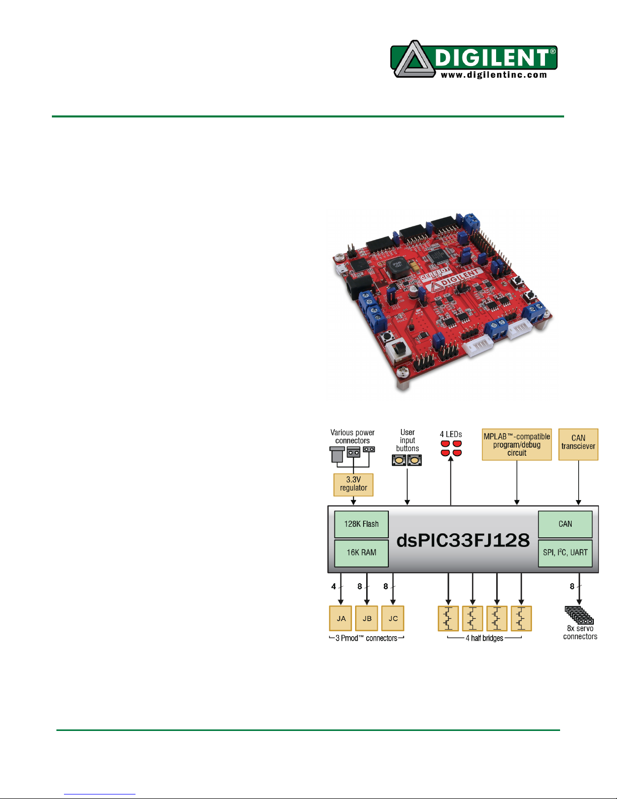
Appendix C: Measured Current Monitoring Data
Half Bridge 1: IMON1
Current
(amps)
0.5
1.5
2.5
3.5
4.5
5.5
0
1
2
3
4
5
6
Voltage
(volts)
0.997
1.11
1.213
1.318
1.424
1.531
1.638
1.747
1.856
1.969
2.084
2.2
2.321
Current
Trip 5.99A
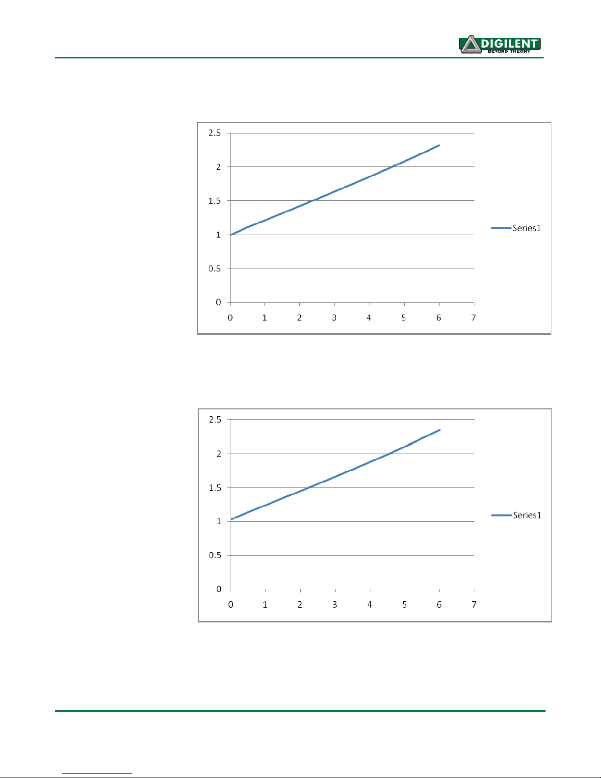
Half Bridge 2: IMON2
Current
(amps)
0.5
1.5
2.5
3.5
4.5
5.5
0
1
2
3
4
5
6
Voltage
(volts)
1.028
1.139
1.242
1.348
1.45
1.556
1.662
1.77
1.88
1.99
2.106
2.223
2.344
Current
Trip 5.87
www.digilentinc.com page 20 of 21
Copyright Digilent, Inc. All rights reserved. Other product and company names mentioned may be trademarks of their respective owners.
Page 21

Cerebot MC7 Reference Manual
Over
Over
Half Bridge 3: IMON3
Current
(amps)
0.5
1.5
2.5
3.5
4.5
5.5
0
1
2
3
4
5
6
Voltage
(volts)
1.003
1.113
1.218
1.326
1.43
1.537
1.644
1.752
1.861
1.973
2.092
2.205
2.328
Current
Trip 5.95
Half Bridge 4: IMON4
Current
(amps)
0.5
1.5
2.5
3.5
4.5
5.5
0
1
2
3
4
5
6
Voltage
(volts)
0.967
1.077
1.181
1.282
1.389
1.493
1.6
1.707
1.816
1.926
2.039
2.158
2.278
Current
Trip 6.15
www.digilentinc.com page 21 of 21
Copyright Digilent, Inc. All rights reserved. Other product and company names mentioned may be trademarks of their respective owners.
Page 22

Mouser Electronics
Authorized Distributor
Click to View Pricing, Inventory, Delivery & Lifecycle Information:
Digilent:
310-025P
 Loading...