

Page 1
OOrrbbiitt BBoooosstteerrPPaacckk™™ RReeffeerreennccee
MMaannuuaal
l
Revision: June 5, 2013
Note: This document applies to REV A of the board.
Overview
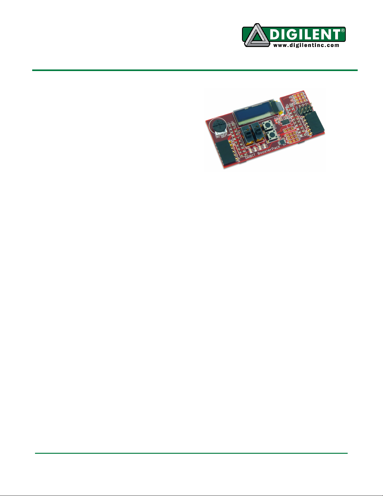
The Digilent Orbit BoosterPack™ is an
add-on board for the Texas Instruments
Stellaris® LaunchPad microcontroller
evaluation kit. The Orbit greatly expands
the input/output capabilities of the
LaunchPad, as well as introducing Digilent
Pmod™ expansion connectors.
Features Include:
• two 1x6 Digilent Pmod™
connectors
• 3-axis accelerometer
• 256 Kbit I2C EEPROM
• I2C temperature sensor
• 128x32 pixel OLED display
• analog potentiometer
Orbit BoosterPack Hardware
Description
Introduction
The following gives a basic description of the
input/output hardware contained in the Orbit
BoosterPack and how to use it. Refer to
Appendix A for a table showing pin definitions.
OLED Graphic Display
The Orbit board provides a 128x32 pixel,
organic LED (OLED), graphic display panel.
The graphic display panel used is the
WiseChip/Univision UG-23832HSWEG04. This
display uses the Soloman Systech SSD1306
display controller.
The UG2832 has a power on/power off
sequence that should be followed. Failure to
follow the power on/power off sequence can
shorten the life of the display. The Orbit
provides two FETs for software control of the
two power supplies for the display. The
1300 NE Henley Court, Suite 3
Pullman, WA 99163
(509) 334 6306 Voice | (509) 334 6300 Fax
VDD_OLED control is used to turn on/off the
power to the logic of the display. The
VBAT_OLED control is used to turn on/off
power to the OLED display itself. These two
pins have pull-up resistors to turn off their
respective power supplies when not being
driven. The pins are made to be outputs and
are driven low to turn on the power supplies.
Power on sequence:
Apply power to VDD
Send Display Off command
Initialize display to desired operating mode
Clear screen
Apply power to VBAT
Delay 100ms
Send Display On command
Power off sequence:
Send Display Off command
Power off VBAT
Delay 100ms
Power off VDD
The display has a D/C pin (display or
command select) that is used to determine
whether bytes sent to the display are
interpreted as commands or as display data.
The D/C pin is driven high for display buffer
access and is driven low for command access.
This pin is shared with VBUS detection on the
LaunchPad. If VBUS is present, the pull-down
resistor acts as a pull-up resistor in conjunction
Doc: 6032-502-000 page 1 of 4
Copyright Digilent, Inc. All rights reserved. Other product and company names mentioned may be trademarks of their respective owners.
Page 2

Orbit BoosterPack Reference Manual
with resistor 6 (R6) on the LaunchPad. Please
see the note in the Orbit BoosterPack
Schematic available from www.digilentinc.com.
The D/C pin is also a non-maskable interrupt
(NMI) pin on the LaunchPad, and is “locked”
on the device’s power-up. In order to unlock
the D/C pin to be used as a general purpose
output, 0x4C4F434B must be written to
GPIOLOCK register. For more information,
please see the LM4F120H5QR Datasheet at:
www.ti.com.
The RES pin is used to reset the SG1306
display controller. The RES pin is driven low
for reset and driven high for normal operation.
The low-going reset pulse must be a minimum
of 3µs (microseconds) for the display controller
to reset correctly.
The UG2832 is a serial device that is accessed
using SPI. It is however, a write-only device. It
is not possible to read back either the display
buffer contents or any kind of status from the
panel. The maximum SPI clock frequency
supported by the UG2832 is 10MHz.
Digilent has a library for use with the Orbit
BoosterPack that provides functions for
initializing the display and rendering simple text
and graphics onto the display. This library can
be used as is or as a starting point for a more
sophisticated graphics library and is available
at www.digilentinc.com.
Digilent Pmod™ Connectors
Two 1x6 pin female Digilent Pmod connectors
are provided for functional expansion of the
Orbit BoosterPack. They are labeled JA and
JB respectively. Header JA has signals routed
to the Synchronous Serial Interface (SSI)
peripheral on the LaunchPad. These signals
can be used with Pmods that use standard 3 or
4 wire SPI communication protocol.
Discrete Digital I/O Devices
Pushbuttons: There are two pushbutton
switches labeled BTN1 and BTN2. A read to
the corresponding GPIODATA register bits will
return a ‘0’ when the button is released and a
‘1’ when the button is pressed.
Slide Switches: There are two slide switches
labeled SW1 and SW2. A read to the
corresponding GPIODATA register bits will
return a ‘0’ when a switch is down (toward the
LEDs) and
a ‘1’
when a switch is up (toward
the OLED display).
LEDs: There are four LEDs, labeled LD1 –
LD4. An LED will be illuminated when the
corresponding GPIODATA register bit is set to
a
‘1’
(given the corresponding direction bit has
been set in the GPIODIR registers) and off
when set to a
‘0’
.
I2C Bus
The I2C bus from the LaunchPad
microcontroller board is brought onto the Orbit
BoosterPack. There are three I2C devices on
the board: a 256 Kbit EEPROM, a temperature
sensor, and an accelerometer. In addition,
there is a connector for taking the I2C bus off of
the board to connect to additional external I2C
devices.
I2C Connector: Connector J5 can be used to
extend the I2C bus off of the board to connect
to additional external I2C devices. J5 is a
standard 2x4 pin header connector with 0.100”
spaced pins. It provides access to the I2C
signals, SCL and SDA, plus VCC3V3 and
GND. The VCC3V3 can be used to power
external I2C devices.
The I2C bus uses open collector drivers to
allow multiple devices to drive the bus signals.
This means that pull-up resistors must be
provided to supply the logic high state for the
signals. The Orbit BoosterPack provides 2.2 Kohm pull-up resistors. Generally, only one set
of pull-up resistors are used on the bus.
Digilent has several small I/O modules
available that can be connected using the I2C
connector. These include a 4-channel, 12-bit
A/D converter, serial character LCD panel, 3-
www.digilentinc.com page 2 of 4
Copyright Digilent, Inc. All rights reserved. Other product and company names mentioned may be trademarks of their respective owners.
Page 3

Orbit BoosterPack Reference Manual
axis gyroscope, real-time clock/calendar, and
I/O expander.
EEPROM: A 256Kbit (32Kbyte), I2C EEPROM
is provided using a Microchip 24LC256. This
EEPROM, IC3, is located on the bottom side of
the board.
The seven bit I2C device address for the
EEPROM is ‘1 0 1 0 A2 0 0’, where A2 is an
external pin. Pin A2 is pulled high through a 10
K-ohm resistor and a cuttable trace at JP7.
Therefore, the ‘as-is’ seven bit I2C device
address for the EEPROM is ‘1010100’, or
0x54. Cutting the trace between pins 1 and 2
of JP7 and loading a two-pin header with a
shorting block on pins 2 and 3 of JP7 will make
the 10 K-ohm resistor acts as pull-down. In this
case, A2 must be set to ‘0’ in software.
For complete technical documentation on the
24LC256, refer to the data sheet available from
www.microchip.com.
Temperature Sensor: A digital temperature
sensor is provided using a Microchip TCN75A
2-Wire Serial Temperature Sensor. The
temperature sensor, IC4, is an I2C device, and
is located next to BTN1.
The TCN75A is rated for an accuracy of +/-1ºC
and has selectable resolution from 0.5ºC down
to 0.0625ºC. The seven bit device address is
‘1001111’, or 0x4F. Note that the last three bits
set to ‘1’ because external pins A2, A1, and A0
are pulled high by 10 K-ohm resistors and
cuttable traces at JP2, JP4, and JP6.
The TCN75A provides an alert output that can
be programmed for various functions.
For complete technical documentation on the
TCN75A, refer to the data sheet available at
www.microchip.com.
Accelerometer: A 3-axis accelerometer is
provided using an Analog Devices ADXL345.
This accelerometer, IC2, is located to the right
of BTN2. The silkscreen shows the axis
configuration.
The 7 bit I2C device address for the
accelerometer is ‘0011101’, or 0x1D.
The ADXL345 has two output pins for setting
configurable interrupts, which include activity,
inactivity, and DATA_READY.
For complete technical documentation on the
ADXL345, refer to the data sheet available at
www.analog.com.
Potentiometer
A potentiometer (pot) is provided on the board
to be used as an analog signal source or
analog control input. The pot is a 1 K-ohm
trimmer pot connected between the VCC3V3
supply and ground. The wiper of the pot is
connected to analog input AIN0.
www.digilentinc.com page 3 of 4
Copyright Digilent, Inc. All rights reserved. Other product and company names mentioned may be trademarks of their respective owners.
Page 4

Orbit BoosterPack Reference Manual
Connector
Pin #
Port
Func
tion Description
Notes
J1 1 - VCC3V3
Power supply
J1 2 PB5 LD4 User LED
J1 3 PB0 JB_03/RX
Pmod connector B pin 3/Rx
UART1
J1 4 PB1 JB_02/TX
Pmod connector B pin 2/Tx
UART1
J1 5 PE4 INT2_ACL
Accelerometer Interrupt Output
J1 6 PF5 /RES_OLED
OLED r
eset
J1 7 PB4 INT1_ACL
Accelerometer Interrupt Output
J1 8 PA5 JA_02/MOSI
Pmod Connector A pin 2/Serial Out
SSI0
J1 9 PA6 SW2
Slide switch
J1 10 PA7 SW1
Slide switch
J2 1 - GND
Ground
J2 2 PB2 SCL I2C clock
I2C0
J2 3 PE0 BTN2
Push button
J2 4 - - - Not connected
J2 5 - - - Not connected
J2 6 - - - Not connected
J2 7 - - - Not connected
J2 8 PA4 JA_03/MISO
Pmod Connector A pin 3/Serial In
SSI0
J2 9 PA3 JA_01/SS
Pmod Connector A pin 1/Slave Select
SSI0
J2 10 PA2 JA_04/SCK
Pmod Connector A
pin 4/Serial Clock
SSI0
J3 1 - - - Not connected
J3 2 - GND
Ground
J3 3 PD0 SCK_OLED
OLED serial clock
SSI3/SSI1
J3 4 PD1 /CS_OLED
OLED chip select
SSI3/SSI1
J3 5 PD2 BTN1
Push button
J3 6 PD3 SDI_OLED
OLED serial data in
SSI3/SSI1
J3 7 PF1 VBAT_O
LED OLED VBAT enable
J3 8 PE2 VDD_OLED
OLED VDD enable
J3 9 PE3 AIN Potentiometer
AIN0
J3 10 - - - Not connected
J4 1 - - - Not connected
J4 2 - - - Not connected
J4 3 PB3 SDA I2C data
I2C0
J4 4 PF0 JB_04/RTS
Pmod connector B pin 4/Request to
UART1
J4 5 PF1 JB01/CTS
Pmod connector B pin 1/Clear to
UART1
J4 6 PC6 LD1 User LED
J4 7 PC7 LD2 User LED
J4 8 PD6 LD3 User LED
J4 9 PD7 /DC_OLED
OLED data/command select
J4 10 - Not connected
Appendix A: Orbit BoosterPack Pinout Table
#
and Bit
www.digilentinc.com page 4 of 4
Copyright Digilent, Inc. All rights reserved. Other product and company names mentioned may be trademarks of their respective owners.
Send
Send
 Loading...