

Page 1
1300 Henley Court
Pullman, WA 99163
509.334.6306
www.digilentinc.com
Digilent myProto™ Reference Manual
Revised November 14, 2014
DOC#: 6002-502-007
Copyright Digilent, Inc. All rights reserved.
Other product and company names mentioned may be trademarks of their respective owners.
Page 1 of 2
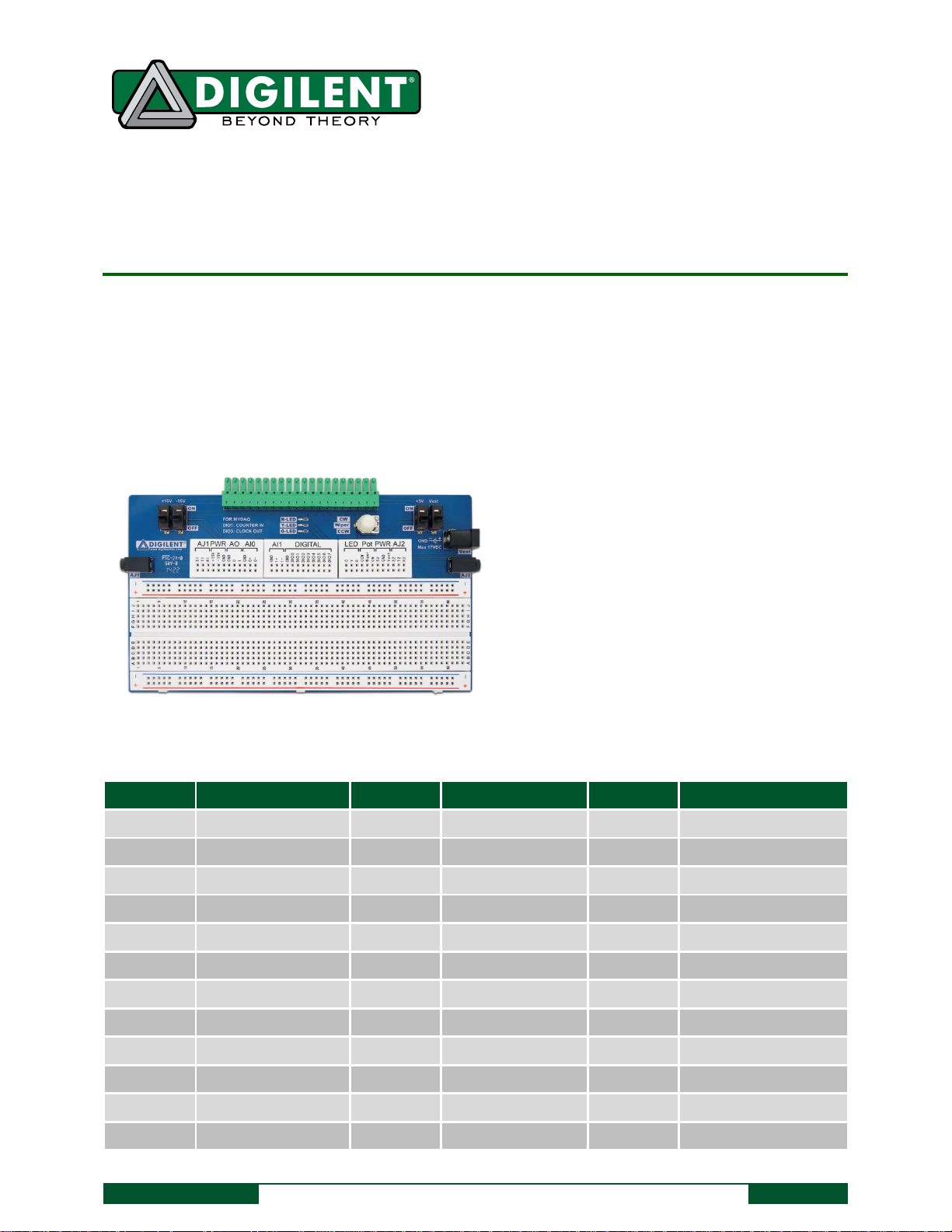
The Digilent myProto board.
Solderless Breadboard
All myDAQ signals accessible from breadboards
3 onboard user LEDs
1 10K Potentiometer
2 Audio Jacks
External power connector for breadboard
circuits
Switches on all power supplies
Pin
Function
Pin
Function
Pin
Function
AJ1 S1
Audio Jack 1 Sleeve
AJ2 T2
Audio Jack 2 Tip
AO 1
Analog Out Pin 1
AJ1 T1
Audio Jack 1 Tip
AJ2 R2
Audio Jack 2 Ring
AI0 GND
Analog In Ground
AJ1 R1
Audio Jack 1 Ring
PWR 5V
myDAQ +5V supply
AI0 0+
Analog In Ch0+
PWR +15V
myDAQ +15V supply
PWR GND
Ground
AI0 0-
Analog In Ch0-
PWR -15V
myDAQ -15V supply
PWR Vext
From Vext Jack
AI1 GND
Analog In Ground
PWR GND
Ground
AO GND
Ground
AI1 1+
Analog In Ch1+
AJ2 S2
Audio Jack 2 Sleeve
AO 0
Analog Out Pin 0
AI1 1-
Analog In Ch1-
DIG GND
Digital GND
DIG DIO4
Digital I/O 4
LED Y
Yellow LED
DIG DIO0
Digital I/O 0
DIG DIO5
Digital I/O 5
LED R
Red LED
DIG DIO1
Digital I/O 1
DIG DIO6
Digital I/O 6
Pot CCW
Pot Counter-CW
DIG DIO2
Digital I/O 2
DIG DIO7
Digital I/O 7
Pot Wiper
Pot Wiper
DIG DIO3
Digital I/O 3
LED G
Green LED
Pot CW
Pot CW
Table 1. Digilent myProto signals.
Overview
The Digilent myProto accessory board for NI myDAQ attaches directly to the myDAQ and brings all myDAQ signals
to breadboard connections where they can be easily accessed using simple jumper wires. The myProto also
includes several additional useful I/O devices. Signal names on the myProto breadboards indicate which myDAQ
signals and onboard devices are attached to which breadboard pins. All Ground connections on the myProto
breadboards are connected into a single Ground node on the myProto device.
Page 2
Digilent myProto™ Reference Manual
Copyright Digilent, Inc. All rights reserved.
Other product and company names mentioned may be trademarks of their respective owners. 374542A-01
Page 2 of 2
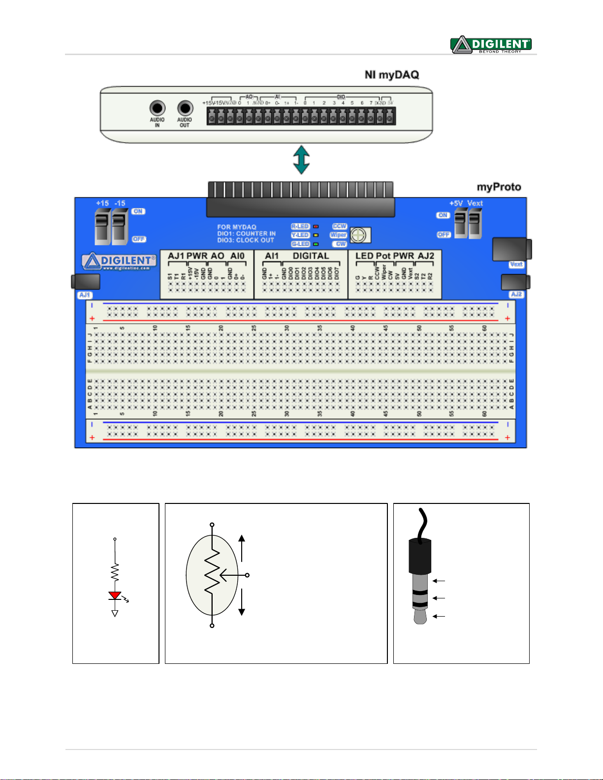
(S) Sleve (Ground)
(R) Ring (Right)
(T) Tip (Left)
CCW
CW
Wiper
When Pot turned CCW,
wiper approaches CCW
pin; R
W-CCW
decreases
and R
W-CW
increases
When Pot turned CW,
wiper approaches CW
pin; R
W-CW
decreases
and R
W-CCW
increases
10KW
LED G, Y, R
390 W
LED Circuit Potentiometer Circuit Audio Jack Connections
Figure 1. Connecting Digilent myProto to the NI myDAQ.
Figure 2. Digilent myProto circuits and breadboard device connections.
 Loading...