

Page 1
1300 Henley Court
Pullman, WA 99163
509.334.6306
www.digilentinc.com
PmodRS485™ Reference Manual
Revised November 10, 2014
This manual applies to the PmodRS485 rev. B
DOC#: 502-310
Copyright Digilent, Inc. All rights reserved.
Other product and company names mentioned may be trademarks of their respective owners.
Page 1 of 3
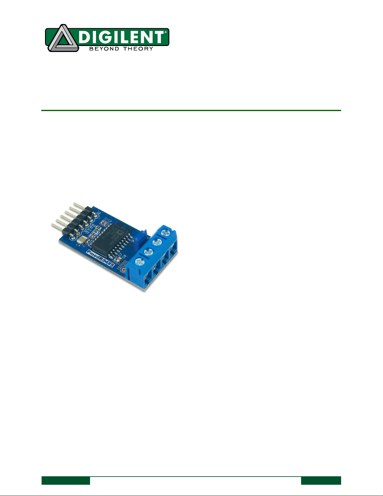
The PmodRS485.
- Isolated RS-485 / RS-422 interfaces
- 16Mbps maximum data rate
- Connect up to 256 nodes on one bus
- Differential Half or full-duplex communication
- Operates with 5V or 3.3V input voltage and digital
signal levels
- +/- 15kV ESD protection
- Thermal shutdown protection
Features include:
Overview
The Digilent PmodRS485 uses the ADM2582E from Analog Devices to provide signal and power isolation for high
speed communication lines utilizing RS-485 communication protocol. The PmodRS485 electronically isolates
devices up to +/- 15kV allowing for peace of mind while combining high voltage hardware with Digilent
microcontroller and FPGA system boards.
1 Functional Description
Basic usage of the PmodRS485 is to facilitate RS-485 and RS-422 serial communication protocols between devices
in environments with high electrical noise. The PmodRS485 can operate at half or full duplex modes with
differential paired signals while providing electrical isolation from other devices.
The PmodRS485 easily interfaces with Digilent Pmod headers and will operate at 3.3V and 5.0V, allowing for
connections to a wide variety of hardware. The controlling hardware can then communicate with devices using
standard serial communication protocols, such as UART.
Page 2
PmodRS485™ Reference Manual
Copyright Digilent, Inc. All rights reserved.
Other product and company names mentioned may be trademarks of their respective owners.
Page 2 of 3
RS485
JP1
Z
Y
A
B
RS485
JP1
Z
Y
A
B
RS485
JP1
Z
Y
A
B
RS485
RS485
JP1
Z
Y
A
B
RS485
Shorted jumper
Not Shorted Jumper
RS485
Transceiver
RE
DE
TXD
RXD
GND
VCC
JP1
Y-output
Z-output
B-input
A-input
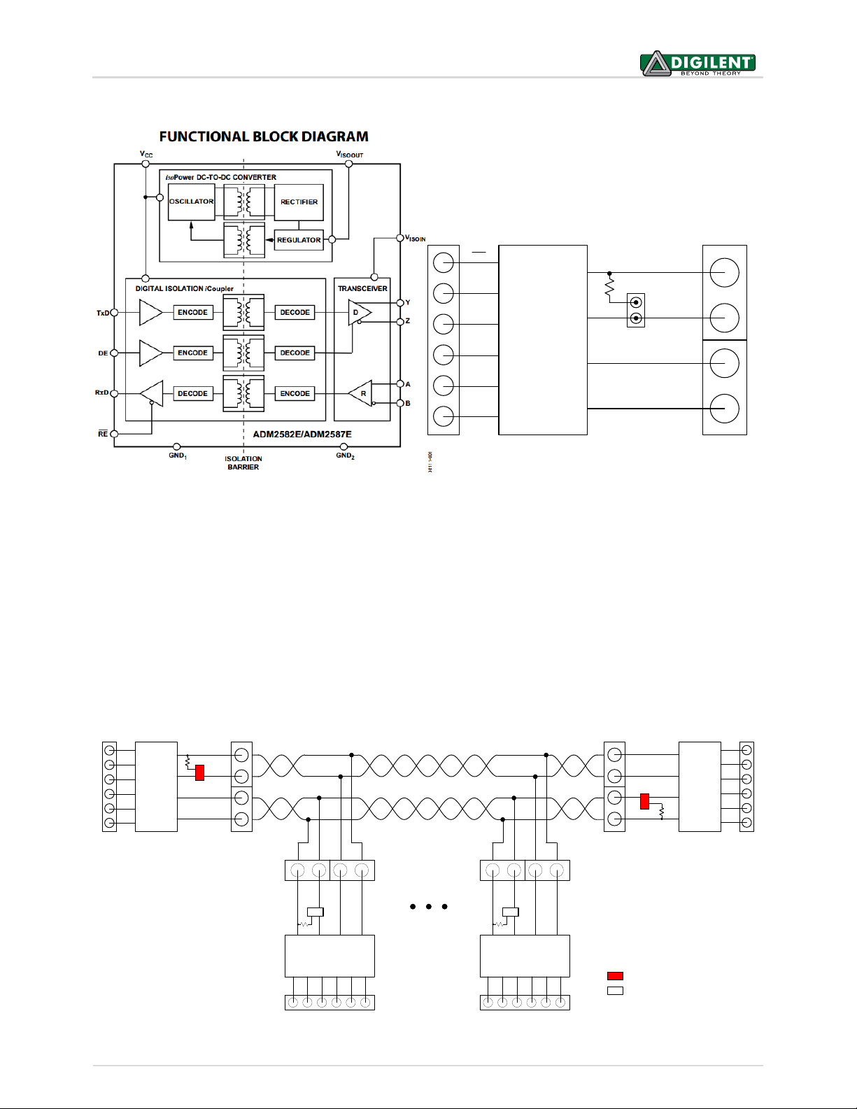
Figure 1. Functional block diagrams of PmodRS485.
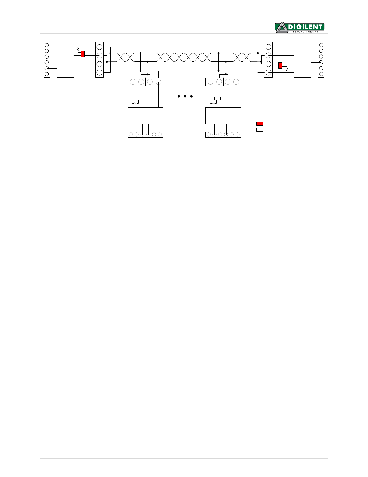
Multiple PmodRS485 devices can be chained together up to 256 nodes in total. When two PmodRS485s are
connected, JP1 should be loaded on both devices. When more than two PmodRS485s are connected, JP1 should
only be loaded on the two devices at the terminating ends of the wire, and stubs off of the main line should be
kept as short as possible (see Figs. 2 & 3 below).
The PmodRS485 has two control signals: receiver enable (RE) and driver enable (DE). RE enables the receiver
module when driven low, and disables it when driven high. DE has the opposite polarity and enables the driver
module when driven high, and disables it when driven low.
For comprehensive electrical characteristics of this device, refer to the ADM2582E datasheet available from Analog
Devices.
Figure 2. Full-duplex communication.
Page 3
PmodRS485™ Reference Manual
Copyright Digilent, Inc. All rights reserved.
Other product and company names mentioned may be trademarks of their respective owners.
Page 3 of 3
RS485
JP1
Z
Y
A
B
RS485
RS485
JP1
Z
Y
A
B
RS485
Shorted jumper
Not Shorted Jumper
RS485
JP1
Z
Y
A
B
RS485
JP1
Z
Y
A
B
Figure 3. Half-duplex communication.
 Loading...