

Page 1
1300 Henley Court
Pullman, WA 99163
509.334.6306
www.digilentinc.com
PmodTMP3 Reference Manual
Revised October 15, 2013
This manual applies to PmodTMP3 RevA
DOC#: 502-287
Copyright Digilent, Inc. All rights reserved.
Other product and company names mentioned may be trademarks of their respective owners.
Page 1 of 3
PmodTMP3
Programmable 9-bit to 12-bit resolution
Typical accuracy of ±1°C
2-wire, I
2
C compatible interface with 8
selectable addresses
30ms to 240ms typical conversion times
2.7V to 5.5V operating voltage range
Programmable temperature alert
Overview
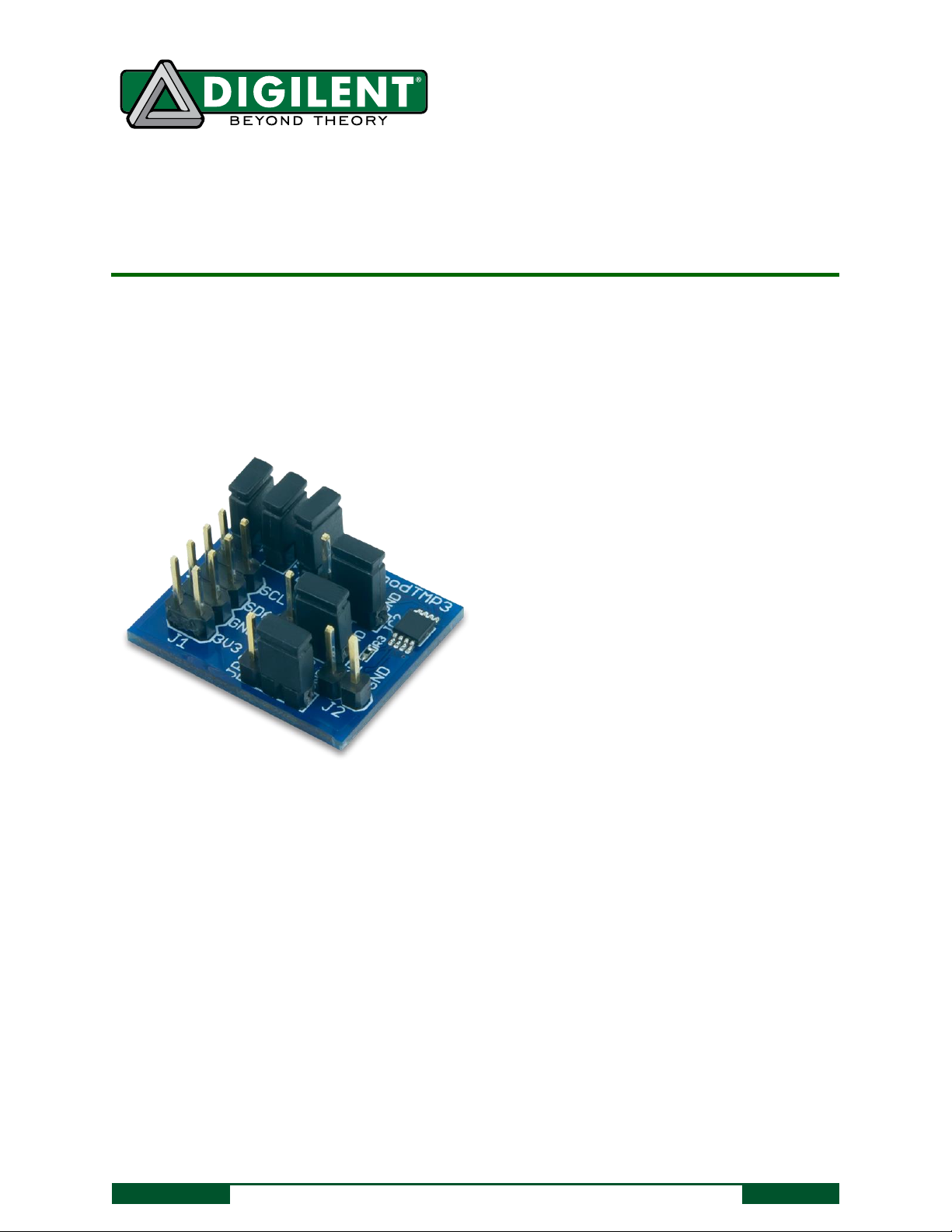
The Digilent PmodTMP3 is a temperature sensor built around the Microchip TCN75AVUA.
1 Functional Description
The PmodTMP3 uses an 8-pin connector that allows for communication via I2C and provides pins to daisy-chain the
PmodTMP3 to other I2C devices. The PmodTMP3 also provides three 3-pin headers for selecting the I2C address of
the chip, and one 2-pin header for controlling external devices based upon temperature thresholds defined by the
user in software. Temperature data measured by the device is formatted in two’s compliment and may be
programmed for a resolution of 9-bits to 12-bits through the configuration register on the TCN75AVUA.
Page 2
PmodTMP3 Reference Manual
Copyright Digilent, Inc. All rights reserved.
Other product and company names mentioned may be trademarks of their respective owners.
Page 2 of 3
Pin
Signal
Description
1, 2
SCL
I2C Clock
3, 4
SDA
I2C Data
5, 6
GND
Power Supply Ground
7, 8
3V3
Power Supply (3.3V)
JP4
JP5
Pull-Up State
Open
Open
Pull-ups disabled
Shorted
Shorted
Pull-ups enabled
2 I2C Interface
The TCN75AVUA on the PmodTMP3 acts as a slave device using I2C serial communication. To communicate with
the PmodTMP3, the master device must specify a slave address (0x48-0x4F) and a flag indicating whether the
communication is a read (1) or a write (0). This is followed by the actual data transfer. For the TCN75AVUA, the
data transfer should consist of the address of the desired device register followed by the data to be written to the
specified register. To read from a register the master must write the desired register address to TCN75AVUA, then
send an I2C restart condition, and send a read request to the TCN75AVUA.
I2C Interface Connector Signal Description
The I2C interface standard uses two signal lines. These are I2C data (SDA) and I2C clock (SCL). On the TCN75AVUA,
both SDA and SCL are open-drain pins. For communication to be established, these pins must be connected to pullup resistors. The PmodTMP3 has selectable pull-up resistors on jumpers JP4 and JP5. If the master device used to
communicate with the PmodTMP3 does not have pull-up resistors on the SDA and SCL signals, both JP4 and JP5
must be shorted to establish communication via I2C. If the master device already has pull-up resistors, these
jumpers may remain open.
I2C Pull-up Jumper Settings
3 I2C Address Selection
The PmodTMP3 I2C bus can be set to use one of eight valid addresses. The top four bits of the address are fixed,
and the three least significant bits are specified by the states of jumpers JP1, JP2 and JP3. JP1 corresponds to bit
zero of the address, JP2 corresponds to bit one of the address, and JP3 corresponds to bit two of the address. The
address is set by shorting the AX pin on the PmodTMP3 (where X is the bit number) with either 3V3 or GND.
Shorting a jumper in the GND position corresponds to a zero while shorting a jumper in the 3V3 position
corresponds to a one.
Page 3

PmodTMP3 Reference Manual
Copyright Digilent, Inc. All rights reserved.
Other product and company names mentioned may be trademarks of their respective owners.
Page 3 of 3
JP3
JP2
JP1
Address
GND
GND
GND
0x48 (0b1001000)
GND
GND
3V3
0x49 (0b1001001)
GND
3V3
GND
0x4A (0b1001010)
GND
3V3
3V3
0x4B (0b1001011)
3V3
GND
GND
0x4C (0b1001100)
3V3
GND
3V3
0x4D (0b1001101)
3V3
3V3
GND
0x4E (0b1001110)
3V3
3V3
3V3
0x4F (0b1001111)
Addresses
4 Open Drain Output
The PmodTMP3 provides a single open-drain header for controlling external devices based on current temperature
thresholds. When the ambient temperature surpasses the value contained in the T
signaled on the AL pin of header J2. The alert may be active low or high based upon the configuration of the device
and the state of JP6. Shorting JP6 pulls up the AL pin by a 2.2kOhm resistor when it is not driven by the device. The
alert signal may be configured to act as a comparator output or as an interrupt.
register, an alert can be
SET
5 Quickstart Operation
When the PmodTMP3 is powered up, the onboard TCN75AVUA is in a mode that may be used as a temperature
sensor without any initial configuration. The default mode of operation provides a continuous conversion, 9-bit
resolution, and an active-low, comparator output alert. On power-up, the TCN75AVUA register pointer points to
the Temperature register, so a two byte read without specifying a register will read the value of the temperature
from the device from most significant byte (MSB) to least significant byte (LSB). For 9-bit resolution, the
temperature in degrees Celsius may be calculated as a floating point value by shifting the temperature register
data to the right seven bits and multiplying by 0.5.
For more information on the TCN75AVUA and reading or writing to other registers on the device, please refer to
the TCN75AVUA datasheet available at www.microchip.com.
 Loading...