

Page 1
1300 Henley Court
Pullman, WA 99163
509.334.6306
www.digilentinc.com
PmodALS™ Reference Manual
Revised January, 21 2015
This manual applies to the PmodALS rev. A
DOC#: 502-286
Copyright Digilent, Inc. All rights reserved.
Other product and company names mentioned may be trademarks of their respective owners.
Page 1 of 2
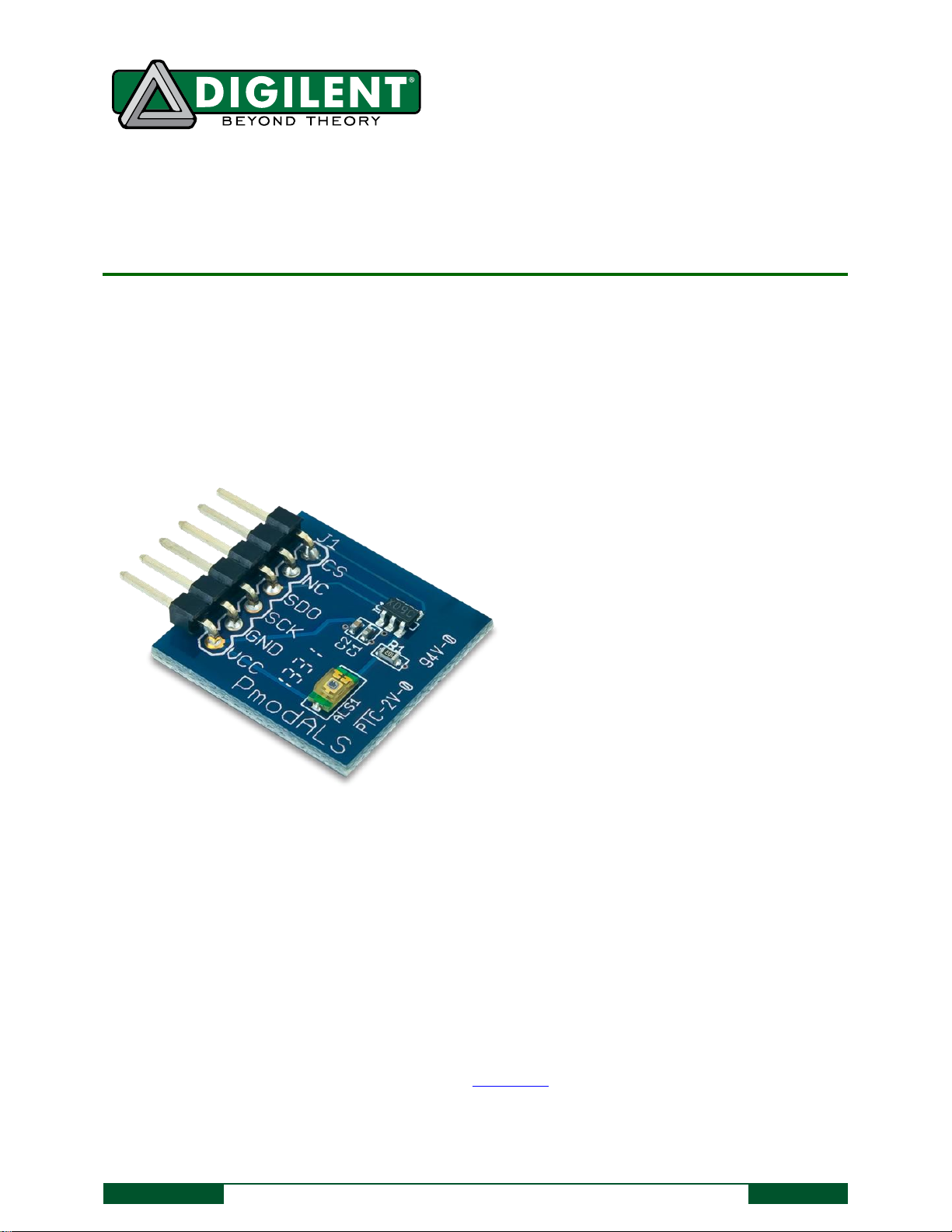
The PmodALS.
3-wire SPI™ communication interface
8-bit resolution
Features include:
Overview
The Digilent PmodALS demonstrates light-to-digital sensing through a single ambient light sensor. Digilent
engineers designed this Pmod around the Texas Instrument's ADC081S021 analog-to-digital converter and the
Vishay Semiconductor's TEMT6000X01.
1 Functional Description
The PmodALS utilizes a single ambient light sensor (ALS) for user input. The amount of light the ALS is exposed to
determines the voltage level passed into the ADC, which converts it to 8 bits of data. A value of 0 indicates a low
light level and a value of 255 indicates a high light level.
2 Interfacing with the Pmod
The PmodALS communicates with the host board via the SPI protocol. Since the on-board analog-to-digital
converter is a read-only module, the only wires in the SPI protocol that are required are the Chip Select, Master-InSlave-Out, and Serial Clock lines. The location of each of these lines on the Pmod header are shown in the table
below.
Page 2
PmodALS™ Reference Manual
Copyright Digilent, Inc. All rights reserved.
Other product and company names mentioned may be trademarks of their respective owners.
Page 2 of 2
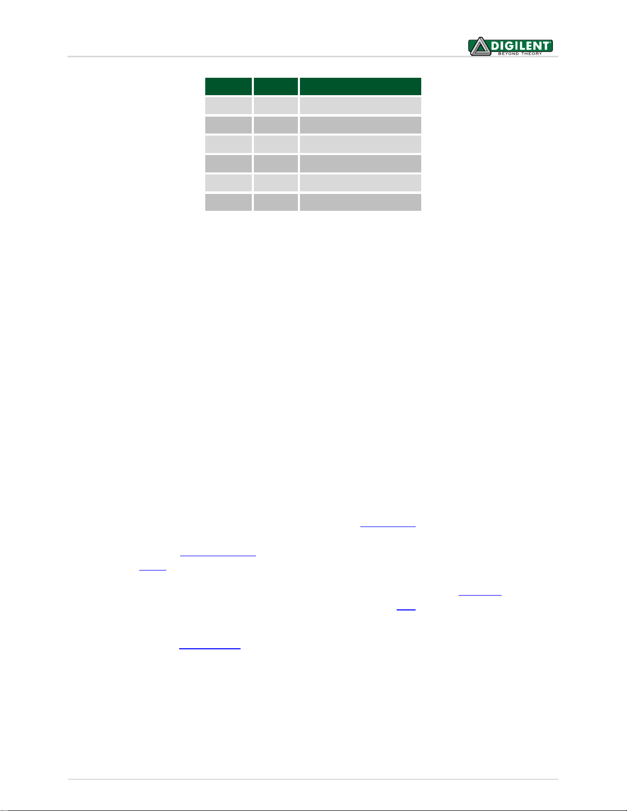
Pin
Signal
Description
1
CS
Chip Select
2
NC
Not Connected
3
SDO
Master-In-Slave-Out
4
SCK
Serial Clock
5
GND
Power Supply Ground
6
VCC
Power Supply
Table 1. Connector J1- Pin Descriptions as labeled on the Pmod.
The PmodALS reports to the host board when the ADC081S021 is placed in normal mode by bringing the CS pin
low, and delivers a single reading in 16 SCLK clock cycles. The PmodALS requires the frequency of the SCLK to be
between 1 MHz and 4 MHz. The bits of information, placed on the falling edge of the SCLK and valid on the
subsequent rising edge of SCLK, consist of three leading zeroes, the eight bits of information with the MSB first,
and four trailing zeroes.
Any external power applied to the PmodALS must be within 2.7V and 5.25V; however, it is recommended that
Pmod is operated at 3.3V.
3 Physical Dimensions
The pins on the pin header are spaced 100 mil apart. The PCB is 0.8 inches long on the sides parallel to the pins on
the pin header and 0.8 inches long on the sides perpendicular to the pin header.
4 Additional Information
The schematics of the PmodALS are available for download from the product page. Additional information about
the ADC, including communication modes and specific timings of the chip, can be found by checking out its
datasheet available from Texas Instruments. Similarly, the datasheet for the ambient light sensor can be found on
the website for Vishay.
More specific information about how to use the PmodALS can be found by checking out our user guide. Example
code demonstrating how to get information from the PmodALS can be found here.
If you have any questions or comments about the PmodALS, feel free to post them under the appropriate section
("Add-on Boards") of the Digilent Forum.
 Loading...