

Page 1
PPmmooddAAMMPP33™™ RReeffeerreennccee MMaannuuaal
Loaded
Unloaded
Loaded
Unloaded
l
Revision: February 20, 2013
Note: This document applies to REV A of the board.
1300 NE Henley Court, Suite 3
Pullman, WA 99163
(509) 334 6306 Voice | (509) 334 6300 Fax
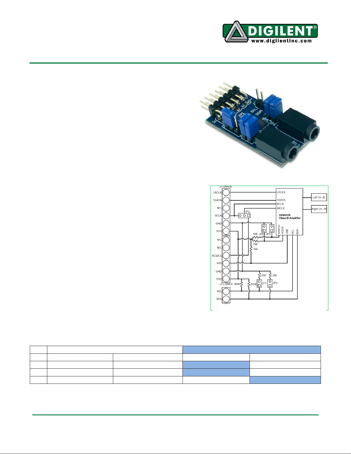
Overview
The Digilent PmodAMP3 features an Analog
Devices SSM2518 2 watt Class-D Audio
Power Amplifier. The module enables the use
of I2S audio protocol or TDM to produce stereo
audio at various sampling frequencies. The
module features configurable digital volume
and dynamic range control via an I2C interface.
Additionally, you may use the AMP3 in a
stand-alone mode that does not require the
use of the I2C interface.
Features Include:
• separate left and right channel 1/8-inch
headphone jacks
• 12-pin header Pmod™ interface connector
• supports common I2S audio formats
• digitally configurable volume control for each channel
• dynamic range control
• standalone mode for systems without I2C interface
• Operates at 3.3 V
Functional Description
Customers may operate the PmodAMP3 in either an I2C
programmable mode or a simple stand-alone mode. The
stand-alone mode is the default setting and can be activated
by clearing the jumper JP5. When the stand-alone mode is
active, the jumpers JP3, JP4, and JP6 allow a simple
hardware configuration of the amplifier. The jumper JP3
configuration determines whether to use Standard or Left
Justified I2S protocol. The jumper JP4 determines if the MCLK
input is 256 or 384 times the audio sampling frequency Fs. The jumper JP6 configures the amplifier to
output at either 0dB or +12dB gain. (See Table 1 for further information.)
JP5 Loaded (I2C Programmable Mode) JP5 Unloaded (Stand-Alone Mode)
Figure 1. Design Layout
JP3 Prohibited Required I2S (Standard) Left Justified
JP4 Prohibited Required 256x Fs 384x Fs
ADDR: 0110100[r/w] ADDR: 0110110[r/w]
JP6
Table 1. Connector Descriptions
Doc: 502-270 page 1 of 2
Copyright Digilent, Inc. All rights reserved. Other product and company names mentioned may be trademarks of their respective owners.
12dB Gain 0dB Gain
Page 2

Digilent Product Name
Note: Both the 0dB and +12dB gain modes are very loud. You should take care to protect both
yourself and your equipment when operating in stand-alone mode. Digilent recommends that you use
the programmable mode and set the gain to -12dB or lower.
Programming Interface
When using the I2C programmable mode, you have to set the jumper JP5 and remove the jumpers
JP3 and JP4. You can use Jumper JP6 to configure the 6th bit of the 7-bit I2C address. You can
program the SSM2518 via the I2C protocol address [0][1][1][0][1][ADDR][0][R/W]. The 8th bit “R/W”
determines the type of I2C transmission and should be set Low for Write and High for Read.
Audio Interface
The PmodAMP3 requires the use of the I2S or TDM audio protocols for operation. The Pmod requires
the LRCLK input to indicate the channel of the audio data presented. The sampling frequency Fs of
the data presented should be the same as the LRCLK frequency. The SSM2518 supports sampling
frequencies from 8 to 96 KHz. The BCLK must present 64 clocks in a single period of the LRCLK, 32
clocks for each phase of the LRCLK. The AMP3 uses the clock to shift data into the SSM2518 in 24bit words.
The SSM2518 requires the use of an MCLK signal as well, which you can generate internally in the
device. However, customers must provide an external reference clock. The PmodAMP3 has a jumper
JP2 which allows you to route the BCLK to the MCLK input. This signal may then be processed
internally by the SSM2518 to generate an appropriate MCLK signal. In addition, you may generate the
MCLK signal externally and provide it to the MCLK-E pin.
Power Supply
The SSM2518 includes an active low Shut Down pin. This pin must be driven high while the device is
in use. The device may be powered down by driving a logic low signal to the pin. The PmodAMP3
includes a 10Kohm pull-up resistor on this pin. However, you must configure the parent system board
I/O to prevent an unknown voltage settling on the pin.
We have designed the PmodAMP3 to work with either Digilent programmable logic or Digilent
embedded control system boards that have 6 or 12-pin header connectors. The AMP3 connects
directly into these header connectors. The PmodAMP3 requires a 3.3V supply voltage to power the
module. All Digilent system boards have a comparable power supply voltage (3.3V) and provide the
necessary power as part of the standard Pmod interface. Digilent system boards that provide Pmod
interface connectors allow jumper selection of the Pmod power supply voltage. Ensure that your
system board has a jumper to provide 3.3V to the module before applying power to the board.
Note: For more information on the PmodAMP3 see the schematic at: www.digilentinc.com. For a
detailed review of the SSM2518, including Input Register data formatting, please refer to the
SSM2518 Data Sheet available at www.analog.com.
www.digilentinc.com page 2 of 2
Copyright Digilent, Inc. All rights reserved. Other product and company names mentioned may be trademarks of their respective owners.
 Loading...