

Page 1
chipKIT™ Motor Shield
Reference Manual
Revision: April 16, 2013
Note: This document applies to REV D of the board.
1300 NE Henley Court, Suite 3
Pullman, WA 99163
(509) 334 6306 Voice | (509) 334 6300 Fax
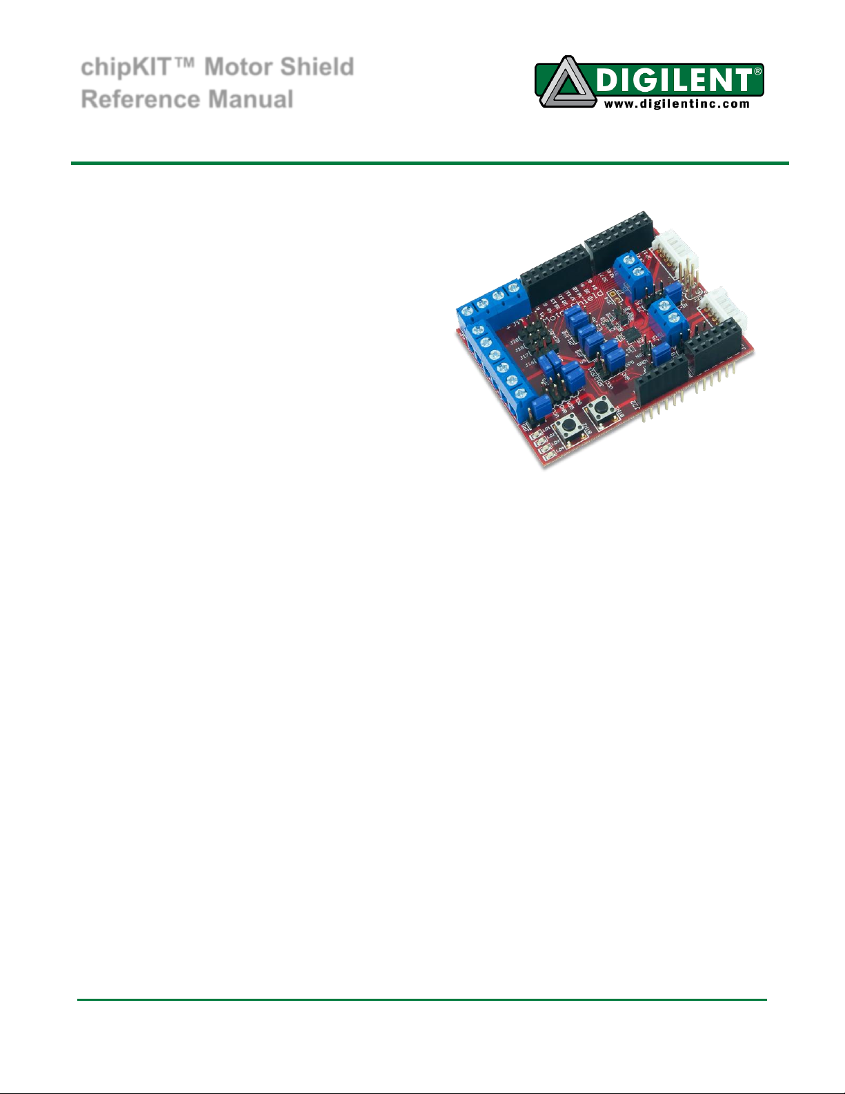
Overview
The chipKIT™ Motor Shield is an expansion
board for use with the chipKIT Uno32 and
chipKIT uC32. It provides additional circuitry
and connectors for the Uno32 and uC32 to
drive various motors types.
The chipKIT Motor Shield is designed to drive
DC motors, servo motors, and stepper motors.
It also provides additional I/O via an I2C I/O
extender.
Features include:
2 DC motor driver channels,
accessible with either a JST 6-pin
connector or a terminal block
2 DC motor encoder input signals for
each DC motor channel
4 servo motor channels
I2C General purpose I/O expander
with 4 LEDs 2 push buttons and 2
user settable jumpers
1 4-wire unipolar stepper motor
channel
Standard chipKIT Shield connectors
Functional Description
The chipKIT Motor Shield is designed to be used with the chipKIT Uno32 or chipKIT uC32 board.
When used with these boards, the microcontroller and shield provide the necessary supporting
hardware and connectors to control most types of small motors. The rest of this document will only
reference the Uno32; however, the shield can also be used with the chipKIT uC32.
The chipKIT Motor Shield has the following connectors:
J1: Power Supply for the DC motor driver
This connector provides power to the DVR8833RTY motor driver for the DC motors. Motor supply
voltage range is 2.7-10.8 V.
Doc: 502-262 page 1 of 8
Copyright Digilent, Inc. All rights reserved. Other product and company names mentioned may be trademarks of their respective owners.
Page 2

chipKIT Motor Shield Reference Manual
J3 & J6: DC motor 6-pin JST connector
These connections provide power and feedback signals for DC motors. The pin-outs are compatible
with the Digilent DC gear-motors.
J5 & J7: DC motor terminal block connector
These connections provide the power supply pin-out for most two wire DC motors.
J2: DC motor driver disable
Shorting these two pins (or driving the NS signal pin low) will put the DC motor driver into sleep mode.
This disables the motor driver and therefore reduces power consumption. This option is useful for low
power applications.
J4: DC motor driver fault indicator
The NF signal will be driven low when there is a fault detected within the DC motor driver. Possible
reasons for fault include overcurrent, overheat, and low voltage.
J8 & J9: DC motor feedback signal headers
Headers for connecting DC motor feedback signals.
J10: Power Supply for Stepper motor
This connector provides power for driving the stepper motor.
J12 & J13: Stepper motor terminal block connectors
These connections are used for driving a stepper motor.
J14: Power Supply for servo motors
This connector provides external power for driving the servo motors. If using this header remove JP6
to ensure that servo power supply is not shorted to the 5 Volt Uno32 power supply.
J11 & J15: Digital Signal Pass-Through Connectors
This connector passes the digital I/O pins on the Uno32 through to the chipKIT Motor Shield.
J21: I2C #1 Daisy Chain Connector
This is a 2x4 pin header connector that provides access to the I2C signals SDA and SCL as well as
power from the 3.3V power bus and ground. This can be used to extend the I2C bus off of the board
and to power external I2C devices. Digilent has cables and a selection of I2C peripheral modules that
can be accessed using this connector.
www.digilentinc.com page 2 of 8
Copyright Digilent, Inc. All rights reserved. Other product and company names mentioned may be trademarks of their respective owners.
Page 3
chipKIT Motor Shield Reference Manual
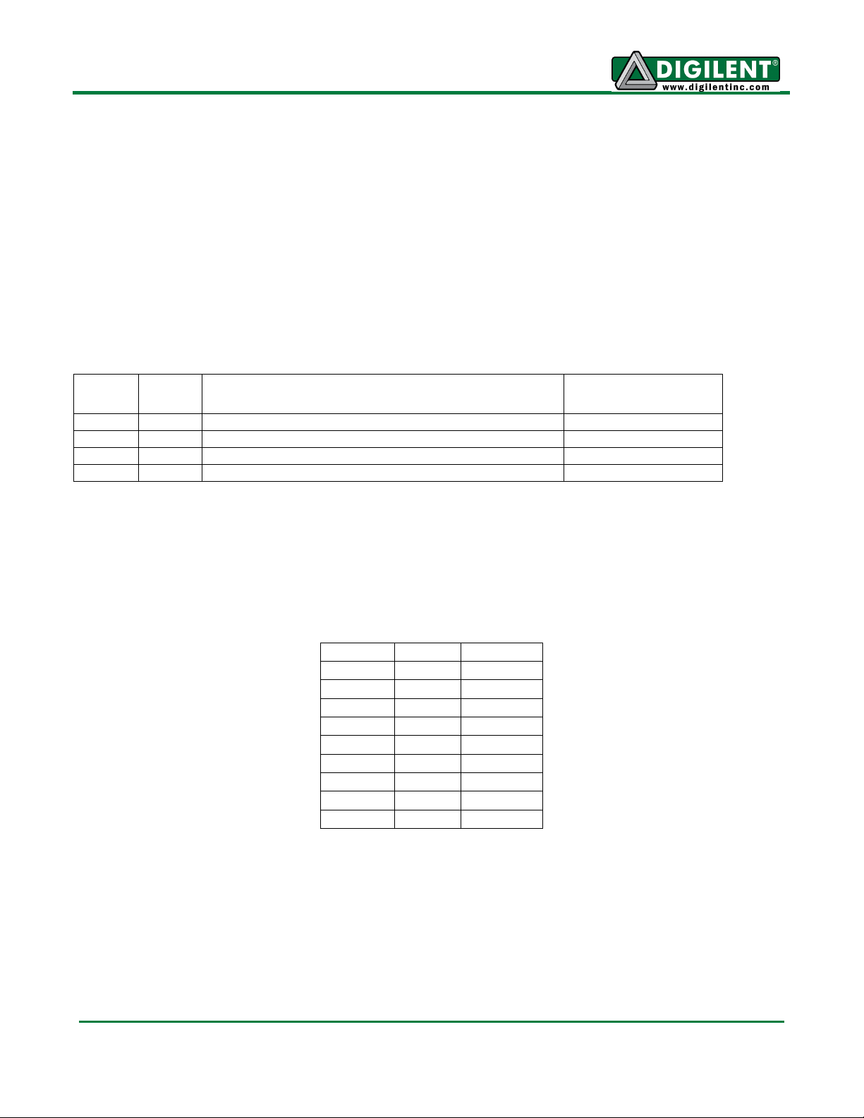
Uno32
Pin #
PIC32
Pin #
Signal
Notes
3
46
Enable1: OC1/RD0
4 59
Direction1: RF1
3/5
46/49
Enable2: OC1/RD0 or OC2/RD1
Select with JP1
4/34
59/53
Direction2: RF1 or PMRD/CN14/RD5
Select with JP2
DIR1
EN1
Result
0 0 Stop
0
1/PWM
Forward
1 0 Stop
1
1/PWM
Reverse
DIR2
EN2
Result
0 0 Stop
0
1/PWM
Forward
1 0 Stop
1
1/PWM
Reverse
J19: Analog Signal Pass-Through Connector
This connector passes the analog input pins on the Uno32 through the chipKIT Motor Shield.
J22: Power Pass-Through Connector
This connector passes the power connector from the Uno32 through the chipKIT Motor Shield, and
powers the chipKIT Motor Shield from the Uno32.
DC Motor Controller
The Motor Shield provides a means to control 2 independent DC motors via a DRV883 dual H-bridge
motor driver. The motor driver must be powered via J1 to operate, voltages between 2.7 and 10.8
volts are acceptable. Each channel is controlled by an “enable” and “direction” signal.
Channel 2 can be set up for identical or independent operation from channel 1 using JP1 and JP2.
PWM levels on enable pins will regulate the speed of the motors. Logic levels on direction pins will
determine the motors rotation direction of the attached DC motors. The chipKIT Uno32 uses a
demultiplexer and pull-down resistors on the inputs to the DRV8833 H-Bridge pins to ensure that the
H-Bridge only works in fast decay mode. Table 1 lists the motor responses that result from various
input combinations.
The DRV8833 chip provides overcurrent protection on the motor drive circuits. Each internal drive
FET is independently monitored for an overcurrent condition and will be shut down internally to protect
the chip. When an overcurrent condition is sensed the chip will shut down the FET with the fault and
then set the NFAULT pin low signaling a fault condition on the chip. The remaining FETs will continue
to operate as normal. When the fault condition is over, the chip will self-reset and return the NFAULT
logic level to logic high. (See Table 2 for connector descriptions.)
www.digilentinc.com page 3 of 8
Copyright Digilent, Inc. All rights reserved. Other product and company names mentioned may be trademarks of their respective owners.
Table 1: Motor Control
Page 4
chipKIT Motor Shield Reference Manual
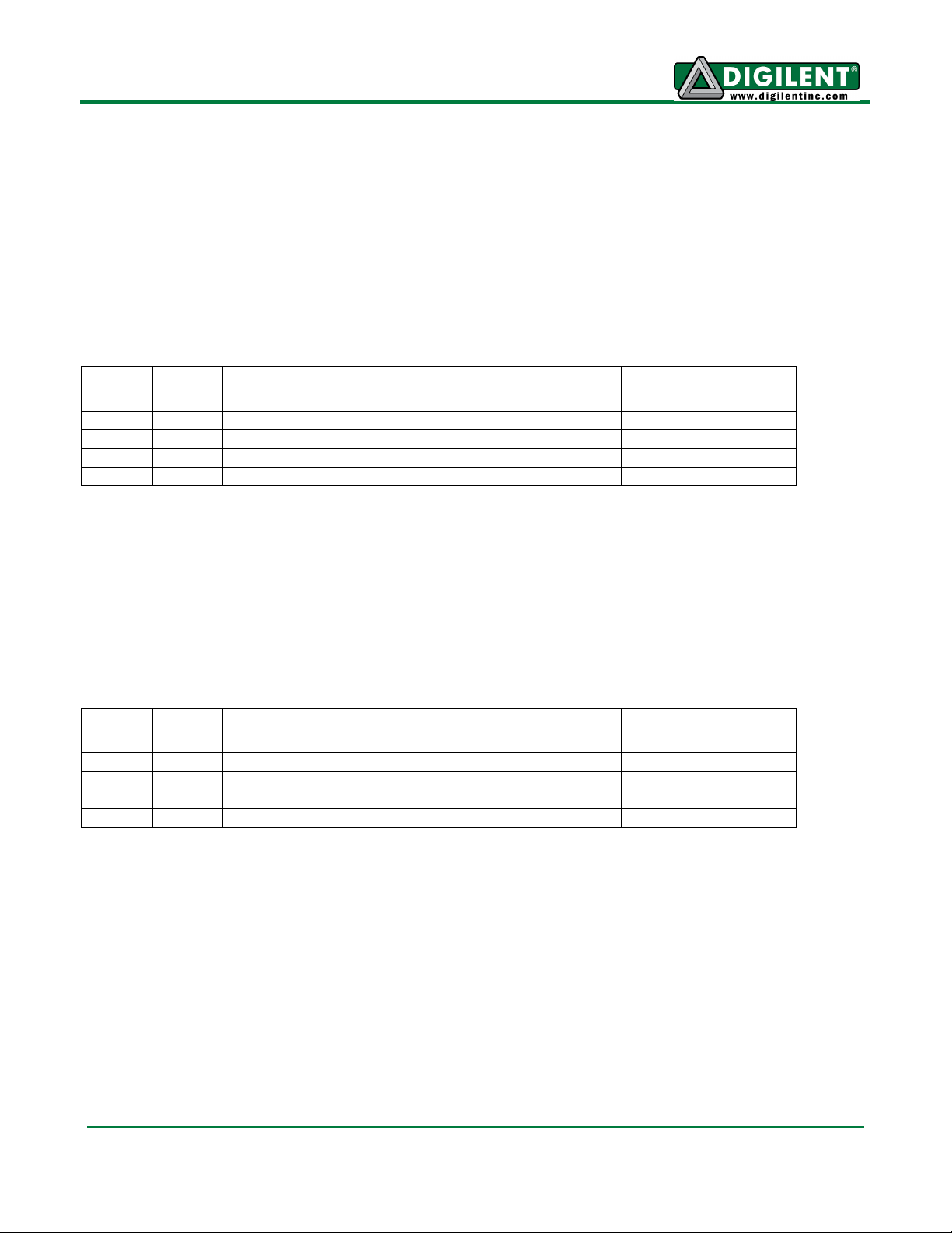
Uno32
Pin #
PIC32
Pin #
Signal
Notes
26
60
A: PMD0/RE0
27
61
B: PMD1/RE1
28
62
C: PMD2/RE2
29
63
D: PMD3/RE3
Uno32
Pin #
PIC32
Pin #
Signal
Notes
30
64
Servo1: PMD4/RE4
J16
31
1
Servo2: PMD5/RE5
J17
32
2
Servo3: PMD6/RE6
J18
33
3
Servo4: PMD7/RE7
J20
There are two Schmitt trigger buffered inputs on connectors J3, J6, J8 and J9 that bring motor speed
feedback signals to the controlling system board. The Digilent motor and gearbox have hall-effect
sensors arranged in a quadrature encoder format. These buffers have 5V tolerant inputs, when
operated at 3.3V.
The quadrature encoder signals are a pair of square waves whose frequency is proportional to motor
rotation speed and with the pulses 90 out of phase. You can determine the motor speed with the
frequency and motor rotation direction by the phase relationship between the two signals.
Stepper Motor Controller
The stepper motor controller has 4 output signals. It is composed of 4 open-drain transistor amplifiers.
The stepper motor driver can be powered by either VIN, or an external power source connected to
J10. If connecting an external power source, JP5 should be removed to prevent shorting the stepper
motor voltages to the input voltage of the chipKIT board.
Servo Motors
The Motor Shield has 4 servo motor connections. They can be powered from VCC5V0 or an external
power source connected to J14. If connecting an external power source, JP6 should be removed. The
voltage of the power source can be measured on analog pin A11 via a resistor divider network (see
the schematic for more details).
I2C Bus and Connectors
The Inter-Integrated Circuit (I2C) Interface provides a medium speed (100K or 400K bps) synchronous
serial communications bus. The I2C interface provides master and slave operation using either 7 bit or
10 bit device addressing. Each device is given a unique address, and the protocol provides the ability
to address packets to a specific device or to broadcast packets to all devices on the bus. Refer to the
Microchip PIC32MX3XX data sheet and the PIC32 Family Reference Manual for detailed information
on configuring and using the I2C interface.
The PIC32MX320 microcontroller on the Uno32 provides for two independent I2C interfaces. The
Motor Shield is designed to provide access to one of these interfaces, I2C #1 (SCL1, SDA1). I2C #1 is
accessed through the standard chipKIT Wire library. Connector J21 provides access to I2C port #1.
www.digilentinc.com page 4 of 8
Copyright Digilent, Inc. All rights reserved. Other product and company names mentioned may be trademarks of their respective owners.
Page 5

chipKIT Motor Shield Reference Manual
Connector J21 can be used to extend the I2C bus off of the board to connect to external I2C devices.
This is a standard 2x4 pin header connector with 0.100” spaced pins. It provides access to the I
2
C
signals, SCL1 and SDA1, plus VCC3V3 and ground. The VCC3V3 can be used to power external I2C
devices.
The I2C bus uses open collector drivers to allow multiple devices to drive the bus signals. This means
that pull-up resistors must be provided to supply the logic high state for the signals. The Motor Shield
provides 2.2Kohm pull-up resistors on I2C #1.
Generally, only one set of pull-ups are used on the bus. Jumpers JP7 and JP8 can be used to disable
the on-board pull-ups on I2C #1 if a different value is needed or some other device on the bus is
providing the pull-ups or if I2C #1 isn’t being used and the pull-ups are interfering with the use of the
pins. The on-board pull-ups are enabled by install shorting blocks on JP7 and JP8. Removing the
shorting blocks disables the pull-ups.
Digilent has several small I/O modules available that can be connected using the I2C connector.
These include a 3-axis accelerometer, 4-channel, 12-bit A/D converter, serial character LCD panel, 3axis gyroscope, and a real-time clock/calendar. The on-board I/O expander is also controlled via I2C
#1.
I/O Expander
The Motor Shield contains an I/O expander module that gives access to 4 LEDs, 2 pushbuttons, and 2
jumper-switches. The I/O expander is controlled via I2C #1. The outputs can be easily controlled using
the Motor Shield MPIDE library.
CHIPKIT and the CHIPKIT Logo are trademarks or registered trademarks of Microchip Technology Incorporated in the
U.S. and other countries, and are used under license.
www.digilentinc.com page 5 of 8
Copyright Digilent, Inc. All rights reserved. Other product and company names mentioned may be trademarks of their respective owners.
Page 6

chipKIT Motor Shield Reference Manual
Uno32
Pin #
PIC32
Pin #
Pin
Signal
Notes
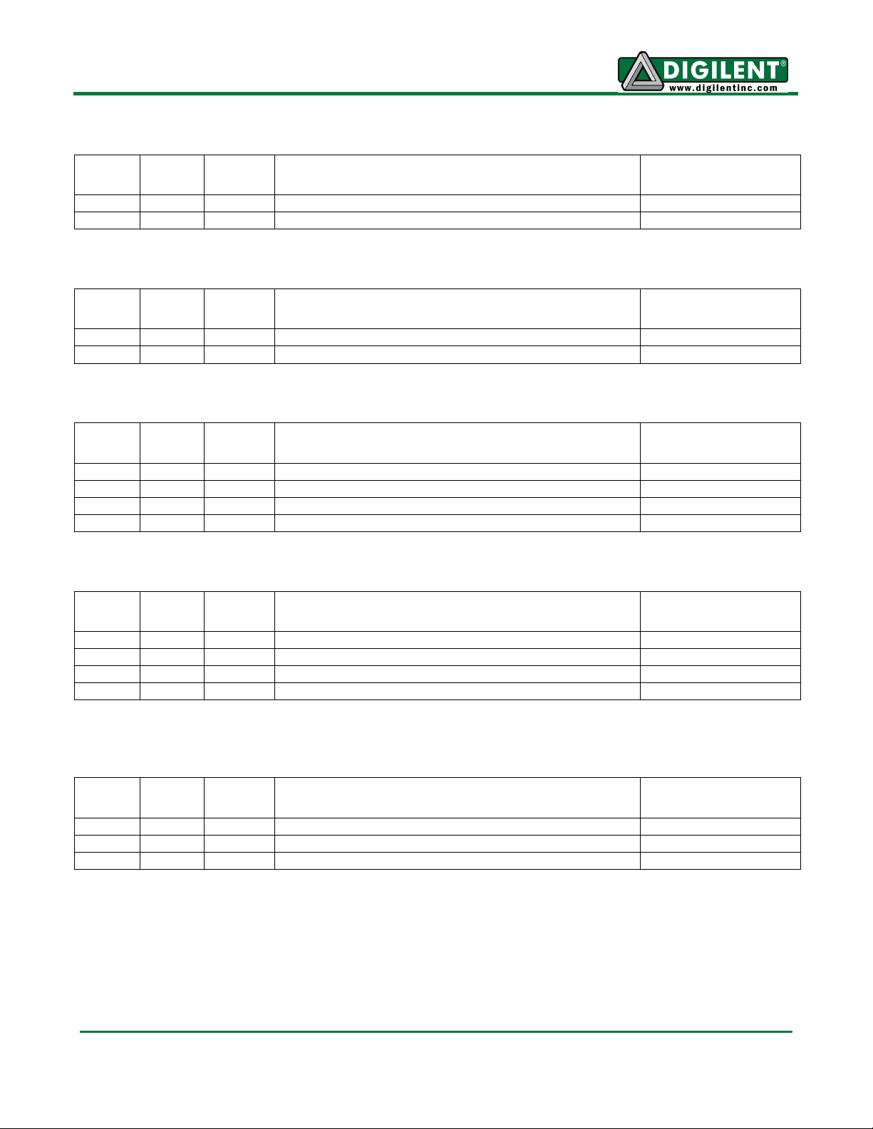
J1-01
VM (motor driver power supply)
2.7-10.8 V
J1-02
GND
Uno32
Pin #
PIC32
Pin #
Pin
Signal
Notes
J2-01
Motor Driver NSLEEP
Pull low to sleep
J2-02
GND
Uno32
Pin #
PIC32
Pin #
Pin
Signal
Notes
J4-01
Motor Driver NFAULT
Goes low on error
J4-02
GND
Uno32
Pin #
PIC32
Pin #
Pin
Signal
Notes
J3-01
SB1-IN J3-02
SA1-IN J3-03
GND J3-04
VCC3V3
J3-05
M1+ J3-06
M1-
Uno32
Pin #
PIC32
Pin #
Pin
Signal
Notes
J6-01
SB2-IN J6-02
SA2-IN J6-03
GND J6-04
VCC3V3
J6-05
M2+
J6-06
M2-
Appendix: chipKIT Motor Shield Pin-out Tables
J1 Pins
J2 Pins
J4 Pins
J3 Pins
J6 Pins
www.digilentinc.com page 6 of 8
Copyright Digilent, Inc. All rights reserved. Other product and company names mentioned may be trademarks of their respective owners.
Page 7
chipKIT Motor Shield Reference Manual
Uno32
Pin #
PIC32
Pin #
Pin
Signal
Notes
J5-01
M1+ J5-02
M1+
Uno32
Pin #
PIC32
Pin #
Pin
Signal
Notes
J7-01
M2+ J7-02
M2-
Uno32
Pin #
PIC32
Pin #
Pin
Signal
Notes
J8-01
SA1-IN/ Jumper#3
See JP3
20/A6
13
J8-02
SB1-IN/A6
J8-03
GND J8-04
VCC3V3
Uno32
Pin #
PIC32
Pin #
Pin
Signal
Notes
7
43
J9-01
SA2-IN/IC2/INT2/RD9
37
55
J9-02
SB1-IN/CN16/RD7
J9-03
GND J9-04
VCC3V3
Uno32
Pin #
PIC32
Pin #
Pin
Signal
Notes
2
42
JP3-01
IC1/INT1/RD8
JP3-02
SB1-IN
Select with jumper
35
45
JP3-03
IC4/PMCS1/PMAI4/INT4/R11
J5 Pins
J7 Pins
J8 Pins
J9 Pins
JP3 Pins
www.digilentinc.com page 7 of 8
Copyright Digilent, Inc. All rights reserved. Other product and company names mentioned may be trademarks of their respective owners.
Page 8

chipKIT Motor Shield Reference Manual
Uno32
Pin #
PIC32
Pin #
Pin
Signal
Notes
J10-01
External V+/VIN
Select with JP5
J10-02
External V-/GND
26
60
J12-01
StepperA/PMD0/RE0
27
61
J12-02
StepperB/PMD1/RE1
28
62
J13-01
StepperC/PMD2/RE2
29
63
J13-02
StepperD/PMD3/RE3
Uno32
Pin #
PIC32
Pin #
Pin
Signal
Notes
J14-01
External Vs+/VCC5V0
Select with JP6
J14-02
GND 30
64
J16-01
PMD4/RE4
J16-02
External Vs+/VCC5V0
J16-03
GND 31
1
J17-01
PMD5/RE5
J17-02
External Vs+/VCC5V0
J17-03
GND 32
2
J18-01
PMD6/RE6
J18-02
External Vs+/VCC5V0
J18-03
GND 33
3
J19-01
PMD7/RE7
J19-02
External Vs+/VCC5V0
J19-03
GND
Uno32
Pin #
PIC32
Pin #
Pin
Signal
Notes
46
37
J21-01
SCL1/RG2
46
37
J21-02
SCL1/RG2
45
36
J21-03
SDA1/RG3
45
36
J21-04
SDA1/RG3
J21-05
GND J21-06
GND
J21-07
VCC3V3
J21-08
VCC3V3
J10 & J12 & J13 Pins (Stepper Motor Connections)
J14 & J16 & J17 & J18 & J20 Pins (Servo Motor Connections)
J21 Pins (I2C)
www.digilentinc.com page 8 of 8
Copyright Digilent, Inc. All rights reserved. Other product and company names mentioned may be trademarks of their respective owners.
 Loading...