

Page 1
PPmmooddDDIIP
P
™
™
RReeffeerreennccee MMaannuuaal
l
Revision: October 1, 2012
1300 Henley Court | Pullman, WA 99163
(509) 334 6306 Voice and Fax
Connector J1 – Pmod Header Pins
and Corresponding DIP Pins
Pmod
Header Pin
DIP
header
DIP Pin
1
J2
1
2
J2 2 3
J2 3 4
J2 4 5
J2 5 6
J2 6 7
J3
1
8
J3
2
9
J3 3 10
J3
4
11
J3 5 12
J3
6
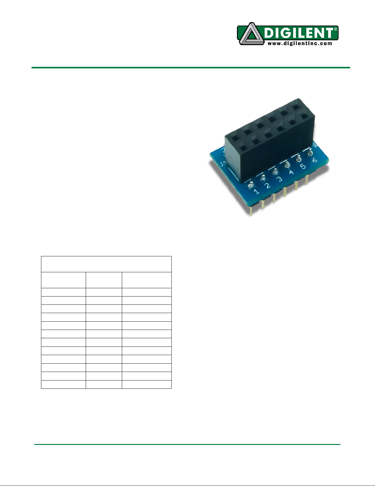
Overview
The PmodDIP is a 12-pin dual inline package
(DIP) module with one 2x6-pin Digilent
Pmod™ header. The PmodDIP connects to a
solderless breadboard.
Features include:
2x6 Pmod header
Functional Description
The PmodDIP adds Pmod support to a project
by routing signals from the two 6-pin DIP
interfaces to one 2x6-pin Pmod header.
Below is a pin out table for the PmodDIP. The
schematic is available for download on the
PmodDIP’s product page at digilentinc.com.
Interface Connector Signal Description
Doc: 502-261 page 1 of 1
Copyright Digilent, Inc. All rights reserved. Other product and company names mentioned may be trademarks of their respective owners.
 Loading...