

Page 1
P
mo
d
CDC1
™
Capacitance-to-Digital Converter
Reference Manual
Revision: October 4, 2012
Overview
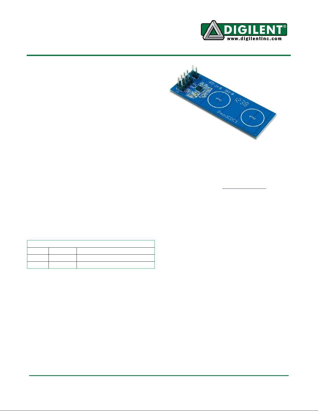
The PmodCDC1 demonstrates capacitance-todigital proximity sensing through two “buttons.”
Digilent engineers designed and built this
Pmod around the Analog Devices AD7156
Capacitance – to – Digital Converter.
Features include:
Functional Description
The PmodCDC1 has two capacitive buttons for
user input and two output pins on header J2
that signal when they reach a proximity
threshold. (See Table 1) The PmodCDC1
measures this threshold in capacitance, the
users can program the threshold, and it can be
either positive or negative. A logic high output
on header J2 will indicate which channel has
reached its threshold.
Connector J2 – AD7156 Output Pins
Pin Signal Description
1 OUT1 Threshold detected on CIN1
2 OUT2 Threshold detected on CIN2
Table1. Interface Connector Signal Description
Capacitance to Digital Conversion
The PmodCDC1 uses the AD7156 to measure
the capacitances of the two channels
separately by exciting the capacitance and
sampling the response. It stores data as a 16bit word that you can read by accessing the
correct data registers via I
The PmodCDC1 averages the capacitance of
each channel, which allows users to configure
2
I
C™ communication interface
two capacitance input channels
adaptive proximity threshold
2
C in the AD7156.
1300 Henley Court | Pullman, WA 99163
(509) 334 6306 Voice and Fax
the PmodCDC1 to adapt its threshold level.
The adaptive threshold is a programmable
feature of the AD7156.
For more detailed information on controlling
the AD7156, please see the device’s data
sheet, available from www.analog.com.
I2C Interface
The Analog Devices AD7156 acts as a slave
device using I
following instructions provide procedures for
reading and writing to the device.
The host device is the master when reading
from the PmodCDC1. If the host device
acknowledges the receipt of data, then the
AD7156 will auto increment the address
pointer and send the next byte of data in its
memory. The host device must assert a No
Acknowledge to the PmodCDC1 to cease
receiving data.
When reading a conversion value, assert an
Acknowledge between the first and second
byte in order to receive the bytes back to back.
Receiving them back to back will ensure that
data is not skipped between conversions.
Writing to the device is similar to reading from
it. After sending the first data byte, the address
pointer in the AD7156 will auto increment. If
the master sends another byte, then the
2
C communication protocol. The
Doc: 502-247 page 1 of 2
Copyright Digilent, Inc. All rights reserved. Other product and company names mentioned may be trademarks of their respective owners.
Page 2

PmodCDC1 Reference Manual
AD7156 will store that byte in this location and
it will increment the address pointer again. This
process will continue until the host device
asserts a Stop condition.
The PmodCDC1 has an 8-pin connector that
allows for communication via I
interface standard uses two signal lines. These
2
are I
C Data and I2C Clock. These signals map
2
C. The I2C
to the serial data (SDA) and serial clock (SCL)
respectively on the AD7156. (See Table 2)
Connector J1 – I2C Communications
Pin Signal Description
1, 2 SCL I2C Clock
3, 4 SDA I2C Data
5, 6 GND Power Supply Ground
7, 8 VCC Power Supply (3.3V/5V)
Table 2. Interface Connector Signal Description
Power Supply
You must keep any external voltage you apply
to VCC between 1.8V and 3.6V to avoid
damaging the PmodCDC1.
Standard Pmod headers on Digilent boards
provide both 3.3 V and 5.0 V power supplies
for Pmods. Make sure that the jumper next to
the Pmod header shorts to the 3V3 supply.
Register Addresses
The AD5933 data sheet has a complete table
of register addresses and is available at
www.analog.com.
www.digilentinc.com page 2 of 2
Copyright Digilent, Inc.
 Loading...