

Page 1
Digilent PmodDPOT™ Digital
Potentiometer Reference Manual
Revision: September 07, 2012
1300 Henley Court | Pullman, WA 99163
(509) 334 6306 Voice and Fax
Connector J1 – SPI Communications
Pin
Signal
Description
1
CS
Chip Select
2
SDI
Serial Data In
3
N/A
Not Connected
4
SCLK
Serial Clock
5
GND
Power Supply Ground
6
VCC
Power Supply (3.3V/5V)
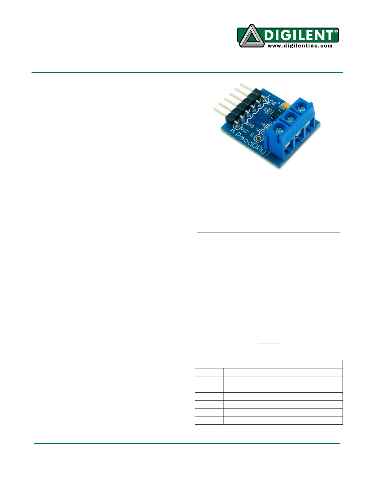
Overview
The PmodDPOT allows a Pmod™ compatible
host board to control a digital potentiometer.
Digilent engineers designed this Pmod around
the Analog Devices AD5160 Digital
Potentiometer.
Functional Description
For a detailed description of the Analog
Devices AD5160 please refer to the device
data sheet available at analog.com.
Users can access the PmodDPOT’s
programmed resistance through two methods.
The primary means of access is via a three
point screw terminal available on every
PmodDPOT. Users may, at their discretion,
load a 3-pin MTE cable header as an alternate
method of access.
The three terminal contacts are W (the wiper),
A, and B. The wiper contact resistance is 60 Ω.
Current flow between the wiper terminal and
either terminal A or B must be limited to a
pulsed ±20mA or a continuous 4.7mA. Do not
apply voltage to any of the terminal contacts
(A, W, or B) that exceeds the voltage rail
powering the Pmod. Given these current flow
limitations users must never apply a voltage to
the terminal contacts if a host board is not
powering the Pmod.
SPI Interface
The PmodDPOT communicates through a 3wire Serial Peripheral Interface (SPI) to
configure the Analog Devices AD5160. Note:
The Analog Devices AD5160 is write-only.
Table one describes the Pmod board header
pin functions. These are the control signals as
named on the AD5160.
Features include:
3-wire SPI™ communication interface
10 kOhm nominal resistance with minimal
achievable resistance ≈ 60 Ω
256 possible resistance settings
To establish a communication interface
connect the CS pin to the SS signal and the
SDI to the SDO signal on the host board.
Users can configure the AD5160 by sending
an 8-bit word to the device via SPI. Users can
access maximum resistance between terminal
A and W by sending 0xFF. Users may access
the maximum resistance between terminal B
and W by sending 0x00.
Table 1
Interface Connector Signal Description
Doc: 502-239 page 1 of 1
Copyright Digilent, Inc. All rights reserved. Other product and company names mentioned may be trademarks of their respective owners.
 Loading...