

Page 1
PPmmooddOOLLEEDD2
2
™
™
RReeffeerreennccee MMaannuuaal
l
Revision: September 18, 2012
Note: This document applies to REV B of the board.
1300 Henley Court | Pullman, WA 99163 (509)
334 6306 Voice and Fax
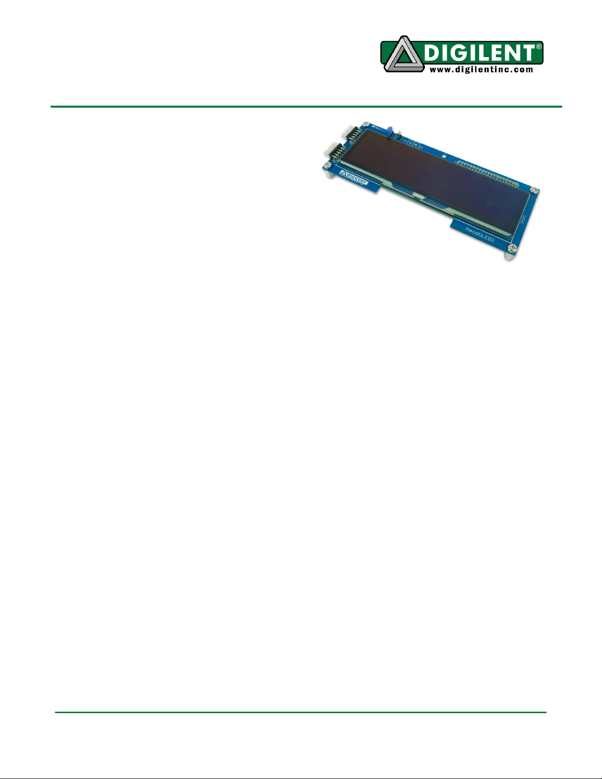
Overview
The PmodOLED2 features a parallel
controlled, 4-bit gray scale OLED display,
perfect for embedded applications requiring
complex visual output.
Features include:
a 256x64 pixel WiseChip/Univision UG-
5664ASGGF01 OLED graphic display
panel
5 3/8” x 1 3/8” display area
8080 Parallel interface
clock speeds of up to 10MHz
internal display buffer
Functional Description
The PmodOLED2 uses a standard 12-pin
connector to display output on a 256x64 pixel
organic LED (OLED) panel. The graphic
display panel uses the Solomon Systech
SSD1322 display controller.
A parallel interface is used to configure the
display, as well as to send the bitmap data to
the device.
The PmodOLED2 displays the last image
drawn on the screen until it is powered down or
a new image is drawn to the display.
Refreshing and updating is handled internally.
Power Supply
The PmodOLED2 has two field-effect
transistors (FETs) that control the display’s two
power supplies. The VCI/VDDIO control
toggles the power to the logic of the display,
and the I/O pins, respectively. The VCC control
toggles the power to the OLED display itself.
These two pins have pull-up resistors that turn
off their respective power supplies when
they’re not being driven. These pins are
configured as outputs and driven high to turn
on the power supply.
The UG-5664 display requires a 15V supply.
Header J5 can be used to connect a 15V
supply directly to the 15V supply line. To use
this option, jumper JP1 must be coving “EXT”.
Alternatively, the PmodOLED2 is equipped
with a step-up DC-DC converter, and
therefore, the 15V supply can be generated
from the supply voltage coming from the
development board’s Pmod header. That
supply voltage should be set so that it is
drawing from the 5V rail. There should be a
jumper next to the Pmod header for selecting
between the 3.3V and the 5V supply rail.
The PmodOLED2 has a particular poweron/power-off sequence that must be followed
to prolong the life of the display.
Power-on sequence:
1. Apply power to VCI.
2. Wait 300ms.
3. Send Display Off command.
4. Initialize display to desired operating mode.
5. Clear screen.
6. Apply power to VCC.
7. Delay 100ms.
8. Send Display On command.
Doc: 502-225 page 1 of 3
Copyright Digilent, Inc. All rights reserved. Other product and company names mentioned may be trademarks of their respective owners.
Page 2
PmodOLED2 Reference Manual
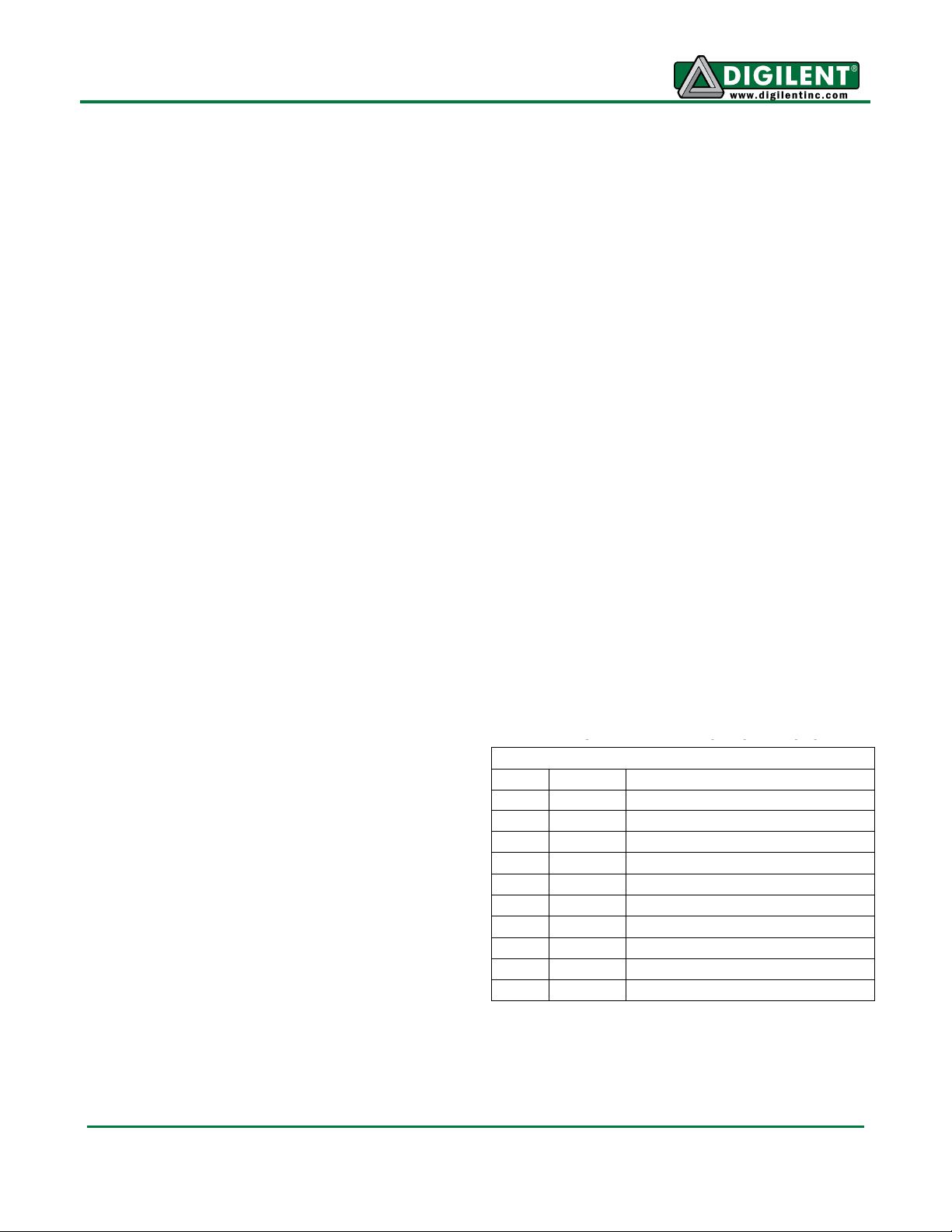
Connector J1
Pin
Signal
Description
1
D0
Parallel data bit 0
2
D1
Parallel data bit 1
3
D2
Parallel data bit 2
4
D3
Parallel data bit 3
7
D4
Parallel data bit 4
8
D5
Parallel data bit 5
9
D6
Parallel data bit 6
10
D7
Parallel data bit 7
5, 11
GND
Power Supply Ground
6, 12
VCC
Power Supply
Interface Connector Signal Description
Power-off sequence:
1. Send Display Off command.
2. Power off VCC.
3. Delay 100ms.
4. Power off VDD.
There are some considerations while operating
the PmodOLED2 while powering the board in
one of the two aforementioned ways.
If the PmodOLED2 is being powered from an
external source (i.e., JP1 is set to EXT), do not
remove, and then reconnect, power to the
PmodOLED2 while the development board is
still powered. The development board will not
know that the PmodOLED2 has been reset,
and therefore, the correct power-on sequence
will not be executed and the PmodOLED2 may
be damaged.
Gray Scale
The display on the PmodOLED2 is a 4-bit
grayscale display. This means that there are
16 levels of pixel brightness.
The grayscale level data (GS Level) for a pixel
is fetched from one half of a byte (a nibble)
stored in the on board Graphic Display Data
RAM (GDDRAM). The value will range from 015 (0x0 – 0xF).
The value stored in GDDRAM is then decoded
as a pulse width for the pixel’s driving current.
The pulse width values are stored in the Gray
Scale Table, which is defined upon initialization
of the device. This table will hold 16 values
ranging from 0-180. Gray Scale level 0 (pixel
off) is always set to 0, and cannot be changed.
Gray Scale levels 1-15 can have any value
between 0 and 180.
Interface
The display has a D/C pin (display or
command select) that determines whether
bytes sent to the display are interpreted as
commands or as display data. The D/C pin is
set high for display buffer access and low for
command access.
The RES pin is used to reset the SSD1322
display controller. The RES pin is driven low
for reset and driven high for normal operation.
The low-going reset pulse must be a minimum
of 3us (microseconds) in duration for the
display controller to reset correctly.
The UG5664 display has been designed as a
parallel device. The maximum parallel clock
frequency is 3.3MHz. The CS (Chip Select) pin
has to be held low for the display to receive
data over the parallel interface.
Digilent has libraries for the PmodOLED2 that
provide functions for initializing the display and
rendering simple text and graphics onto the
display. These libraries can be used as-is or as
a starting point for a more sophisticated
graphics library. They are available, with
documentation, on the PmodOLED2 product
page at www.digilentinc.com.
The OLED2 display uses a compatible
command set from the SSD1322 device. For
more information, see the SSD1306 datasheet
available at www.solomon-systech.com.
www.digilentinc.com page 2 of 3
Copyright Digilent, Inc. All rights reserved. Other product and company names mentioned may be trademarks of their respective owners.
Page 3

PmodOLED2 Reference Manual
Connector J2
Pin
Signal
Description
1
VCI/VD
DIO
V
CI
and V
DDIO
Voltage Control
2
RES
Power Reset
3
None
Unused Pin
4
VCC
V
BAT
Battery Voltage Control
7
D/C
Data/Command Control
8
E/RD
Read Data Enable
9
R/W
Write Date Enable
10
VDDC
VDD Logic Voltage Control
5, 11
GND
Power Supply Ground
6, 12
VCC
Power Supply
www.digilentinc.com page 3 of 3
Copyright Digilent, Inc. All rights reserved. Other product and company names mentioned may be trademarks of their respective owners.
 Loading...