

Page 1
PPmmooddBBTT22™
RReeffeerreennccee MMaannuuaal
Jumper
Description
Table 1: Set Jumper Description
Revision: August 17, 2011
Note: This document applies to REV A of the board.
™
l
Overview
The PmodBT2 is a powerful peripheral module
employing the Roving Networks® RN-42 to
create a fully integrated Bluetooth interface.
Features include:
• Bluetooth 2.1/2.0/1.2/1.1 Compatible
• Simple UART Interface
• A wide range of modes including: Slave
Mode, Master Mode, Trigger Master
Mode, Auto-connect Master Mode,
Auto-connect DTR Mode, and Autoconnect ANY Mode.
• Small form factor: 1.5” x 0.8”
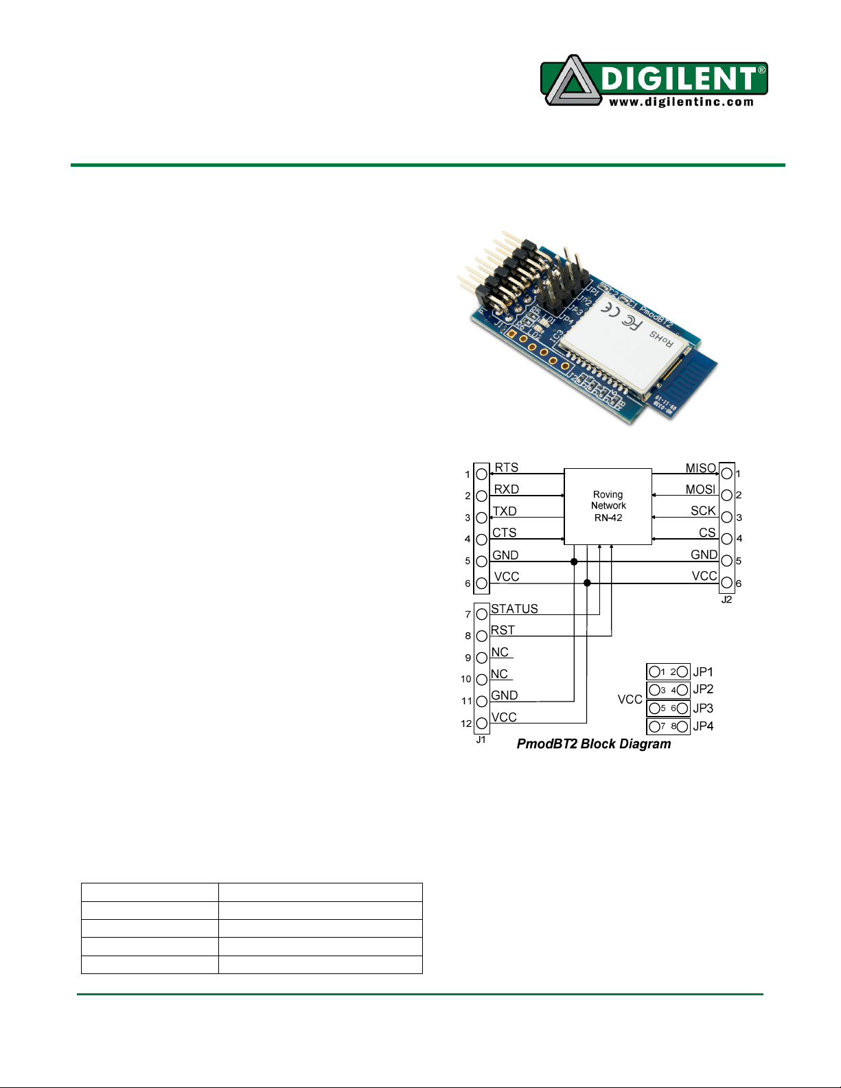
Functional Description
The PmodBT2 uses a standard 12-pin
connection and communicates via UART.
There is a secondary SPI header on the board
for updating the RN-42 firmware if needed.
Jumper Settings
The PmodBT2 has several modes available to
the user via jumper settings. JP1 through JP4
provide various modes of operation as
indicated in Table 1 below. Each jumper is
active when shorted. JP1 restores the device
to factor default settings after three transitions
of the jumper setting (short-to-open or open-toshort). After the third transition, the device
returns to factor default except for the
Bluetooth name. The other three jumpers, JP2JP4, only sample in the first 500 ms of
JP1 (PIO4) Factory Default
JP2 (PIO3) Auto Discovery/Pairing
JP3 (PIO6) Auto Connect
JP4 (PIO7) Baud Rate Setting (9600)
1300 NE Henley Court, Suite 3
Pullman, WA 99163
(509) 334 6306 Voice | (509) 334 6300 Fax
operation to allow the pins that they tie to on
the RN-42 module to serve a separate purpose
later in the modules operation. JP2 enables
pairing with a special device class defined by
the user in software. This may be used so that
the PmodBT2 operates as a substitute for an
RS232 cable. JP3 enables auto connect to a
stored address defined by the user. Finally,
JP4 chooses whether to operate at the stored
baud rate (115.2kbps default) or a baud rate of
9600 regardless of the software selected rate
when shorted. For more detailed information
Doc: 502-214 page 1 of 2
Copyright Digilent, Inc. All rights reserved. Other product and company names mentioned may be trademarks of their respective owners.
Page 2

PmodBT2™ Reference Manual
Connector J1
– UART
Communica
tions
Pin Signal
Description
Connector J2
– SPI Connector
on jumper settings and functionality, refer to
the RN-42 user manual.
UART Interface
By default, the UART interface uses a baud
rate of 115.2 kbps, 8 data bits, no parity, and a
single stop bit. The startup baud rate may be
customized to predefined rates or set to a
specific user customized baud rate. Predefined
baud rates range from 1200 to 921k.
The reset pin (RST) on J1 is active low. If the
RST pin is toggled, the device will undergo a
hard reset. This hard reset performs similarly
to a power cycling of the device. The second
interface besides the standard UART signals is
the STATUS pin also on J1The STATUS pin
directly reflects the connection status of the
device. STATUS is driven high by the device
when connected and is driven low otherwise.
For more information on the devices UART
interface and RST and STATUS pins refer to
the RN-42 user manual on the Roving
Networks website.
Command Mode
In order to enter the command mode, the
PmodBT2 must receive “$$$” to which it will
respond “CMD”. When in command mode, the
module will respond to a large number of
commands allowing the user to customizing
the module for specific applications. In order
to exit command mode, send “---<cr>” (three
minus signs in a row and where <cr> stands
for the carriage return character) to which the
device will respond “END”. Remote
configuration, or configuration over a Bluetooth
connection, is possible through the command
mode but has several restrictions. The
configure time, which defaults to 60 sec,
defines the time window in which the
PmodBT2 may be configured remotely.
Outside of this time, the PmodBT2 will not
respond to any remote commands. It is
important to note that any of the “set”
commands available for the PmodBT2 must be
followed by a power cycle to take effect in any
design.
1 RTS Ready to Send
2 RX Receive
3 TX Transmit
4 CTS Clear to Send
5 GND Power Supply
Ground
6 VCC Power Supply
(3.3V)
7 STATUS Connection
Status
8 ~RST Reset
9 NC Not Connected
10 NC Not Connected
11 GND Power Supply
Ground
12 VCC Power Supply
(3.3V)
(Firmware Update Only)
1 MISO Master in/
Slave out
2 MOSI Master out/
Slave in
3 SCK Serial Clock
4 ~CS Chip Select
5 VCC Power Supply
(3.3V)
6 GND Power Supply
Ground
Table 2: Connector Descriptions
The various modes of operation are accessed
by using the “SM,<5,4,3,2,1,0>” command
while in command mode. The PmodBT2 can
be put into one of six available modes of
operation. The modes in order, 0 to 5, are:
slave, master, trigger master, auto-connect,
auto-connect DTR, and auto-connect ANY. For
more detailed information on the different
modes of operation, refer to the RN-42 user
manual. For the full list of device commands,
how to use remote configuration, and more
detailed information on the different modes of
operation, see the RN-42 data.
www.digilentinc.com Copyright Digilent, Inc. page 2 of 2
 Loading...