

Page 1
PPmmooddNNIICC110000™™
RReeffeerreennccee MMaannuuaal
l
Revision: February 7, 2012
Note: This document applies to REV A of the board.
Overview
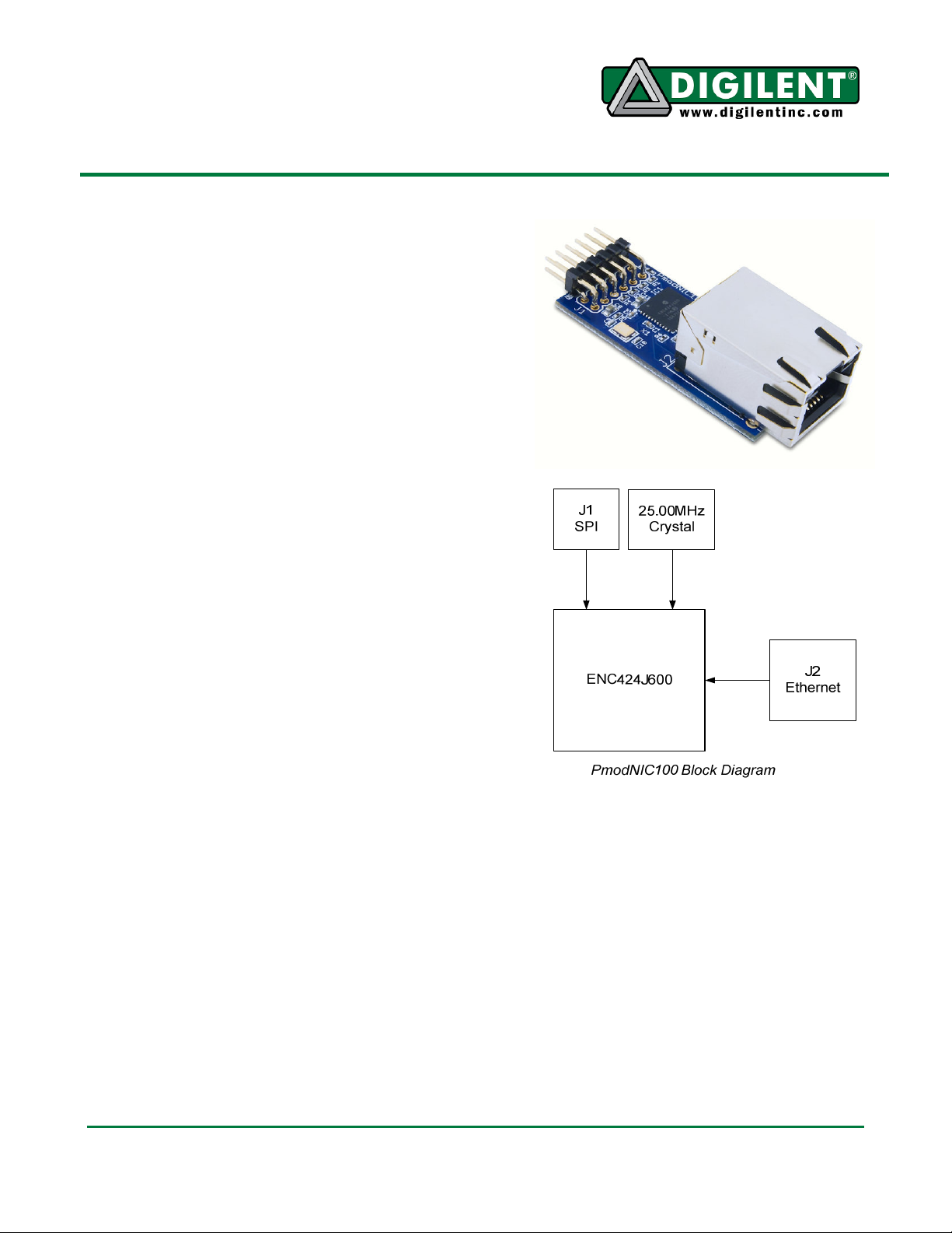
The PmodNIC100 is a peripheral module
designed to provide a complete Ethernet
interface. It features the Microchip®
ENC424J600 Stand-Alone Ethernet Controller.
The ENC424J600 provides integrated MAC
and PHY support, so the PmodNIC100 can
add Ethernet functionality to any Digilent
system board.
Features include:
• standard SPI interface
• 10/100 Mb/s data rates
• IEEE 802.3 compatible Ethernet
controller
• MAC support
• 10BASE-T support
• 100Base-TX support
Functional Description
The communications interface between the
PmodNIC100 and the host system board uses
an SPI bus. The PmodNIC100 communicates
in SPI mode 0 only, MSB first.
The INT/SPISEL pin is used by the
ENC424J600 to select use of the SPI interface
or a parallel interface. The INT/SPISEL pin
must be high when the ENC424J600 leaves
the power on reset state to enable the SPI
interface. This happens within 1µs to 10µs of
power on. Once completed, the INT/SPISEL
pin functions as an active low interrupt signal,
allowing a host to detect multiple interrupt
conditions on the PmodNIC100.
For more information about the hardware
connections, see the PmodNIC100 schematic
at www.digilentinc.com.
Doc: 502-208 page 1 of 2
Copyright Digilent, Inc. All rights reserved. Other product and company names mentioned may be trademarks of their respective owners.
-
The PmodNIC100 provides only the hardware
for a network interface. Protocol stack software
(such as TCP/IP) must be provided by the
user. The Microchip Applications Library,
available from the Microchip web site, provides
full network stack support for the ENC424J600
Ethernet controller.
For more information about the ENC424J600
Ethernet Controller, see the data sheet at
www.microchip.com.
1300 NE Henley Court, Suite 3
Pullman, WA 99163
(509) 334 6306 Voice | (509) 334 6300 Fax
Page 2

PmodXYZ Reference Manual
Connector J1
– SPI Communications
Pin Signal
Description
Connector J2
– Ethernet Interface
1 SS Slave Select
2 MOSI Master out/Slave in
Data
3 MISO Master in/Slave out
Data
4 SCK Serial Clock
5 GND Power Supply Ground
6 VCC Power Supply (3.3V)
7 INT/SPISEL SPI Enable/Interrupt
Signal
8 NC Not Connected
9 NC Not Connected
10 NC Not Connected
11 GND Power Supply Ground
12 VCC Power Supply (3.3V)
Interface Connector Signal Description
www.digilentinc.com page 2 of 2
Copyright Digilent, Inc. All rights reserved. Other product and company names mentioned may be trademarks of their respective owners.
 Loading...