

Page 1
PPmmooddKKYYPPDD™™ RReeffeerreennccee MMaannuuaal
Connector J1
– Column/Row Indicators
Pin Signal
Description
l
Revision: October 6, 2011
Note: This document applies to REV B of the board.
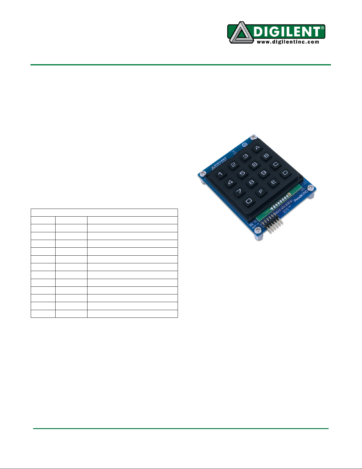
Overview
The PmodKYPD is an array of buttons used for
input.
Features include:
• 16 labelled keys (0-F)
• 12-pin header
Functional Description
The PmodKYPD uses a standard 12-pin Pmod
header that indicates which row and which
column has been pressed in the array of
buttons.
1300 NE Henley Court, Suite 3
Pullman, WA 99163
(509) 334 6306 Voice | (509) 334 6300 Fax
When a button in that column is pushed, the
corresponding row pin will read logic low.
All of the buttons can be read by walking a
logic 0 through each column pin (keeping the
other pins at logic high) and reading the row
pins. This will read the state of each button.
1 COL4 Column 4
2 COL3 Column 3
3 COL2 Column 2
4 COL1 Column 1
5 GND Power Supply Ground
6 VCC Power Supply (3.3V)
7 ROW4 Row 4
8 ROW3 Row 3
9 ROW2 Row 2
10 ROW1 Row 1
11 GND Power Supply Ground
12 VCC Power Supply (3.3V)
Device Usage
The PmodKYPD is set up as a matrix in which
each row of buttons from left to right are tied to
a row pin, and each column from top to bottom
is tied to a column pin. This gives the user four
row pins and four column pins to address the
button push.
To read a button’s state, the column pin in
which the button resides must be pulled low.
This enables all of the buttons in that column.
Doc: 502-195 page 1 of 1
Copyright Digilent, Inc. All rights reserved. Other product and company names mentioned may be trademarks of their respective owners.
 Loading...