

Page 1
PPmmooddSSFF22™™ MMeemmoorryy MMoodduullee
RReeffeerreennccee MMaannuuaal
l
Revision: February 8, 2012
Overview
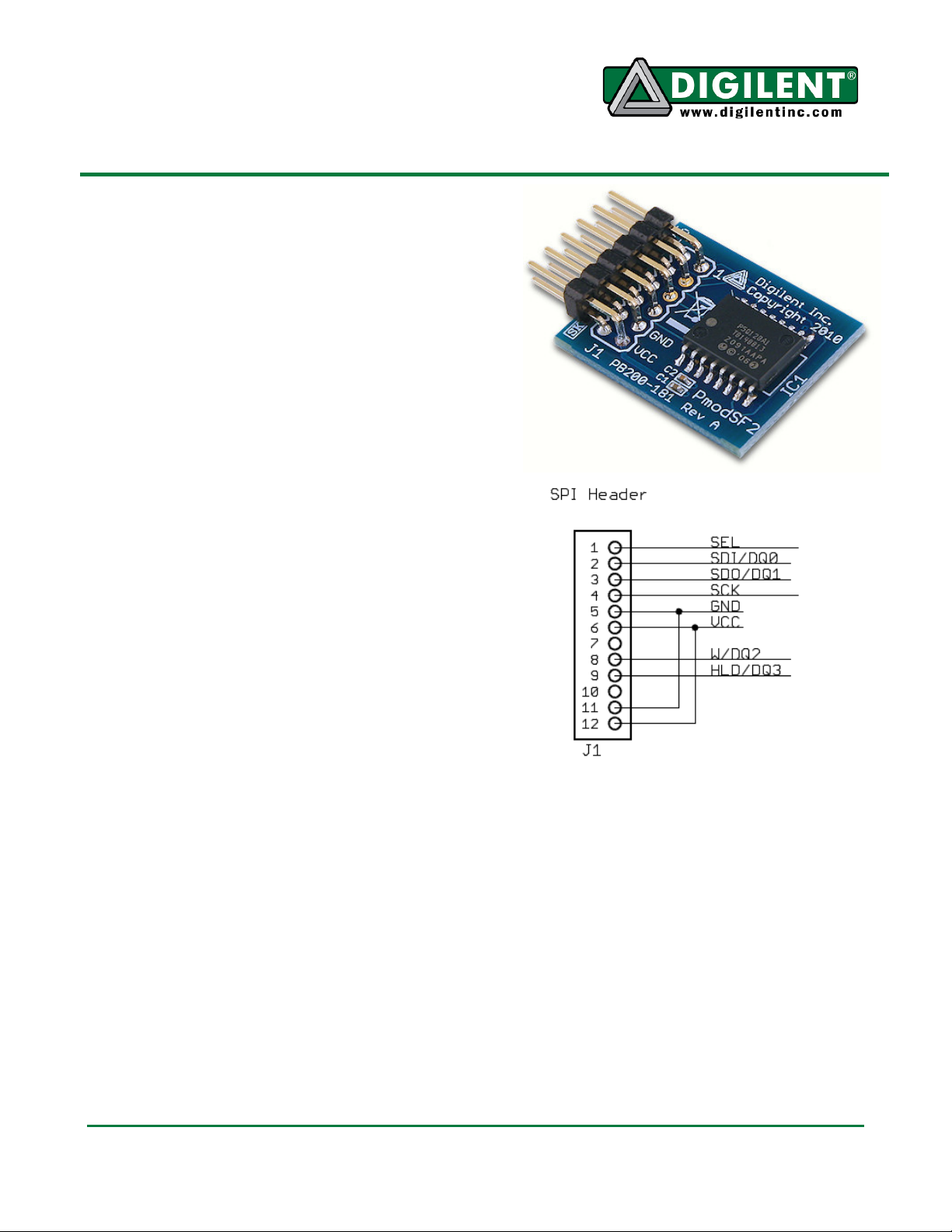
The PmodSF2 is a peripheral module that
provides 128Mbit (16Mbyte) of serial phase
change memory (PCM). This memory is
accessed through a legacy SPI (serial
peripheral interface) compatible serial
interface.
Features include:
• Micron P5Q PCM
128Mbit, Quad/Dual/Single Serial
Interface
• a 12-pin header Pmod interface
connector
• more than 1,000,000 write cycles
• high program performance with
low power
• small form factor (0.80” x 1.00”)
Functional Description
The PmodSF2 is used for easily-accessible
non-volatile memory storage for various
Digilent programmable-logic and embeddedcontrol system boards.
Note: The PmodSF2 is intended for direct
connection to boards with 12-pin Pmod
headers only. It is not intended for use with
Pmod cables.
The flash memory on the PmodSF2 is provided
by a Micron P5Q PCM integrated circuit. This
memory is organized as 128 sectors of
131,072 (128K) bytes each. Each sector is
organized as 1024 pages of 128 bytes each.
Flash memory must be erased before new
data can be written. The P5Q PCM supports
byte alterability, which allows direct overwrite
and eliminates erase operation. For legacy
compatibility, P5Q PCM supports emulated
erase operation. P5Q allows for a bulk erase or
1300 NE Henley Court, Suite 3
Pullman, WA 99163
(509) 334 6306 Voice | (509) 334 6300 Fax
Block Diagram
erase of individual sectors. After a sector has
been erased, individual bytes within the sector
can be written as well as complete pages. The
entire memory can be written as a single write
operation.
Flash memory will eventually wear out after
many erase/program cycles. The P5Q PCM
supports more than 1,000,000 erase/program
cycles per sector before the memory wears
out. Flash memory wear-out is usually not an
issue in routine operation but bugs in the
control software can cause many
erase/program cycles to happen quickly.
Doc: 502-181 page 1 of 2
Copyright Digilent, Inc. All rights reserved. Other product and company names mentioned may be trademarks of their respective owners.
Page 2
PmodSF2 Memory Module Reference Manual
Pin Signal
The legacy SPI interface standard uses four
signal lines. These are SS, slave select; MOSI,
master out slave in; MISO, master in slave out;
and SCK, serial clock. These signals map to
the following signals on the P5Q PCM part as
described in the Micron datasheet: SS
corresponds to the Chip Select signal (),
MOSI corresponds to Serial Data Input (D),
MISO corresponds to Serial Data Output (Q),
and SCK corresponds to the Serial Clock
signal (C). See the Micron datasheet for
descriptions of the Dual and Quad modes of
operation, as well as the use of the Write
Protect ( ) and Hold ( ) signals.
A system board interacts with the PmodSF2
module by sending commands over the SPI
interface. Depending on the command sent,
the system board sends memory data to, or
receives memory data from, the module.
The P5Q PCM provides commands to perform
sector erase, bulk erase, page program, and
write commands as well as other
miscellaneous commands.
Refer to the Micron P5Q PCM IC data sheet
for detailed information on the operation of this
integrated circuit.
The PmodSF2 requires a 2.7V- 3.6V supply
voltage. This power supply voltage (3.3V) is
available on all Digilent system boards and is
provided as part of the 12-wire Pmod interface
standard. Digilent system boards that provide
Pmod interface connectors allow jumper
selection of the power supply voltage being
provided to the Pmod. Ensure that the system
board is jumpered to provide 3.3V to the
module before applying power to the board.
For detailed information on the P5Q PCM, see
the Micron data sheet provided on the
PmodSF2 product page.
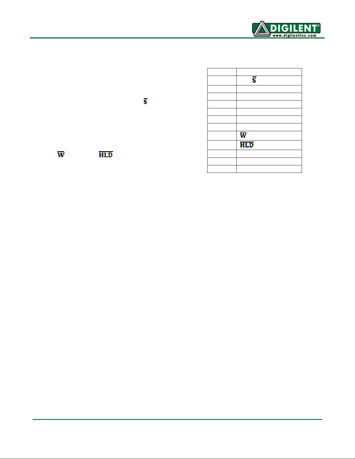
Connector J1 Signals
1
SS ( )
2 MOSI (D/DQ0)
3 MISO (Q/DQ1)
4 SCK (C)
5 GND
6 VCC
7 Not Used
8
9
/DQ2
/DQ3
10 Not Used
11 GND
12 VCC
www.digilentinc.com page 2 of 2
Copyright Digilent, Inc. All rights reserved. Other product and company names mentioned may be trademarks of their respective owners.
 Loading...