

Page 1
PPmmooddRR22RR™
Signals and Connector Pinouts
RReeffeerreennccee MMaannuuaal
Revision: February 6, 2009
Note: This document applies to REV B of the board.
™
l
Overview
The PmodR2R board provides digital-to-analog
conversion using a circuit that has been a
staple in engineering design for decades. The
board provides an easy way to gain insight and
experience with R2R circuits.
Features include:
• 8-bit digital to analog conversion at up
to 25MHz
• easy attachment of oscilloscopes to
illustrate the data conversion process
• rugged construction
Functional Description
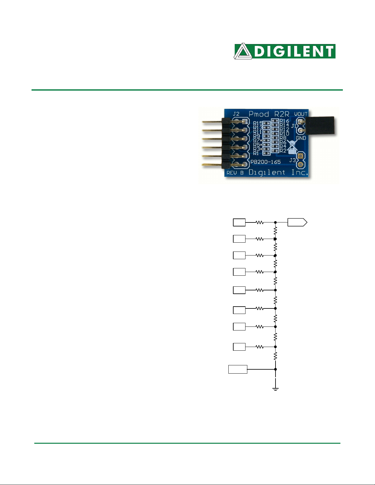
The PmodR2R board provides an R2R
resistor divider network that can convert an
8-bit digital input signal to an analog value.
The board uses 20K and 10K resistors, so
very little current is drawn from input source
pins. Separate GND and analog signal-out
connections are provided. The output
analog signal is also connected to a 2-pin
header at J1. J3 provides a 2-pin test point
for easy measurement of analog signals.
®
www. d i g i l e n t i n c . c om
215 E Main Suite D | Pullman, WA 99163
(509) 334 6306 Voice and Fax
J2 Pin
P10
P9
P8
P7
P4
P3
P2
P1
Signal
D7
D6
D5
D4
D3
D2
D1
D0
20K
20K
20K
20K
20K
20K
20K
20K
Output
10K
10K
10K
10K
10K
10K
10K
20K
Doc: 502-165 page 1 of 1
Copyright Digilent, Inc. All rights reserved. Other product and company names mentioned may be trademarks of their respective owners.
GND
 Loading...