

Page 1
DDiiggiilleenntt PPmmooddSSSSDD™™ PPeerriipphheerraall MMoodduullee
®
BBooaarrdd RReeffeerreennccee MMaannuuaall
Revision: March 6, 2007
Overview
The PmodSSD offers a single two-digit sevensegment display device (7sd) that can attach
directly to any Digilent system board. The 7sd
uses high-bright LEDs that can are easily
readable with less than 5mA of current, so they
can be driven directly from most system
boards.
Features include:
• two high bright seven-segment displays
• a 6-pin system connector
• small form factor (0.80” x 0.80”).
Functional Description
The two digits on the common cathode sevensegment LED display are each composed of
seven segments arranged in a “figure 8”
pattern, with an LED embedded in each
segment. Segment LEDs can be individually
illuminated, so any one of 128 patterns can be
displayed on a digit by illuminating certain LED
segments and leaving the others dark. Of
these 128 possible patterns, the ten
corresponding to the decimal digits are the
most useful.
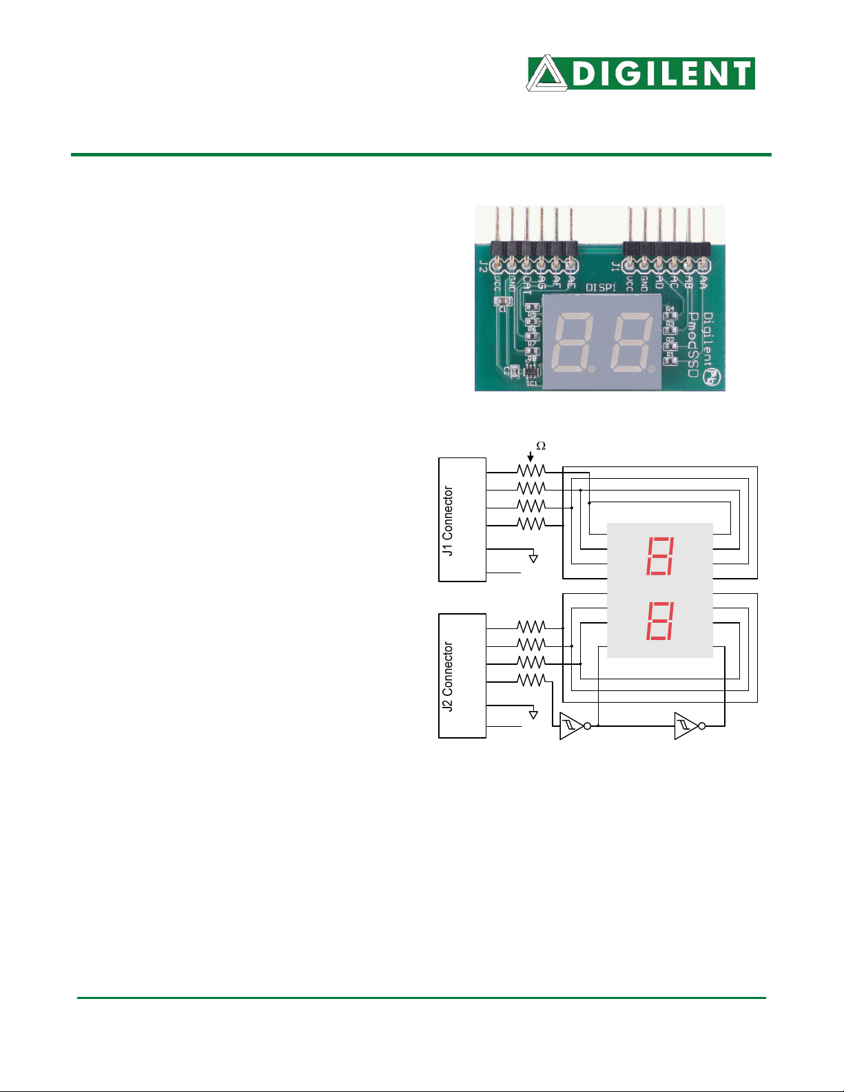
The cathodes of the seven LEDs forming each
digit are tied together into one “common
cathode” circuit node, but the LED anodes
remain separate. The common cathode signals
are available as two “digit enable” input signals
to the display. The anodes of similar segments
on both digits are connected into seven circuit
nodes that are available from the Pmod
connector pins (so, for example, the two “D”
anode signals from the two digits are
connected to the P4 pin on J1). These seven
anode signals are available as inputs to the 2digit display. This signal connection scheme
www. d i g i l e n t i n c . c om
215 E Main Suite D | Pullman, WA 99163
(509) 334 6306 Voice and Fax
560
AA
P1
AB
P2
AC
P3
AD
P4
GND
Vcc
AE
P1
AF
P2
AG
P3
C
P4
GND
GND
Vcc
Vcc
Seven-Segment Display Connection Diagram
creates a multiplexed display, where the anode
signals are common to both digits but they can
only illuminate the segments of the digit whose
corresponding cathode signal is asserted.
A scanning display controller circuit can be
used to show a two-digit number on the
display. This circuit drives the anode signals
and corresponding cathode patterns of each
AA1
AB1
AC1
AD1
AE1
AF1
AG1
C1
AA2
AB2
AC2
AD2
AE2
AF2
AG2
C2
Doc: 502-126 page 1 of 2
Copyright Digilent, Inc. All rights reserved. Other product and company names mentioned may be trademarks of their respective owners.
Page 2
PmodSSD Reference Manual Digilent, Inc.
digit in a repeating, continuous succession, at
an update rate that is faster than the human
eye can respond. Each digit is illuminated onehalf of the time, but because the eye cannot
perceive the darkening of a digit before it is
illuminated again, the digit appears
continuously illuminated. If the update or
“refresh” rate is slowed to a given point
(around 45 hertz), then most people will begin
to see the display flicker.
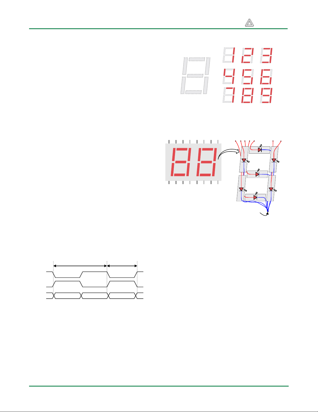
In order for each of the four digits to appear
bright and continuously illuminated, both digits
An un-illuminated seven-segment display, and nine
illumination patterns corresponding to decimal digits
should be driven once every 1 to 16ms (for a
refresh frequency of 1KHz to 60Hz). For
example, in a 60Hz refresh scheme, the entire
Individual anodes
display would be refreshed once every 16ms,
and each digit would be illuminated for ½ of the
refresh cycle, or 8ms. The controller must
assure that the correct anode pattern is
F
A
B
present when the corresponding cathode
signal is driven. To illustrate the process, if
Cat1 is asserted while AB and AC are
asserted, then a “1” will be displayed in digit
position 1. Then, if Cat2 is asserted while AA,
AB and AC are asserted, then a “7” will be
displayed in digit position 2. If Cat1 and AB,
AC are driven for 8ms, and then Cat2 and AA,
Two-digit Seven
Segment Display
E
Common cathode
G
D
C
AB, AC are driven for 8ms in an endless
succession, the display will show “17”. An
example timing diagram for a two-digit
controller is shown below.
Refresh period:
1ms to 16ms
Digit period:
Refresh / 2
Cat1
Cat2
Anodes
Digit 1Digit 0 Digit 0
www.digilentinc.com Copyright Digilent, Inc. Page 2
 Loading...