

Page 1
PPmmooddSSDD™
RReeffeerreennccee MMaannuuaal
Revision: December 18, 2009
Note: This document applies to REV B of the board.
™
l
Overview
The PmodSD Secure Digital memory card
module provides a convenient SD card slot for
use with Digilent system and microcontroller
boards.
Features include:
• a 2x6 pin header
• an SD card slot
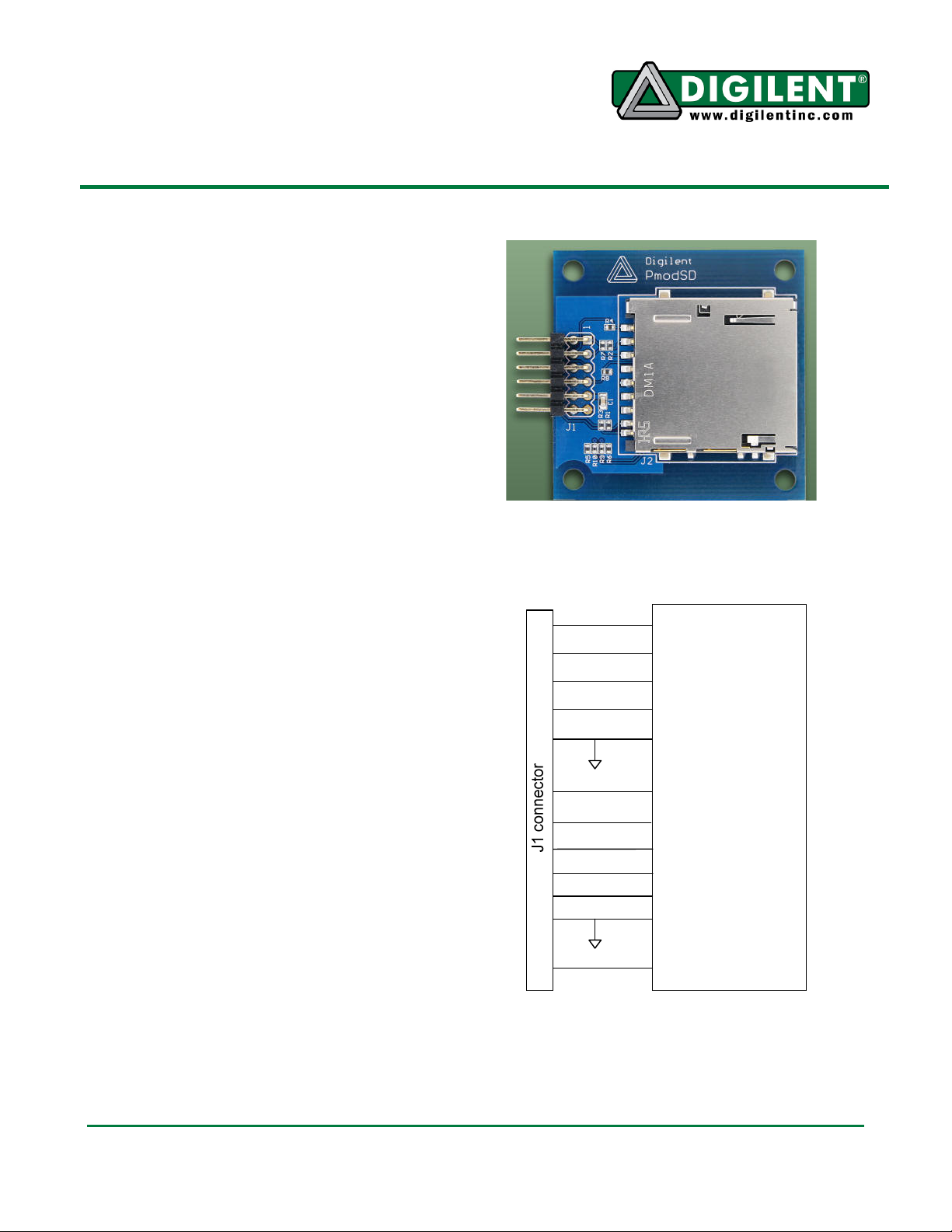
Functional Description
The PmodSD connects to all communication
and power signals from a standard SD card
and brings them out to the 2x6 pin header on
the board.
The pinout placement on the PmodSD is
designed to readily communicate with a
Digilent system board via SPI. The SPI
interface standard uses four signal lines: SS
(slave select), MOSI (master out slave in),
MISO (master in slave out), and SCK (serial
clock).
SD cards can also be driven in a native mode
that also uses the DAT1 and DAT2 signals as
well as the DAT0, DAT3, CMD, and CLK
signals.
The WP signal can be set by a switch on the
SD card to prevent the host from writing or
erasing data on the card. The CD signal can
be used by the host to indicate that a card is in
the SD slot and is detectable.
For more information on the necessary
commands to communicate with an SD card,
see the card’s data sheet.
215 E Main Suite D | Pullman, WA 99163
(509) 334 6306 Voice and Fax
1 SS CS/DAT3
2 MOSI DI/CMD
3 MISO DO/DAT0
4 SCK CLK
5 GND VSSI
6 VCC VDD
SD card slot
7 DAT1 DAT1
8 DAT2 DAT2
9 CD CD
10 WP WP
11 GND VSSI
12 VCC VDD
Doc: 502-123 page 1 of 1
Copyright Digilent, Inc. All rights reserved. Other product and company names mentioned may be trademarks of their respective owners.
 Loading...