

Page 1
PPmmooddEENNCC™™ RReeffeerreennccee MMaannuuaal
l
Revision: October 31, 2011
Note: This document applies to REV A of the board.
Overview
The PmodENC Rotary Encoder Module
features a rotary shaft encoder with integral
push-button that provides rotate-right, rotateleft, and button-press outputs. The module also
includes a sliding switch that provides an on/off
output.
Features include:
• a rotary push-button shaft encoder
• a slide switch with a series resistor
• a 6-pin header
• small form factor (1.5” x 0.75”).
Functional Description
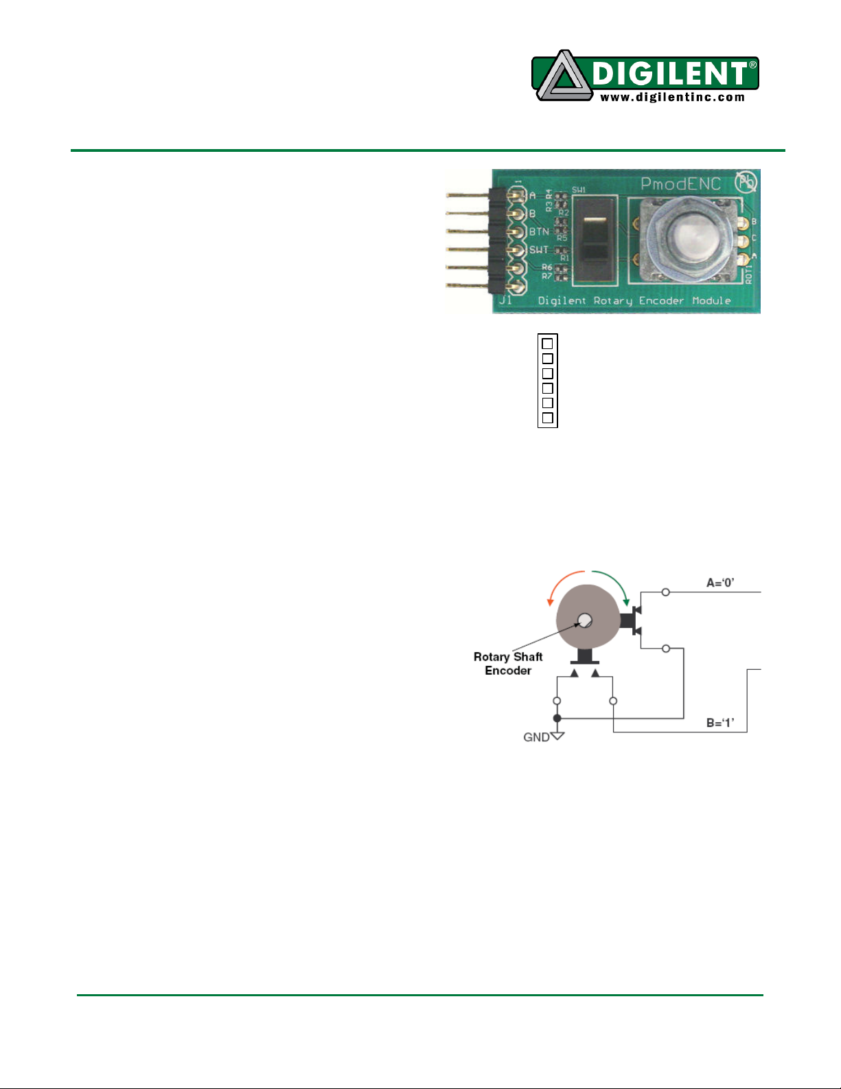
There are four outputs on the PmodENC
module, labeled A, B, BTN, and SWT. Outputs
A and B are the encoded outputs from the
rotary shaft encoder. In principle, the rotary
shaft encoder behaves like a cam connected to
a central shaft. Rotating the shaft operates two
push-button switches, as shown in Figure 2.
Depending on which way the shaft is rotated,
one of the switches closes before the other.
Likewise, as the rotation continues, one switch
opens before the other. When the shaft is
stationary (the detent position) both switches
are open (logic 1).
1300 NE Henley Court, Suite 3
Pullman, WA 99163
(509) 334 6306 Voice | (509) 334 6300 Fax
1 = A
2 = B
3 = BTN
4 = SWT
5 = GND
6 = VCC
Figure 1 PmodENC Pin Signals
Figure 2 Rotary Shaft Encoder Circuitry
Doc: 502-117 page 1 of 2
Copyright Digilent, Inc. All rights reserved. Other product and company names mentioned may be trademarks of their respective owners.
Page 2
PmodXYZ Reference Manual
Pressing the rotary push-button shaft encoder
will drive the output pin BTN to VCC voltage or
a logic level 1. Otherwise BTN is driven to
GND voltage or a logic level 0.
Placing the slide switch into the up position on
the PmodENC module will drive the output
SWT to VCC voltage or a logic level 1. Placing
the slide switch in the down position will drive
SWT to GND voltage or a logic level 0.
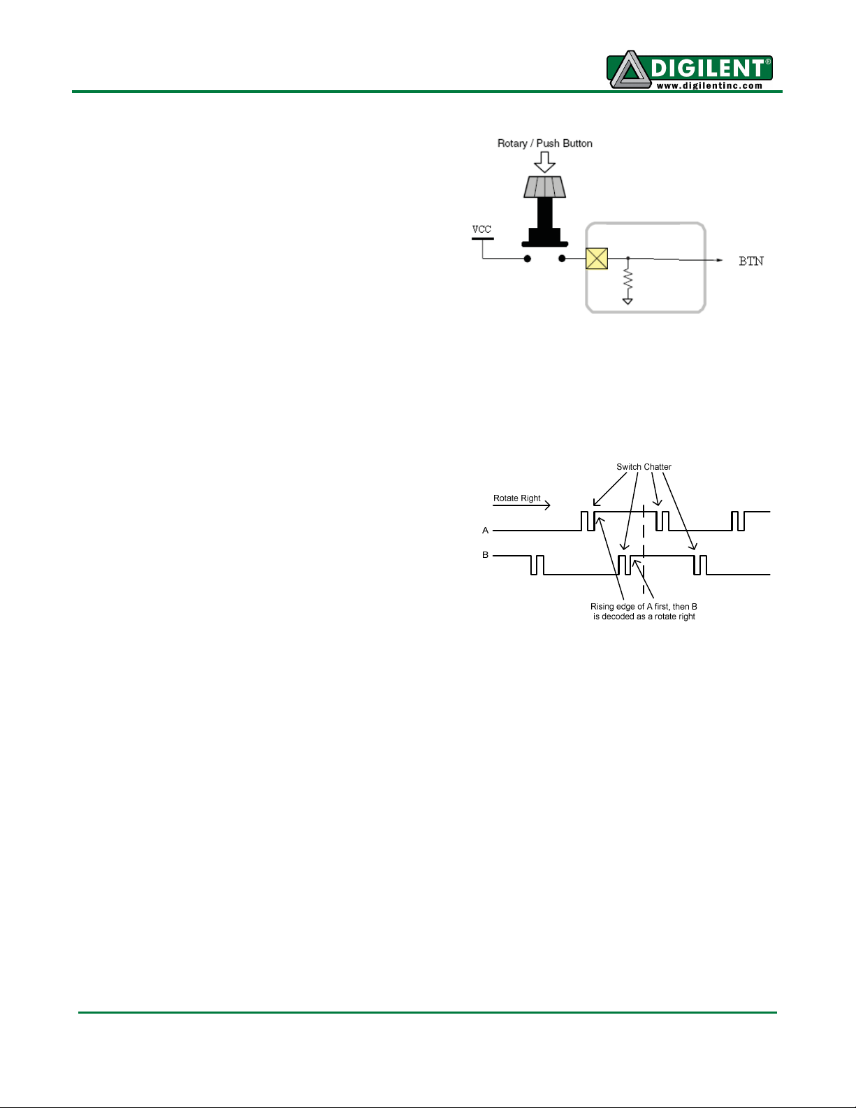
Decoding Rotations of the Rotary
Shaft
Figure 4 shows a timing diagram of a rotateright on the rotary push-button shaft of the
PmodENC module. Note the logic noise shown
with opening and closing of the switches. A
rotate-left of the rotary push-button shaft is
similar to Figure 4. The only difference is that
output B will drop to logic level 0 first, followed
by output A.
Figure 3 Push-Button Circuitry
Detent
Figure 4 Timing of Outputs A and B
www.digilentinc.com page 2 of 2
Copyright Digilent, Inc. All rights reserved. Other product and company names mentioned may be trademarks of their respective owners.
 Loading...