

Page 1
DDiiggiilleenntt PPmmooddHHBB55™
22AA HH--BBrriiddggee RReeffeerreennccee MMaannuuaall
™
®
Revision: February 28, 2012
Note: This document applies to REV D of the board.
Overview
The Digilent PmodHB5TM 2A H-Bridge Module
(the HB5) is an ideal solution for robotics and
other applications where logic signals are used
to drive small to medium-sized DC motors,
such as the Digilent motor-gearbox.
Features include:
• a 2A H-bridge circuit for voltages up to
12V
• a JST 6-pin connector for direct
connection of Digilent motor-gearboxes
• a 2-channel quadrature encoder with
Hall-effect sensors to detect motor
speed
• small form factor (0.8” x 1.30”)
Functional Description
The HB5 works with power supply voltages
from 2.5V to 5V, but is normally operated at
3.3V as this is the supply voltage on most
Digilent system boards.
The HB5 is designed to work with either
Digilent programmable logic system boards or
embedded control system boards. Most
Digilent system boards, such as the Nexys,
Basys, or Cerebot, have 6-pin connectors that
allow the HB5 to plug directly into the system
board or to connect via a Digilent 6-pin cable.
Some older Digilent boards may need a
Digilent Module Interface Board (MIB) and a 6pin cable to connect to the HB5. The MIB plugs
into the system board and the cable connects
the MIB to the HB5.
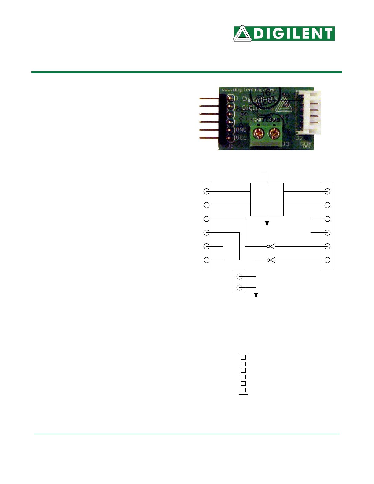
DIR
EN
SA
SB
GND
VCC
J1 J2
www. d i g i l e n t i n c . c om
215 E Main Suite D | Pullman, WA 99163
(509) 334 6306 Voice and Fax
VM
M+
H-BRIDGE
CIRCUIT
GND
VM
GND
J3
M-
VCC
GND
Motor power is provided via a two-pin terminal
block (J3) that can accommodate up to 18gauge wire. The HB5 circuits can handle motor
voltages up to 12V.
Direction
Enable
Sensor A
Sensor B
GND
Vcc (3.3 - 5v)
HB5 6-Pin Header, J1
Doc: 502-106 page 1 of 3
Copyright Digilent, Inc. All rights reserved. Other product and company names mentioned may be trademarks of their respective owners.
Page 2
PmodHB5 Reference Manual
The HB5 is controlled by a system board
connected to J1. The motor rotation direction is
determined by the logic level on the Direction
pin. Current will flow through the bridge when
the Enable pin is brought high. Motor speed is
controlled by pulse width modulating the
Enable pin. See below for a description of
pulse width modulation. The direction of the
motor should not be reversed while the Enable
pin is active. If the direction is reversed while
the bridge is enabled it is possible to create
brief short circuits across the bridge as one leg
will be turning on while the other leg is turning
off. This could damage the bridge transistors.
Two Schmitt trigger buffered inputs are
provided on connector J2 to facilitate bringing
motor speed feedback signals to the controlling
system board. The Digilent motor/gearboxes
have Hall-effect sensors arranged as a
quadrature encoder. These buffers have 5V
tolerant inputs when operated at 3.3V.
The quadrature encoder signals are a pair of
square waves whose frequency is proportional
to motor rotation speed and which are 90° out
of phase. Motor speed can be determined by
the frequency and motor rotation direction can
be determined by the phase relationship of the
two signals.
Pulse Width Modulation and Motor
Speed Control
In an analog circuit, motor speed is controlled
by varying the input voltage to a circuit. In a
digital circuit, however, only a logic high or
logic low signal can be applied to the motor.
Therefore, there are only two ways to control a
motor digitally: use a variable resistance circuit
to control the motor voltage, or, pulse the
power to the motor. Since variable resistance
circuitry is expensive, complicated, and wastes
much energy in the form of heat, the better
solution is pulse width modulation (PWM).
Digilent, Inc.
www.digilentinc.com
Pulse width modulation is a digital method of
transmitting an analog signal, and while it is
not a clean source of DC output voltage, PWM
suits motors relatively well.
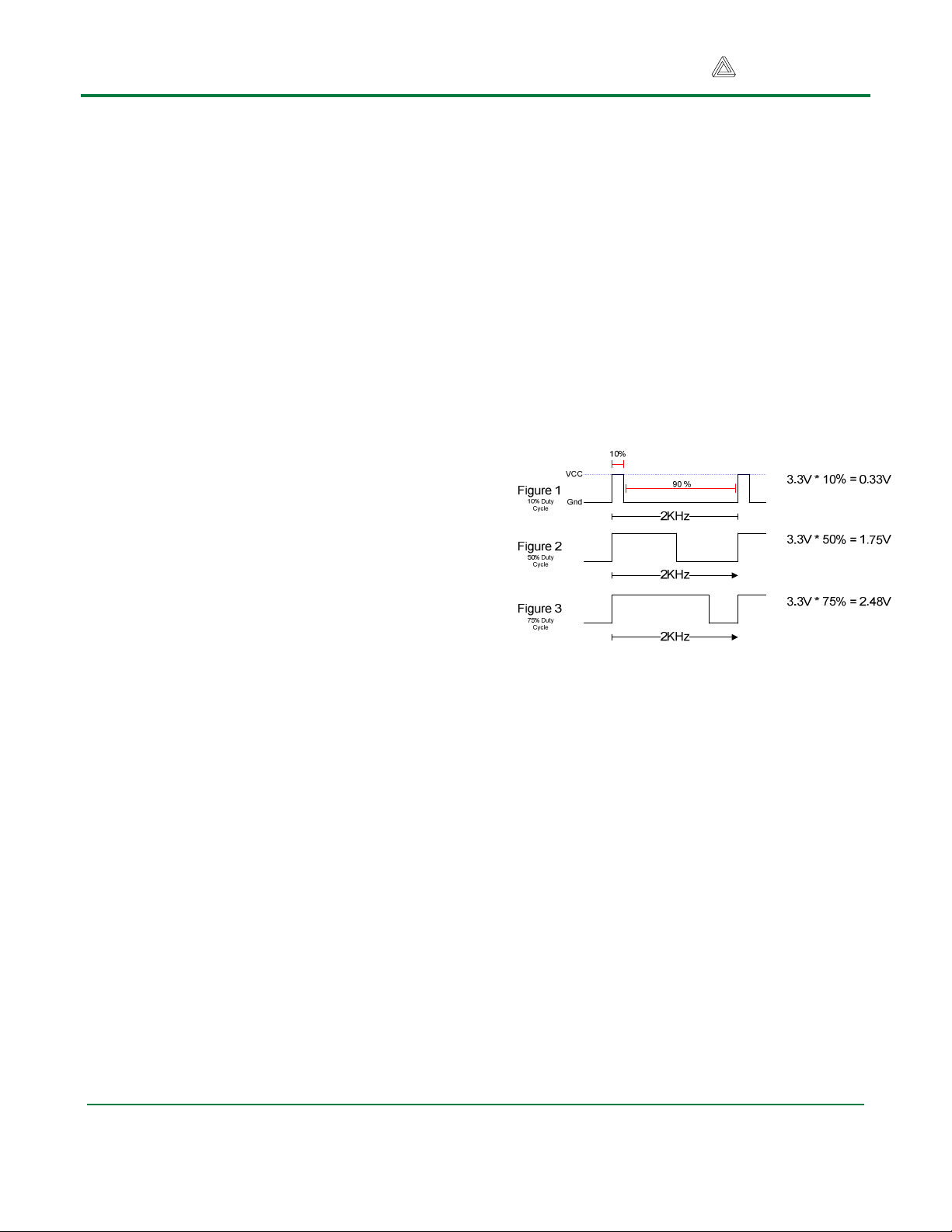
The figures below illustrate a PWM system
with an input frequency of 2KHz. The motor
speed is controlled by adjusting the time each
wave is at peak output power. Figure 1 shows
a 10% “duty cycle” where the signal is logic
high for only 1/10 of a wavelength. This 10%
positive peak is equal to 10% of the total 3.3V
input, or 0.33V (shown in Figure 2). Figures 2
and 3 show duty cycles of 50% and 75%,
respectively.
An H-bridge is a voltage amplification and
direction control circuit that is used to format
the signal to the appropriate motor voltage and
polarity to spin the motor.
While voltage is being applied, the motor is
driven by the changing magnetic forces. When
voltage is stopped, momentum causes the
motor to continue spinning a while. At a high
enough frequency, this process of powering
and coasting enables the motor to achieve a
smooth rotation that can easily be controlled
through digital logic.
PWM has two important effects on DC motors.
Inertial resistance is overcome more easily at
startup because short bursts of maximum
voltage achieve a greater degree of torque
than the equivalent DC voltage. Another effect
is a higher level of heat generation inside the
www.digilentinc.com page 2 of 3
Copyright Digilent, Inc. All rights reserved. Other product and company names mentioned may be trademarks of their respective owners.
Page 3

PmodHB5 Reference Manual
motor. If a pulsed motor is used for an
extended time, heat dissipation systems may
be needed to prevent damage to the motor.
Because of these effects, PWM is best used in
high-torque infrequent-use applications such
as airplane flap servos and robotics.
PWM circuits can also create radio frequency
interference (RFI) that can be minimized by
locating motors near the controller and by
using short wires. Line noise created by
continually powering up the motor may also
need to be filtered to prevent interference with
the rest of the circuits. Placing small ceramic
capacitors directly across the motor terminals
and between the motor terminals and the
motor case can be used to filter RFI emissions
from the motor.
For more information see www.digilentinc.com.
Digilent, Inc.
www.digilentinc.com
www.digilentinc.com page 3 of 3
Copyright Digilent, Inc. All rights reserved. Other product and company names mentioned may be trademarks of their respective owners.
 Loading...