

Page 1
DDiiggiilleenntt PPmmooddPPSS//22™™ MMoodduullee
®
BBooaarrdd RReeffeerreennccee MMaannuuaall
Revision: August 3, 2006
Overview
The Digilent PmodPS/2 module board allows a
Digilent system board to send and receive
signals from a PS/2-style keyboard or mouse.
The PS/2 is designed for use with either a
Digilent programmable logic system board or a
Digilent embedded control system board.
Features include:
• a 6-pin header for connection to a
system board
• PS/2 connector for a keyboard or
mouse
• power routing jumpers
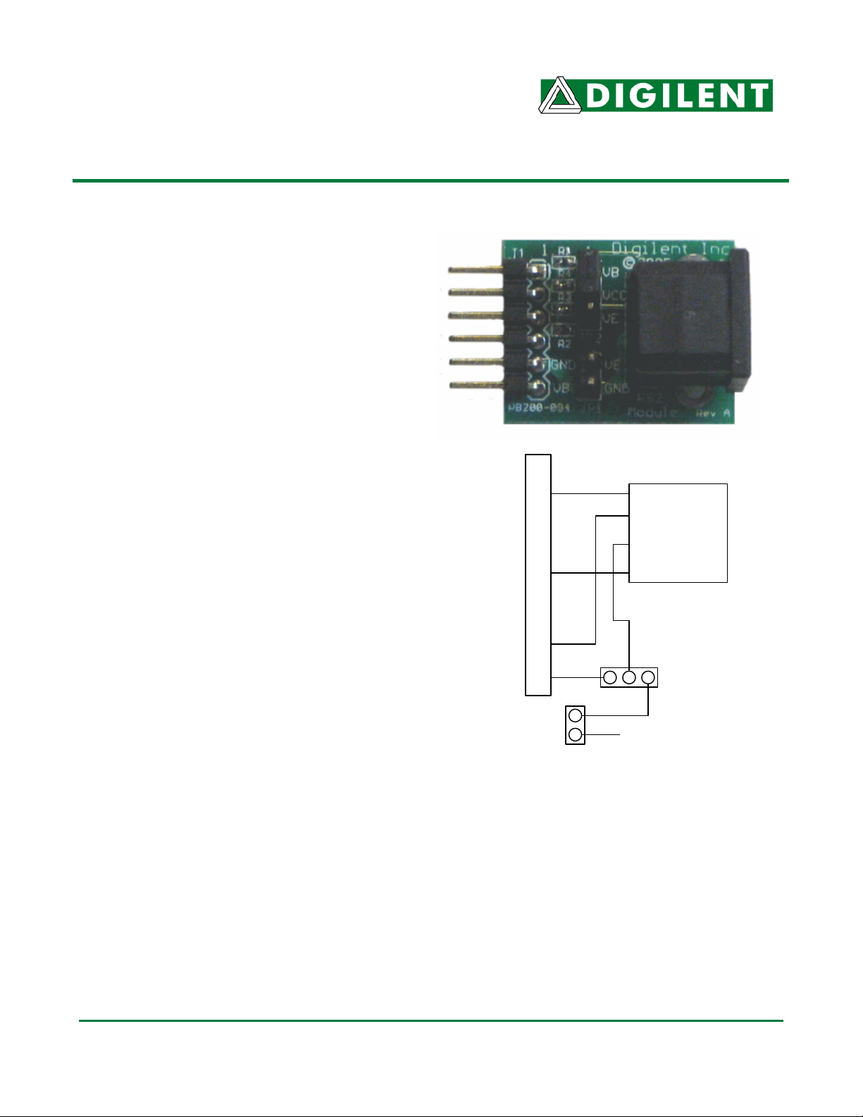
Functional Description
The PS/2 has a 6-pin header for easy
connection to a Digilent system board. Most of
Digilent’s programmable logic system boards
(like the Nexys™ or Basys™ boards) or
Digilent’s embedded control boards (like the
Cerebot™) have 6-pin connectors that allow
direct connection of the PS/2. To connect the
PS/2 to some older Digilent system boards, a
Digilent Modular Interface Board (MIB) and a
6-pin cable may be needed. The MIB plugs
into the system board, and the cable connects
the MIB to the PS/2.
Power to the keyboard or mouse can be
provided from the system board or an external
power supply. To power the keyboard or
mouse from the system board, set the shorting
block on jumper JP2 to the VB position. To
power the keyboard or mouse from an external
power supply, set the shorting bock on JP2 to
the VE position and attach the external power
supply to JP1. The external supply voltage is
attached to the VE pin of JP1 and the ground
JP1
for the external power supply is attached to the
GND pin of JP1.
NOTE: Some keyboards and mice can operate
with a 3.3V power supply but some require a 5V
power supply. Be careful to observe the correct
polarity when connecting an external power
supply to JP1 and do not use an external power
supply voltage greater than 5V.
www.digilentinc.com
215 E Main Suite D | Pullman, WA 99163
(509) 334 6306 Voice and Fax
P2
P4
J1 Connection
GND
VCC
VCC
GND
External Power
PmodPS/2 Circuit Diagram
Data
GND
VCC
CLK
PS/2
Connector
JP2
Doc: 502-094 page 1 of 4
Copyright Digilent, Inc. All rights reserved. Other product and company names mentioned may be trademarks of their respective owners.
Page 2
PS/2 Reference Manual Digilent, Inc.
Keyboard and Mouse Interface
Pin 1
Pin 2
1
2
6
PS/2
3
5
Pin 5Pin 6
Bottom-up
hole pattern
4
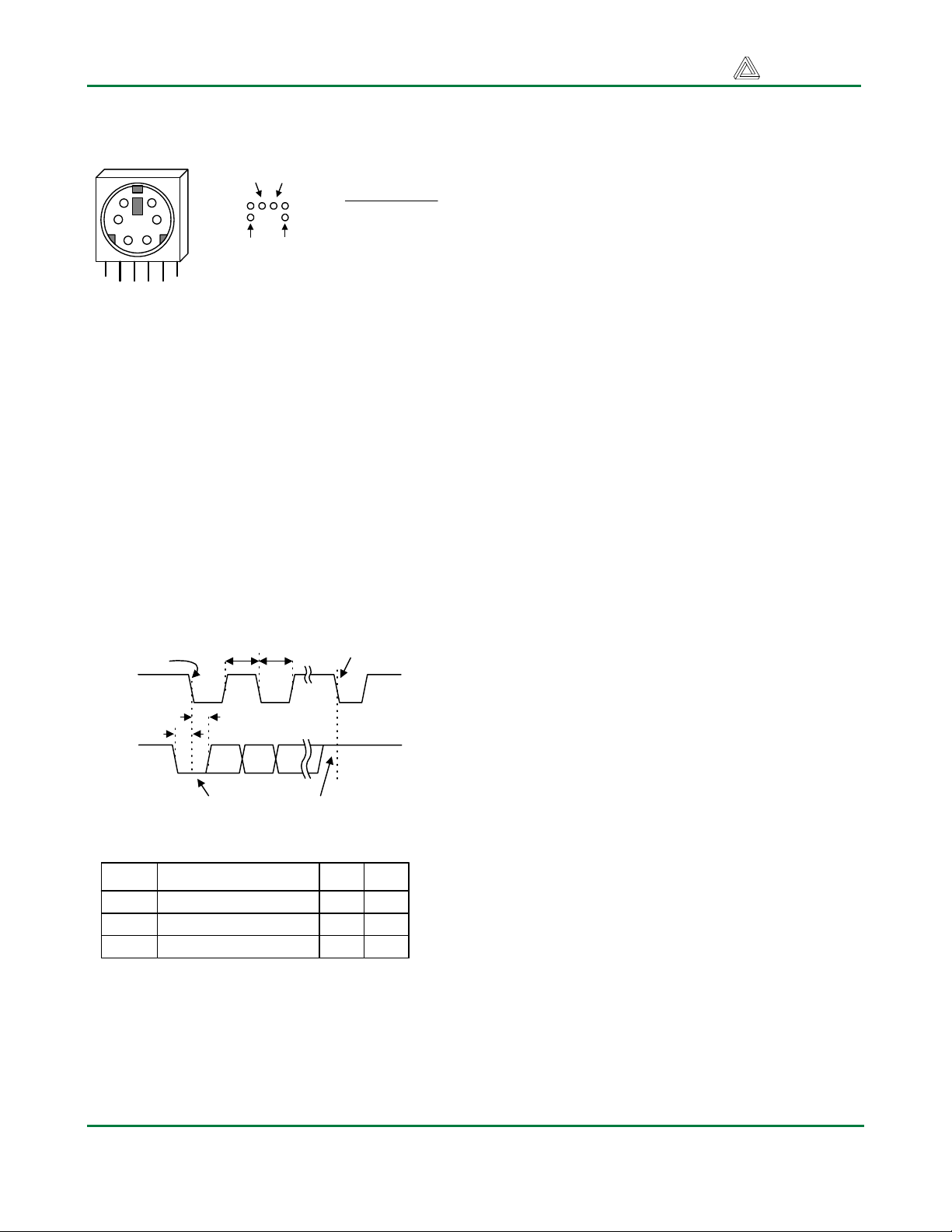
Connector
The keyboard and mouse both use identical
signal timings. Both use 11-bit words that
include a start, stop, and odd parity bit, but the
data packets are organized differently, and the
keyboard interface allows bi-directional data
transfers (so the host device can illuminate
state LEDs on the keyboard). Bus timings are
shown below. The clock and data signals are
only driven when data transfers occur, and
otherwise they are held in the “idle” state at
logic ‘1’. The timings define signal
requirements for mouse-to-host
communications and bi-directional keyboard
communications.
T
T
CK
Edge 0
CLK
DATA
T
SU
T
CK
HLD
'1' stop bit'0' start bit
Symbol Parameter Min Max
T
Clock time
CK
T
Data-to-clock setup time
SU
T
Clock-to-data hold time 5us 25us
HLD
Pin Definitions
Pin Function
1 Data
2 Reserved
3 GND
4 Vdd
5 Clock
6 Reserved
Edge 10
30us
5us
50us
25us
Keyboard
The keyboard uses open-collector drivers so that
either the keyboard or an attached host device
can drive the two-wire bus (if the host device will
not send data to the keyboard, then the host can
use simple input-only ports).
PS/2-style keyboards use scan codes to
communicate key-press data (nearly all
keyboards in use today are PS/2 style). Each
key has a single, unique scan code that is sent
whenever the corresponding key is pressed. If
the key is pressed and held, the scan code will
be sent repeatedly once every 100ms or so.
When a key is released, an “F0” key-up code is
sent, followed by the scan code of the released
key. If a key can be “shifted” to produce a new
character (like a capital letter), then a shift
character is sent in addition to the original scan
code, and the host device must determine which
character to use. Some keys, called extended
keys, send an “E0” ahead of the scan code (and
they may send more than one scan code). When
an extended key is released, an “E0 F0” key-up
code is sent, followed by the scan code. Scan
codes for most keys are shown in the keyboard
diagram below.
A host device can also send data to the
keyboard. Below is a short list of some oft-used
commands.
ED Set Num Lock, Caps Lock, and Scroll Lock
LEDs. After receiving an “ED”, the keyboard
returns an “FA”, then the host sends a byte to
set LED status. Bit 0 sets Scroll Lock, bit 1 sets
Num Lock; and Bit 2 sets Caps lock. Bits 3 to 7
are ignored.
EE Echo. Upon receiving an echo command, the
keyboard replies with “EE”.
F3 Set scan code repeat rate. The keyboard
acknowledges receipt of an “F3” by returning an
“FA”, after which the host sends a second byte
to set the repeat rate.
FE Resend. Upon receiving FE, the keyboard re-
sends the last scan code sent.
FF Reset. Resets the keyboard.
www.digilentinc.com page 2 of 4
Copyright Digilent, Inc. All rights reserved. Other product and company names mentioned may be trademarks of their respective owners.
Page 3

PS/2 Reference Manual Digilent, Inc.
ESC
76
` ~
0E
TAB
0D
Caps Lock
58
Shift
12
Ctrl
14
F105F206F304F4
0C
1 !162 @1E3 #264 $255 %
2E
Q
15W1DE24R2DT2C
A
1CS1BD23F2BG34
Z
1ZX22C21V2AB32
Alt
11
F503F60BF783F8
6 ^367 &3D8 *3E9 (460 )45- _4E= +55BackSpace
Y
35U3CI43O44P4D
Space
The keyboard sends data to the host only
when both the data and clock lines are high (or
idle). Since the host is the “bus master”, the
keyboard checks to see whether the host is
sending data before driving the bus. To
facilitate this, the clock line can be used as a
“clear to send” signal. If the host pulls the clock
line low, the keyboard will not send any data
until the clock is released.
The keyboard sends data to the host in 11-bit
words that contain a ‘0’ start bit, followed by 8bits of scan code (LSB first), followed by an
odd parity bit and terminated with a ‘1’ stop bit.
The keyboard generates 11 clock transitions
(at around 20 - 30KHz) when the data is sent,
and data is valid on the falling edge of the
clock.
Mouse
The mouse outputs a clock and data signal
when it is moved, otherwise these signals
remain at logic ‘1’. Each time the mouse is
moved, three 11-bit words are sent from the
mouse to the host device. Each of the 11-bit
words contains a ‘0’ start bit, followed by 8 bits
of data (LSB first), followed by an odd parity
bit, and terminated with a ‘1’ stop bit. Thus,
0A
H
33J3BK42L4B
N
31M3A
29
, <41> .49/ ?
each data transmission contains 33 bits, where
bits 0, 11, and 22 are ‘0’ start bits, and bits 11,
21, and 33 are ‘1’ stop bits. The three 8-bit
data fields contain movement data as shown
below. Data is valid at the falling edge of the
clock, and the clock period is 20 to 30KHz.
The mouse assumes a relative coordinate
system wherein moving the mouse to the right
generates a positive number in the X field, and
moving to the left generates a negative
number. Likewise, moving the mouse up
generates a positive number in the Y field, and
moving down represents a negative number
(the XS and YS bits in the status byte are the
sign bits – a ‘1’ indicates a negative number).
The magnitude of the X and Y numbers
represent the rate of mouse movement – the
larger the number, the faster the mouse is
moving (the XV and YV bits in the status byte
are movement overflow indicators – a ‘1’
means overflow has occurred). If the mouse
moves continuously, the 33-bit transmissions
are repeated every 50ms or so. The L and R
fields in the status byte indicate Left and Right
button presses (a ‘1’ indicates the button is
being pressed).
F901F1009F1178F12
07
66
[ {
54
; :
4C
4A
Alt
E0 11
' "
52
] }
5B
\ |
5D
Enter
5A
Shift
59
Ctrl
E0 14
E0 75
E0 74
E0 6B
E0 72
www.digilentinc.com page 3 of 4
Copyright Digilent, Inc. All rights reserved. Other product and company names mentioned may be trademarks of their respective owners.
Page 4

PS/2 Reference Manual Digilent, Inc.
Mouse status byte X direction byte Y direction byte
L R 0 1 XS YS XY YY P X0 X1 X2 X3 X4 X5 X6 X7 P Y0 Y1 Y2 Y3 Y4 Y5 Y6 Y7 P10 100 11
Idle state
Start bit Stop bit
Start bit
For more information see www.digilentinc.com
Stop bit
Start bit
Stop bit
Idle state
.
www.digilentinc.com page 4 of 4
Copyright Digilent, Inc. All rights reserved. Other product and company names mentioned may be trademarks of their respective owners.
 Loading...