

Page 1
PPmmooddCCLLS
S
™
™
SSeerriiaall LLCCDD DDiissppllaayy MMoodduullee
RReeffeerreennccee MMaannuuaal
l
®
www.digilentinc.com
Revision: December 14, 2007
Note: This document applies to REV D-E of the board.
215 E Main Suite D | Pullman, WA 99163
(509) 334 6306 Voice and Fax
LCD
DISPLAY
ATmega48
DAISY-
CHAIN
8 3
JI
SPI/
ISP
J2
TWI/
UART
TWI
7.3728MHz
Crystal
DATA
CTL
5V
BOOST
REGULATOR
4K Flash
(Internal)
256 EEPROM
(Internal)
512 SRAM
(Internal)
Internal
Oscillator
UART, SPI,
&TWI ports
4
4
2
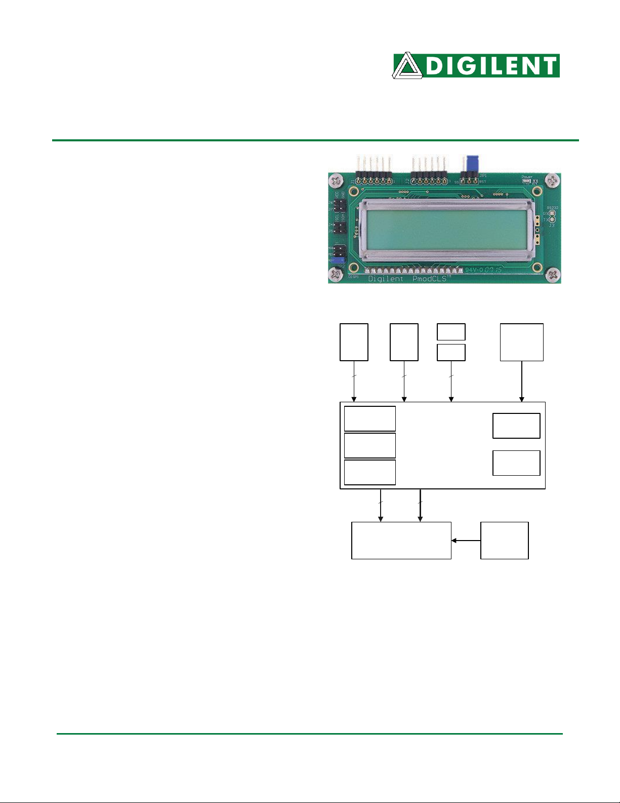
Overview
The PmodCLS module can be used to display
important information during program
development or as a user interface after the
project has been completed. The module is
ideally suited for projects that include a Digilent
embedded-AVR board, but can also be used in
projects using a Digilent FPGA board.
The module is capable of executing a variety of
instructions, such as erasing specific
characters, setting different display modes,
scrolling, and displaying user-defined
characters. These instructions are specified
using escape sequences to send commands to
the board’s embedded Atmel ATmega48
microcontroller. The display on the module is
driven by this AVR and controls all of the
features of the board.
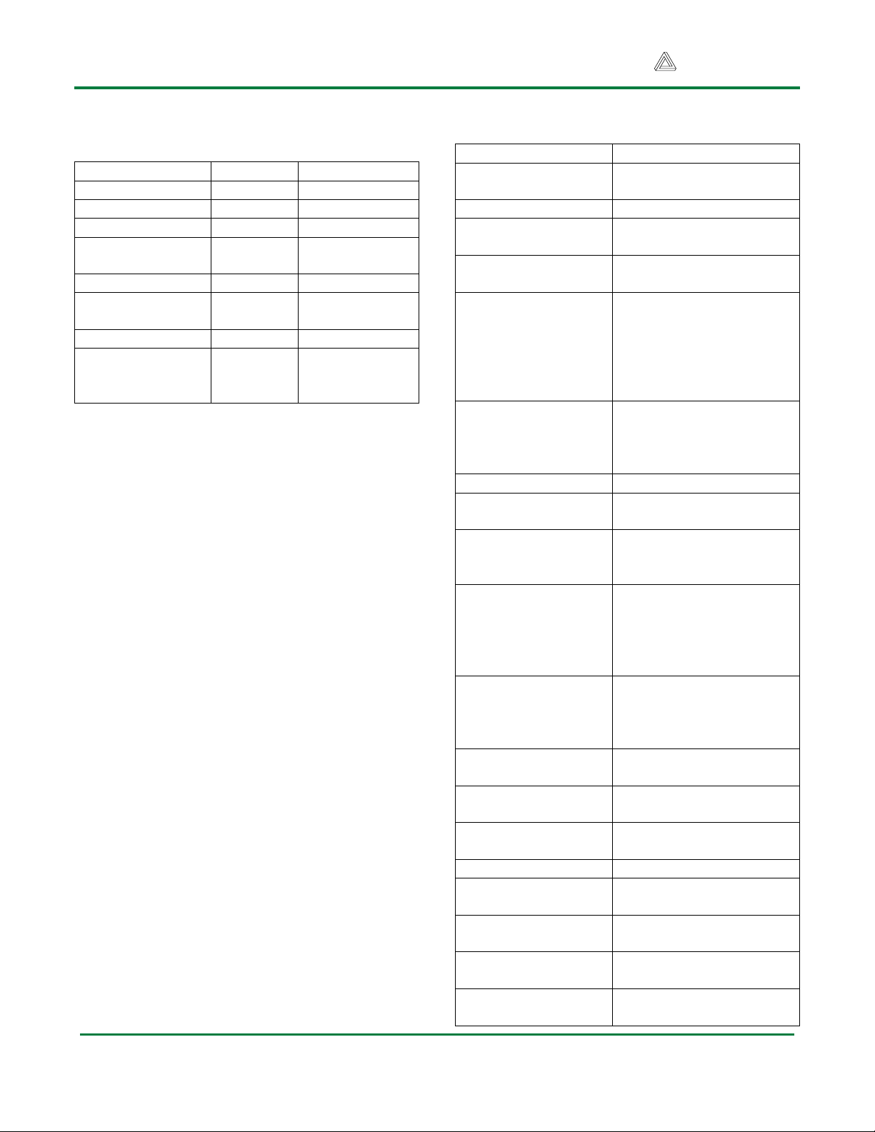
Functional Description
Communication with the embedded AVR on
the PmodCLS is established using a UART,
SPI, or TWI (Phillips I²C compatible) serial
connection. Characters are written to the
display simply by sending characters over the
communication link. The characters appear on
the display at the current location of the
board’s cursor.
You set the cursor location, and send other
instructions, by sending escape sequences. An
escape sequence is specified by first sending
the escape character followed by a left square
bracket ‘[‘, zero or more numeric parameters
separated by semicolons ‘;’ followed by the
command character for the specific command..
All of the possible instructions are listed in the
”Instruction Set” section, below.
PmodCLS Block Diagram
Communication Options
You can set the board’s communication
method by setting the mode jumpers MD0,
MD1, and MD2 on the board. Possible mode
jumper configurations are listed in the table
below. For Rev D boards, a missing jumper is
represented by 0 and a connected jumper is
represented by 1. For Rev E boards, a missing
Doc: 502-092 page 1 of 4
Copyright Digilent, Inc. All rights reserved. Other product and company names mentioned may be trademarks of their respective owners.
Page 2
PmodCLS Reference Manual
Digilent, Inc.
www.digilentinc.com
MD2, MD1, MD0
Protocol
Details
0,0,0
UART
2400 baud
0,0,1
UART
4800 baud
0,1,0
UART
9600 baud
0,1,1
UART
baud rate in
EEPROM
1,0,0
TWI
address: 0x48
1,0,1
TWI
address in
EEPROM
1,1,0
SPI
1,1,1
specified
in
EEPROM
specified in
EEPROM
Instruction
Result
<row>;<col>H
set cursor position to
<row>,<col>
s
save cursor position
u
restore saved cursor
position
j
clear display and home
cursor
<ps>K
erase within line
0 = current position to
end of line
1 = start of line to
current position
2 = entire line
<ps>N
erase field in current line
<ps> = number of chars
starting at current
position
<pn>@
scroll left <pn> columns
<pn>A
scroll right <pn>
columns
*
reset; equivalent to
cycling power of
PmodCLS
<ps>h
set display mode
0 = wrap line at 16
characters
1 = wrap line at 40
characters
<ps>c
set cursor mode
0 = cursor off
1 = cursor on, blink off
2 = cursor on, blink on
<pn>a
save TWI address in
EEPROM to <pn>
<pn>b
save baud rate value in
EEPROM to <pn>
<pt>p
program character table
into LCD
Instruction
Result
<pt>t
save RAM character
table to EEPROM
<pt>l
load EEPROM
character table to RAM
<pn>…<pn>;<ps>d
define user
programmable character
<ps>m
save communication
mode to EEPROM
jumper is represented by 1 and a connected
jumper is represented by 0.
Connector J1 is used for SPI communication.
Connector J2 can either be used for UART or
TWI communication. Connectors J4 and J5
can be used to daisy chain other TWI devices.
Power Supply Options
The module is rated for external power ranging
from 2.7 to 5.5 volts DC. Using voltage outside
this range could damage the PmodCLS and
connected devices. The PmodCLS can be
powered through the board’s 6-pin headers J1
or J2, or through connectors J6 or J7.
When the module is connected to another
Digilent microcontroller or FPGA board, that
board can power the PmodCLS through a
Pmod connector. The host board should be
jumpered to provide 3.3V on the VCC pin of
the connector being used. The module is then
powered by the host board’s power supply.
Instruction Set
The PmodCLS is capable of executing many
different instructions. Instructions are sent
using escape sequences. An escape sequence
begins with the ESC character (character code
0x1B or decimal 27), followed by the left
square bracket ‘[‘ , followed by 0 or more
parameters separated by semicolons ‘;’ and
ending with the command character.
Command characters are case sensitive.
www.digilentinc.com page 2 of 4
Copyright Digilent, Inc. All rights reserved. Other product and company names mentioned may be trademarks of their respective owners.
Page 3

PmodCLS Reference Manual
Digilent, Inc.
www.digilentinc.com
w
enable write to
EEPROM
<ps>n
save cursor mode to
EEPROM
<ps>o
save display mode to
EEPROM
Symbol
Definition
<pr>
row number (0 - 1)
<pc>
column number (0 – 39)
<pn>
numeric parameter
(decimal, hex, or binary)
<ps>
decimal selection
parameter
<pt>
character table selector
(0 – 2 in EEPROM, 3 in
RAM)
Connector J1 – SPI Communications
Pin
Signal
Description
1
SS/RST
Slave Select
2
MOSI
Master out/Slave in Data
3
MISO
Master in/ Slave out Data
4
SCK
Serial Clock
5
GND
Power supply ground
6
VCC
Power supply (3.3V)
EEPROM
Before you can store any value to an address
in EEPROM, writing to EEPROM must first be
enabled. The command to enable writing to
the EEPROM must be sent before each
successive write to EEPROM. If the command
to enable writing to the EEPROM is not sent
before an EEPROM-related command, the
command will be ignored.
Custom Characters
The module can display up to eight custom
characters at a time, but is capable of storing
four sets of eight characters. This consists of
three stored character tables in EEPROM and
one table loaded into the LCD’s RAM.
To create a new custom character, send the
command (ESC)[<pn>…<pn>;<ps>d where
<pn> is a numeric parameter that describes a
row in the character and <ps> is a decimal
selection parameter (0 through 7.) A custom
character definition contains eight rows, so the
escape sequence to define one must have
eight <pn> values followed by the <ps> value
that specifies the character being defined.
To create a new character, first draw out the
pattern. Then, determine the numerical value
of each row in the character. Note that the leftmost segment is the most significant bit.
Record each row, from top to bottom, and
record which character in the table to save it
to. Each row of the character contains six
pixels, so only the low six bits of each byte
value are used.
For example, the following character would be
saved by writing:
lcdChar(0x1B);
lcdString("[14;31;21;31;23;16;31;14;0d");
where lcdChar( ) and lcdString( ) are functions
that write characters and arrays of characters.
The above command saves the character to
the ‘0’ address in the LCD’s RAM table. To
display this character, send the numerical
value of the addressed character. In this
example, it is performed by writing
lcdChar(0x00);
The character will appear at the location of the
LCD’s cursor.
www.digilentinc.com page 3 of 4
Copyright Digilent, Inc. All rights reserved. Other product and company names mentioned may be trademarks of their respective owners.
Page 4

PmodCLS Reference Manual
Digilent, Inc.
www.digilentinc.com
Connector J2 – UART/TWI Communications
Pin
Signal
Description
1
SCL
TWI clock
2
SDA
TWI data
3
TXD
UART transmit data
4
RXD
UART receive data
5
GND
Power supply ground
6
VCC
Power supply (3.3V)
Connector J4 & J5 – TWI Daisy Chain
Pin
Signal
Description
1
SCL
TWI clock
2
SDA
TWI data
www.digilentinc.com page 4 of 4
Copyright Digilent, Inc. All rights reserved. Other product and company names mentioned may be trademarks of their respective owners.
 Loading...