

Page 1
1300 Henley Court
Pullman, WA 99163
509.334.6306
www.digilentinc.com
PmodCLS™ Reference Manual
Revised April 8, 2016
This manual applies to the PmodCLS rev. D-E
DOC#: 502-092
Copyright Digilent, Inc. All rights reserved.
Other product and company names mentioned may be trademarks of their respective owners.
Page 1 of 3
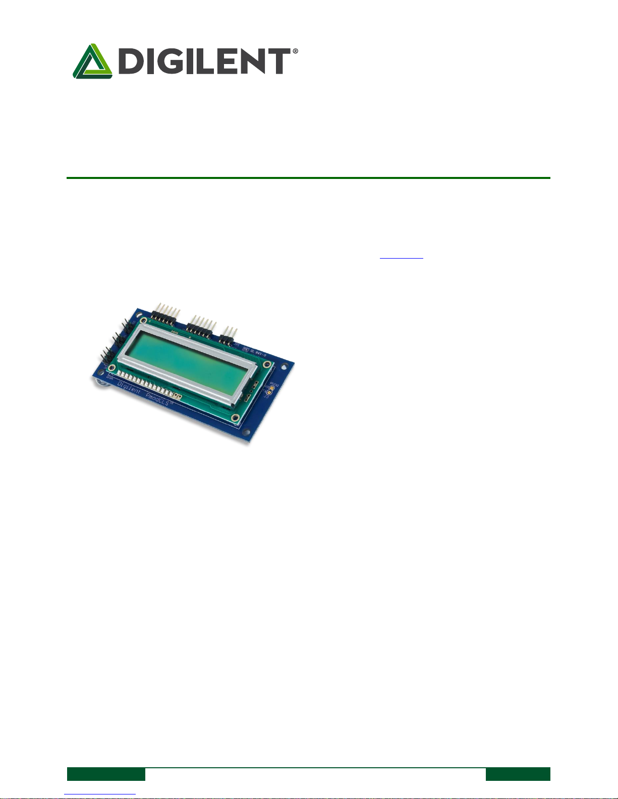
The PmodCLS.
16×2 liquid crystal character display
Wide range of instruction functions
Up to 32 user definable characters
Multiple communication options including
UART, SPI, and I²C
Small PCB size for flexible designs 1.8“ ×
3.8” (4.6 cm × 9.7 cm)
Two 1×6-pin Pmod ports with SPI and UART
interfaces
Library and example code available in
resource center
Features include:
Overview
The Digilent PmodCLS is a 16x2 character LCD module driven by an Atmel® ATmega48 microcontroller.
1 Functional Description
The PmodCLS module can be used to display important information during program development or as a user
interface after the project has been completed. The module is ideally suited for microcontroller boards but can
also be used in projects using a FPGA board.
The module is capable of executing a variety of instructions such as erasing specific characters, setting different
display modes, scrolling, and displaying user-defined characters. These instructions are specified using escape
sequences to send commands to the board’s embedded Atmel ATmega48 microcontroller. The display on the
module is driven by this AVR and controls all of the features of the board.
2 Interfacing with the Pmod
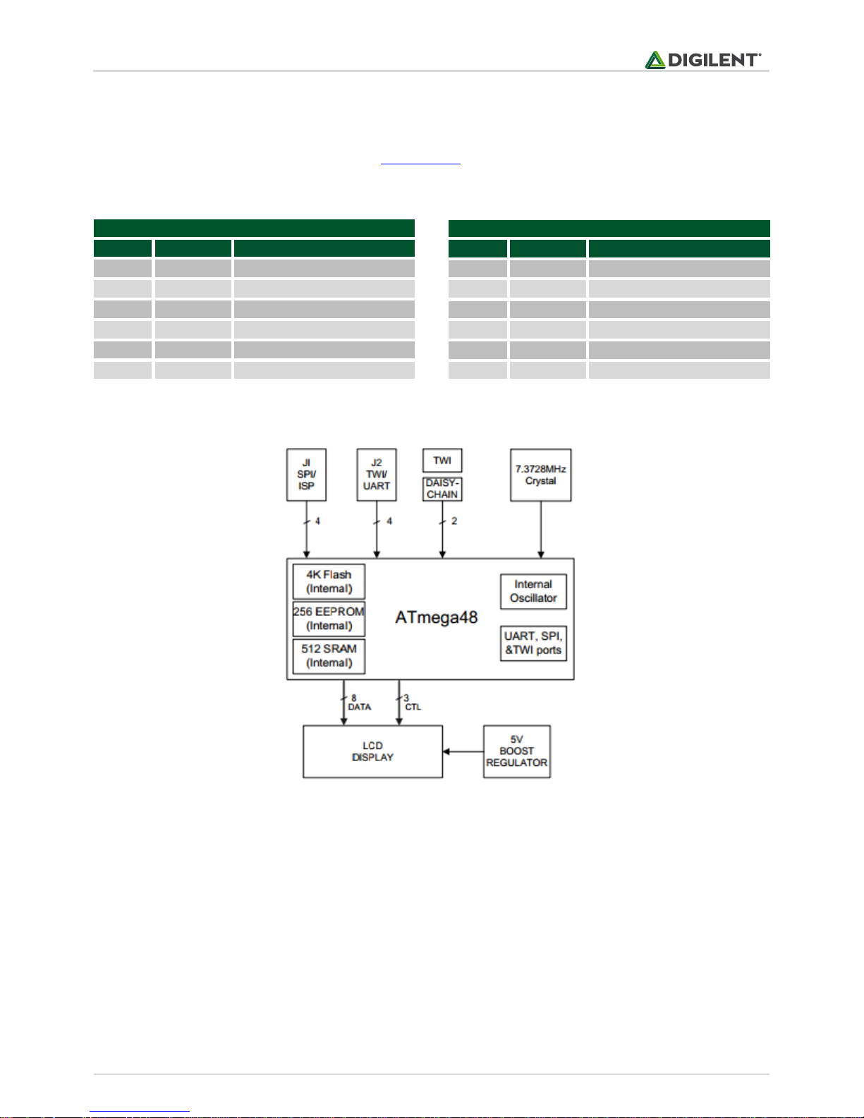
The PmodCLS can communicate with the host board through the SPI, I2C, and UART ports.
Page 2
PmodCLS™ Reference Manual
Copyright Digilent, Inc. All rights reserved.
Other product and company names mentioned may be trademarks of their respective owners.
Page 2 of 3
Header J1
Pin
Signal
Description
1
SS
Slave Select
2
MOSI
Master-Out-Slave-In
3
MISO
Master-In-Slave-Out
4
SCK
Serial Clock
5
GND
Power Supply Ground
6
VCC
Positive Power Supply (3.3V)
Header J2
Pin
Signal
Description
1
SCL
Serial Clock
2
SDA
Serial Data
3
TXD
Transmit Data
4
RXD
Receive Data
5
GND
Power Supply Ground
6
VCC
Positive Power Supply (3.3V)
Table 1. J1 pinout description table.
Table 2. J2 pinout description table.
Through these protocol standards, users are able to set the cursor location and send other instructions by sending
escape sequences. And escape sequence is specified by first sending the escape character (0x1B) followed by a left
square bracket '[' (0x5B), and then one or more numeric parameters followed by the command character for the
specific command. Feel free to use our provided example code.
Figure 1. PmodCLS block diagram.
2.1 Communication Protocol Selection
You can set the board's communication method by setting the mode jumpers MD0, MD1, and MD2 on the board.
Possible mode jumper configurations are listed in Table 3 below. For rev. D boards, a missing jumper is
represented by a '0' and a connected jumper is represented by '1'. For rev. E boards, a missing jumper is
represented by a '1' and a connected jumper is represented by a '0'.
Page 3

PmodCLS™ Reference Manual
Copyright Digilent, Inc. All rights reserved.
Other product and company names mentioned may be trademarks of their respective owners.
Page 3 of 3
MD2, MD1, MD0
Protocol
Details
0,0,0
UART
2400 baud
0,0,1
UART
4800 baud
0,1,0
UART
9600 baud
0,1,1
UART
Baud rate in EEPROM
1,0,0
TWI
Address: 0x48
1,0,1
TWI
Address in EEPROM
1,1,0
SPI
1,1,1
Specified in EEPROM
Specified in EEPROM
Table 3. Mode jumper configurations.
Any external power applied to the PmodCLS must be within 2.7V and 5.5V; if you are powering the Pmod from its
VCC pin, you must operate the Pmod at 3.3V in order for the on-board step-up switching regulator to work
correctly.
3 Physical Dimensions
The pins on the pin header are spaced 100 mil apart. The PCB is 1.8 inches long on the sides parallel to the pins on
the pin header and 3.8 inches long on the sides perpendicular to the pin header.
Page 4

Mouser Electronics
Authorized Distributor
Click to View Pricing, Inventory, Delivery & Lifecycle Information:
Digilent:
410-092P 410-092
 Loading...