

Page 1
PPmmooddLLSS11™™
IInnffrraarreedd LLiigghhtt DDeetteeccttoorr MMoodduullee
RReeffeerreennccee
Revision: August 14, 2007
Note: This document applies to REV A of the board.
Overview
The PmodLS1 module is an interface module
for connecting optical sensors to digital inputs
on a Digilent system board. When used with
reflective infrared light detector sensors
(available from Digilent), the PmodLS1 is
ideally suited for use in line-sensing robots. It
is also well-suited for use as a general-purpose
interface for either reflective or transmissive
photo detectors.
The module can be used with Digilent
microcontroller boards or Digilent FPGA
boards.
Functional Description
The PmodLS1 is designed to be used with
sensors containing an infrared LED and an
infrared-sensitive photo-transistor. The
module supports up to four sensors connected
at the S1, S2, S3, and S4 headers. Digilent
has reflective-type sensors available for use
with the PmodLS1. When using Digilent’s
sensors, refer to the print on the board for the
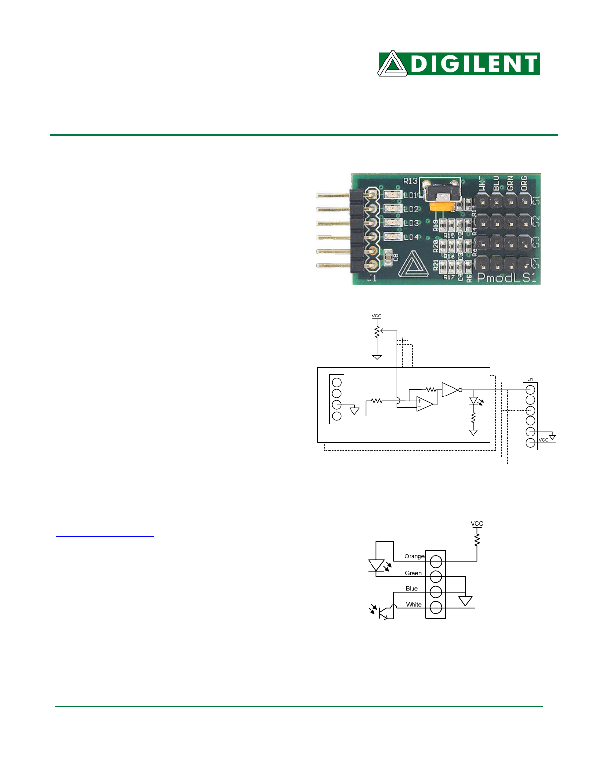
orientation of the wire. If third-party sensors
are used, refer to the connection diagram in
figure 2 or the board schematic available at
www.digilentinc.com
of the LED and photo-transistor.
The PmodLS1 uses the VCC pin (pin 6) of the
Pmod connector J1 to power the infrared
LEDs. The module uses analog comparators
to determine when the infrared detectors have
sensed more infrared light than the threshold
limit. The sensitivity of the sensors can be
adjusted by adjusting the onboard
potentiometer.
MMaannuuaall
for the proper connection
Figure 2 Sensor Connection Diagram
www.digilentinc.com
215 E Main Suite D | Pullman, WA 99163
(509) 334 6306 Voice and Fax
Figure 1 PmodLS1 Circuit Diagram
®
Doc: 502-086 page 1 of 2
Copyright Digilent, Inc. All rights reserved. Other product and company names mentioned may be trademarks of their respective owners.
Page 2

PmodLS1 Reference Manual
The PmodLS1 is equipped with onboard LEDs
that are used as visual indicators of the status
of the four available sensors inputs. When a
sensor is picking up more infrared light than
the threshold limit, the corresponding LED will
be illuminated and the corresponding output
pin on J1 will output a logic 1. If the sensor is
picking up less light than the threshold limit,
the corresponding LED will be off and the
corresponding output pin on J1 will output a
logic 0.
Digilent, Inc.
www.digilentinc.com
www.digilentinc.com page 2 of 2
Copyright Digilent, Inc. All rights reserved. Other product and company names mentioned may be trademarks of their respective owners.
 Loading...