

Page 1
DDiiggiilleenntt PPmmooddSSWWTT™™ SSwwiittcchh
®
MMoodduullee BBooaarrdd RReeffeerreennccee MMaan
Revision: 06/07/05
nuuaall
Overview
The Digilent PmodSWT Switch Module Board
(the SWT™) has four slide switches that can
be used to provide “on and off” inputs to a
circuit.
Features include:
• four slide switches with series resistors
• one 6-pin header
• small form factor (1.30” x 0.80”).
Functional Description
The SWT’s switches can be used as mode
switches and also as data input switches. They
can be activated separately or together in any
combination.
When the switch is in the up position it sends
the voltage on the VCC pin to the
corresponding pin on J1, and when the switch
is in the down position it sends GND to the
corresponding pin on J1.
The SWT has a 6-pin header for easy
connection to a Digilent system board. Some
system boards, like the Digilent Pegasus
board, have a 6-pin header that can connect to
the SWT with a 6-pin cable.
To connect the SWT to other Digilent system
boards, a Digilent Modular Interface Board
(MIB) and a 6-pin cable may be needed. The
MIB plugs into the system board, and the cable
connects the MIB to the SWT.
www.digilentinc.com
215 E Main Suite D | Pullman, WA 99163
(509) 334 6306 Voice and Fax
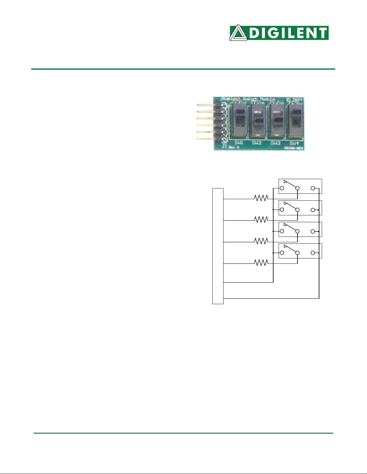
SW1
P1
SW2
P2
SW3
P3
SW4
P4
J1 Connector
GND
Vcc
Switch Module Circuit Di agram
Doc: 502-083 page 1 of 1
Copyright Digilent, Inc. All rights reserved. Other product and company names mentioned may be trademarks of their respective owners.
 Loading...