

Page 1
DDiiggiilleenntt PPmmooddTTPPHH TTeesstt PPooiinntt
®
HHeeaaddeerr BBooaarrdd RReeffeerreennccee
Revision: 4/12/05
Overview
The Digilent PmodTPH Test Point Header
Module Board (the TPH) is an ideal way to test
the connection between a Pmod™ and system
board. It simply passes signals from the J1
connector to the J2 connector, providing testpoint access via the J2 header.
Features include:
• two 6-pin pass-through headers
• a 6-pin test point header
• small form factor (1.00” x 0.80”).
Functional Description
The TPH has a right-angle 6-pin header and
right-angle 6-pin connector so that it can be
inserted easily between a system board and
Pmod board. A vertical 6-pin header in the
center of the board allows test measurement
probes to be attached easily.
Each prong on the test point header
corresponds to the connection formed by the
two devices through the TPH’s 6-pin header
and connector.
The TPH allows for testing and debugging
individual connections using an oscilloscope,
voltmeter, or logic analyzer.
The TPH has a 6-pin header for easy
connection to a Digilent system board. Some
system boards, like the Digilent Pegasus
board, have a 6-pin header that can connect to
the TPH with a 6-pin cable.
To connect the TPH module to other Digilent
system boards, a Digilent Modular Interface
Board (MIB) and a 6-pin cable may be needed.
The MIB plugs into the system board, and the
cable connects the MIB to the TPH.
MMaannuuaall
www.digilentinc.com
215 E Main Suite D | Pullman, WA 99163
(509) 334 6306 Voice and Fax
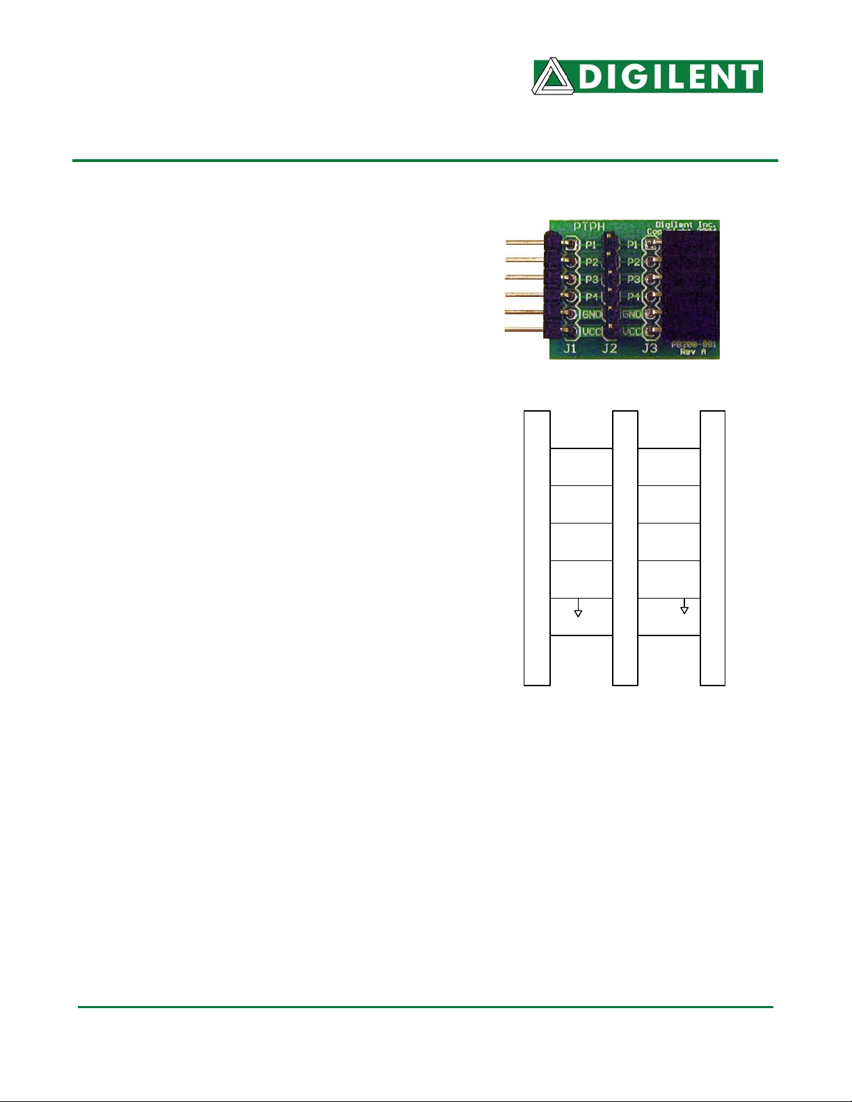
GNDGND
Vcc
P1
P2
P3
P4
J3 Connector
P1
P2
P3
P4
J1 Connector
J2 Test Point Header
Vcc
Test Point Header Diagram
Doc: 502-081 page 1 of 1
Copyright Digilent, Inc. All rights reserved. Other product and company names mentioned may be trademarks of their respective owners.
 Loading...