

Page 1
DDiiggiilleenntt PPmmooddRRSS223322™™
®
CCoonnvveerrtteerr MMoodduullee BBooaarrdd
RReeffeerreennc
Revision: 04/12/05
cee MMaannuuaall
www.digilentinc.com
215 E Main Suite D | Pullman, WA 99163
(509) 334 6306 Voice and Fax
Overview
The PmodRS232 Converter Module Board (the
RS232 module) translates voltage from the
logic levels used by Digilent system boards to
the RS232 voltage used for serial
communications.
The RS232 module creates a two-way I/O
exchange by converting RS232 voltage to logic
level voltage and converting logic voltage to
RS232 voltage. RS-232 voltage levels are -3 to
-12V for a logic ‘1’, and +3 to +12 for a logic ‘0’.
The RS232 module is configured as a data
communications equipment (DCE) device. It
connects to data terminal equipment (DTE)
devices, such as the serial port on a PC, using
a straight-through cable.
Features include:
• Max3223 integrated circuit
• a DB9 connector and 6-pin header
• transmit and receive functions
• small form factor (1.00” x 1.30”).
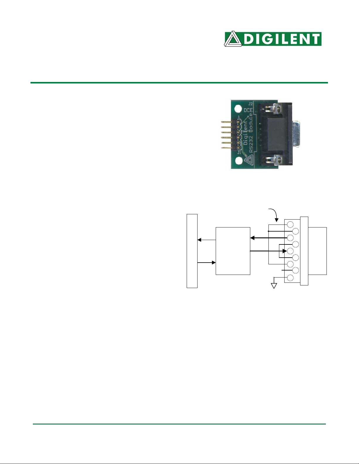
J 1 Connect o r
Functional Description
The RS232 module is configured as a 3-wire
DTE serial port, with one wire carrying transmit
data, one receive data, and the third signalground. The module converts logic signals
arriving on J1 pin 4 to RS-232 voltage, and
RS-232 voltage signals arriving on the DB-9
pin 2 to logic levels.
The RS232 module has a 6-pin header for
easy connection to a Digilent system board.
Some system boards, like the Digilent Pegasus
board, have a 6-pin header that can connect to
the RS232 module with a 6-pin cable. To
connect the RS232 module to other Digilent
Doc: 502-068 page 1 of 1
Copyright Digilent, Inc. All rights reserved. Other product and company names mentioned may be trademarks of their respective owners.
system boards, a Digilent Modular Interface
Board (MIB) and a 6-pin cable may be needed.
The MIB plugs into the system board, and the
cable connects the MIB to the RS232 module.
Pi ns 1,4, 6 and 7,8 are
ti ed for handshaki ng .
P3
RXD
MAX3223
P4
TXD
RS-232
Level
Converter
RS232 Circuit Diagram
NC
1
6
2
7
3
8
4
9
5
DB9
DCE Connector
 Loading...