

Page 1
DDiiggiilleenntt PPmmooddDDIINN11™™ DDiiggiittaall
®
IInnppuutt MMoodduullee RReeffeerreennccee M
Revision: 4/12/05 215 E Main Suite D | Pullman, WA 99163
Maannuuaall
www.digilentinc.com
(509) 334 6306 Voice and Fax
Overview
The Digilent PmodDIN1 Digital Input Module
Board (the DIN1™) debounces digital input
signals so they can be used directly by a
Digilent system board. The DIN1 can receive
signals from switches, sensor devices, or any
other standard logic inputs.
Features include:
• four digital-input channels with ESD
protection diodes
• four debouncing filters with Schmitttrigger inverters
• a 6-pin header and 6-pin connector
• small form factor (0.80” x 0.80”).
Functional Description
Inputs to the DIN1 are debounced to eliminate
multiple signal transitions that may be caused
by inputs arising from noisy or “bouncing”
sources like buttons and switches. Each of the
DIN1’s four channels has an analog filter
consisting of two resistors and a capacitor, with
a time constant of approximately one
millisecond. The filters absorb and diffuse
signal noise before it can reach the threshold
needed to activate the Schmitt-trigger
inverters. The Schmitt-trigger inverters ensure
signals transition quickly and cleanly between
low and high logic levels.
The four signal inputs can be used individually
or any of them can be used simultaneously.
The DIN1 has two protection diodes that
prevent damage to the inverter from
overvoltage (for example, from an ESD
discharge). The protection diodes are on the
input side of each channel and clamp voltage
input to VCC or ground. The diodes allow for a
maximum safe continuous current of 15mA
and a safe voltage range between -6V and
10V.
Doc: 502-067 page 1 of 1
Copyright Digilent, Inc. All rights reserved. Other product and company names mentioned may be trademarks of their respective owners.
A resistor is also installed on the output side of
each channel to protect the DIN1 from
conflicting output voltages.
The DIN1 can receive signals from switches
and standard logic inputs. To use standard
logic inputs, it is necessary to sink at least one
mA of current in order to drive the module.
The DIN1 has a 6-pin header for easy
connection to a Digilent system board. Some
system boards, like the Digilent Pegasus
board, have a 6-pin header that can connect to
the DIN1 with a 6-pin cable. To connect the
DIN1 to other Digilent system boards, a
Digilent Modular Interface Board (MIB) and a
6-pin cable may be needed. For more
information, see www.digilentinc.com
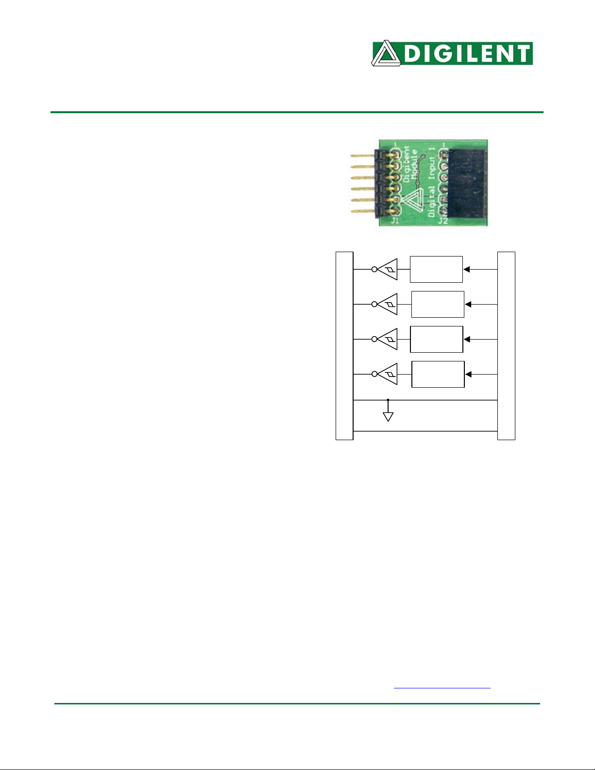
J1 Connector
P1
P2
P3
P4
GND
Vcc
DIN1 Circuit Diagram
Debounce
filter
Debounce
filter
Debounce
filter
Debounce
filter
P1
P2
P3
P4
J2 Connector
 Loading...