

Page 1
DDiiggiilleenntt PPmmooddCCOONN11™™ MMoodduullee
®
BBooaarrdd RReeffeerreennccee MMaannuuaall
Revision: 4/12/05
Overview
The Digilent PmodCON1Module Board (the
CON1™) is designed for use with a Digilent
system board and conveys I/O signals
between six screw terminals and a 6-pin
header connection. Two of the terminals can
be used to provide power from an outside
source, and the other four can be used for data
signals.
The CON1 can be easily attached to a Digilent
system board using a Digilent Modular
Interface Board (MIB) and a six-pin cable.
Signals from an outside device can be
attached to the CON1 using the screw
terminals.
Features include:
• a 6-pin header
• six screw terminals
• small form factor (1.10” x 0.80”).
Functional Description
The CON1 allows input and output to travel
between screw terminals and a 6-pin header.
Each pin has a corresponding screw terminal.
There is a terminal for ground, one for voltage,
and the remaining four can be used to connect
to outside devices.
The CON1 has a 6-pin header for easy
connection to a Digilent system board. Some
system boards, like the Digilent Pegasus
board, have a 6-pin header that can connect to
the CON1 with a 6-pin cable. To connect the
CON1 to other Digilent system boards, a
Digilent Modular Interface Board (MIB) and a
6-pin cable may be needed. The MIB plugs
into the system board, and the cable connects
the MIB to the CON1.
www.digilentinc.com
215 E Main Suite D | Pullman, WA 99163
(509) 334 6306 Voice and Fax
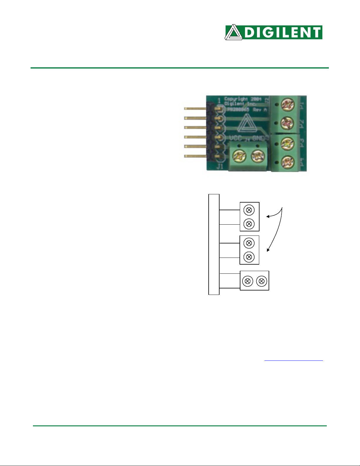
Terminal
P1
P2
P3
P4
J1 Connection
GND
VCC
CON1 Circui t D iagram
For more information see www.digilentinc.com
Blocks
.
Doc: 502-065 page 1 of 1
Copyright Digilent, Inc. All rights reserved. Other product and company names mentioned may be trademarks of their respective owners.
 Loading...