

Page 1
DDiiggiilleenntt PPmmooddDDAA11™™ DDiiggiittaall TToo
®
AAnnaalloogg MMoodduullee CCoonnvveerrtte
RReeffeerreennccee MMaannuuaall
Revision: 04/12/05
err BBooaarrdd
Overview
The Digilent PmodAD1 Digital to Analog
Module Converter module (the DA1™)
converts signals from digital to analog at up to
one MSa per second. The DA1 uses a 6-pin
header connector and at less than one square
inch is small enough to be located where the
reconstructed signal is needed.
Features include:
• two AD7303 8-bit D/A converter chips
that convert up to one MSa per second
• a 6-pin header and 6-pin connector
• four D/A conversion channels
• very low power consumption
• small form factor (0.80” x 0.80”).
Functional Description
The DA1 can produce an analog output
ranging from 0-3.3 volts. It has four
simultaneous D/A conversion channels, each
with an 8-bit converter that can process
separate digital signals.
The DA1 is equipped with two AD7303 digital
to analog converters. Each converter has two
channels through which digital signals can be
converted to analog signals.
Outputs are produced by sending commands
via the SPI/MICROWIRE™ serial bus to the
D/A converters. The two converters are
connected in parallel so that commands are
sent to both converters simultaneously.
The DA1 is designed to work with Digilent
system boards. Some system boards, like the
Digilent Pegasus board, have a 6-pin header
that can be connected to the DA1’s 6-pin
header using a 6-pin cable.
www.digilentinc.com
215 E Main Suite D | Pullman, WA 99163
(509) 334 6306 Voice and Fax
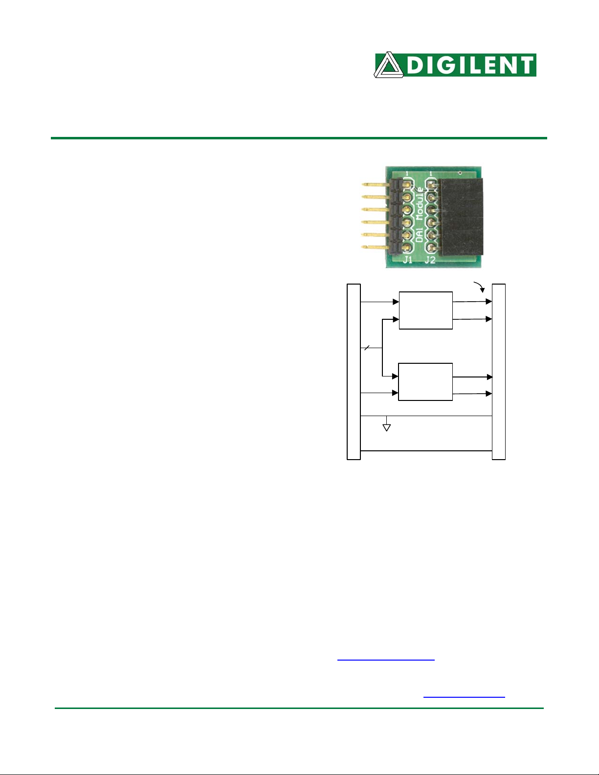
Analog Outputs
D1
2
D2
J1 Connector
GND
VCC
Other Digilent boards may need a Digilent
Modular Interface Board (MIB) and a 6-pin
cable to connect to the DA1. The MIB plugs
into the system board and the cable connects
the MIB to the DA1.
The DA1 can be powered by voltage from
either a Digilent system board or an outside
device. Damage can result if power is supplied
from both sources or if the outside device
supplies more than 3V. For more information,
see www.digilentinc.com
For information on the AD7303, see the Analog
Devices data sheet at www.analog.com
AD7303
D/A
Converter
Sync,
Clock
AD7303
D/A
Converter
DA1 Circuit Diagram
.
J2 Connector
.
Doc: 502-063 page 1 of 1
Copyright Digilent, Inc. All rights reserved. Other product and company names mentioned may be trademarks of their respective owners.
 Loading...