

Page 1
DDiiggiilleenntt CC--MMoodd™™ BBooaarrddss
RReeffeerreennccee MMaannuuaal
Revision: June 4, 2004 215 E Main Suite D | Pullman, WA 99163
l
www.digilentinc.com
(509) 334 6306 Voice and Fax
Overview
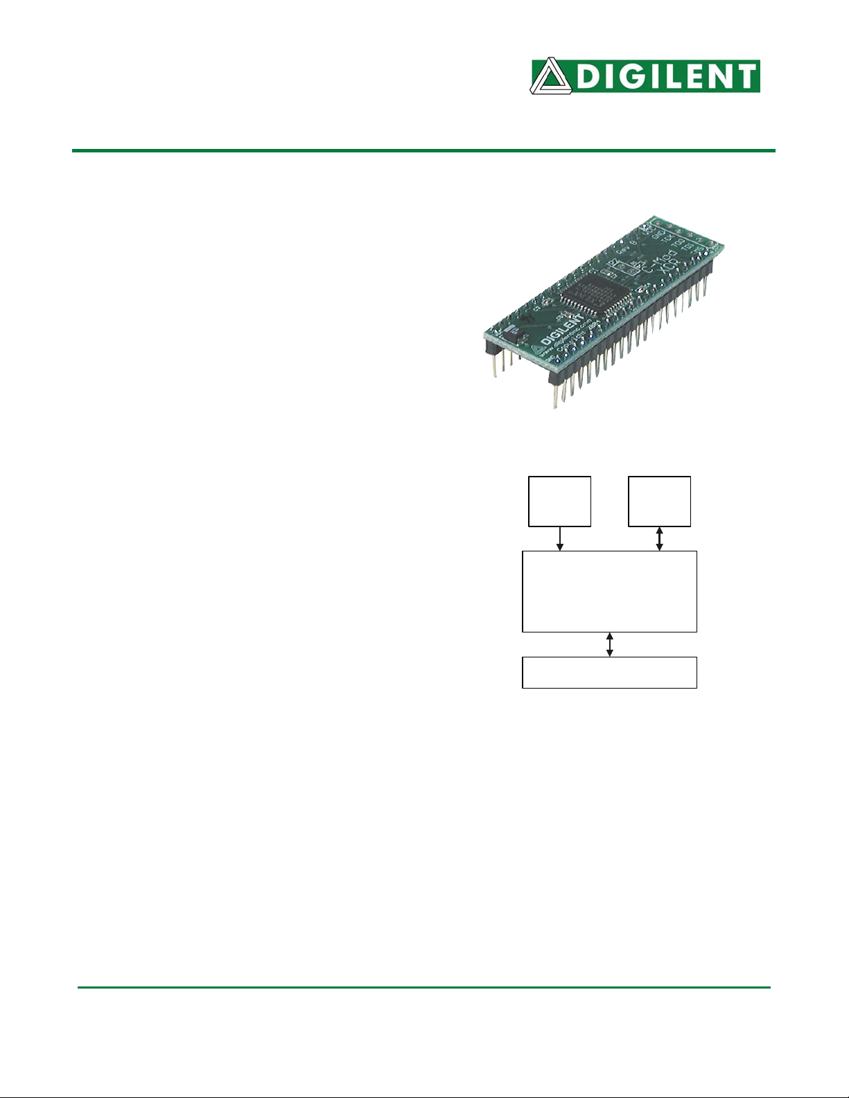
C-Mod boards combine a Xilinx CPLD, a JTAG
programming port, and power supply circuits in
a convenient 600-mil, 40-pin DIP package. CMods are ideally suited for breadboard or other
prototype circuit designs where the use of
small surface mount packages is impractical.
All C-Mod boards include:
• A single 3.3V supply voltage (voltage
regulation provided on C-Mod board where
required);
• Adequate bypass capacitance on all CPLD
voltage supply pins;
• All available user I/O signals brought out to
Figure 1. C-Mod XCR module
1.8VDC
regulator
(C2 Mod)
JTAG
Connector
DIP pins;
• Once programmed, CPLD designs are nonvolatile;
• Designs can easily be ported between CMods using different CPLD device families;
• All C-Mod boards are compatible with the
CPLD in VQ44 Package
CMod-XCR: XCR3064XL
CMod-C2: XC2C64
CMod-95: XC9572XL
free Xilinx WebPack tools.
C-Mods were created to make the latest Xilinx
CPLDs more practical for experimental and
prototype circuits. They can plug directly in to
Figure 2. C-Mod circuit board block diagram
40 pin, 600-mil DIP Connector
breadboards or IC sockets, and they can mate
with the Digilent Ceres™ board to utilize a
collection of ready-made I/O circuits. C-Mods
are available with CoolRunner-II CPLDs (CMod C2), CoolRunner CPLDs (C-Mod XCR),
and XC95 CPLDs (C-Mod 95). C-Mod boards
are especially useful for investigating designs
across a variety of CPLD families.
Functional Description
C-Mod boards, which measure just 0.7” by
2.16”, allow designers to experiment with
CPLD-based designs in a variety of state-of-
the art devices. Designs can easily be ported
from one C-Mod to another, so that design
performance in different devices can be
compared and contrasted. The 40-pin DIP form
factor allows C-Mods to be used in breadboard
or other through-hole circuits where surfacemount devices are impractical. They can be
configured with a wide range logic circuits,
from simple logic functions to sequential
controllers. All available CPLD I/O signals are
routed to the 40-pin DIP connections.
®
Doc: 502-047 page 1 of 3
Copyright Digilent, Inc. All rights reserved. Other product and company names mentioned may be trademarks of their respective owners.
Page 2
Digilent C-Mod Reference Manual Digilent, Inc.
When used in conjunction with the Ceres
board, C-Mods can be used to rapidly
implement CPLD based circuits, or to gain
exposure to Xilinx CAD tools and CPLDoriented design methods. The Ceres board
JTAG operations are available in a pull-down
menu made visible by right clicking on the
device graphic in the programmer window.
provides C-Mods with a power supply, a clock
source, input buttons and switches, and
various output LEDs. The Ceres/C-mod
combination makes an excellent platform for
use in teaching labs.
C-Mods are programmed with a sample design
JTAG3
Cable
6-pin
header
during manufacturing. This design, available at
the Digilent website, can be used to verify CMod/Ceres function. It also provides a simple
reference design example of a Xilinx project.
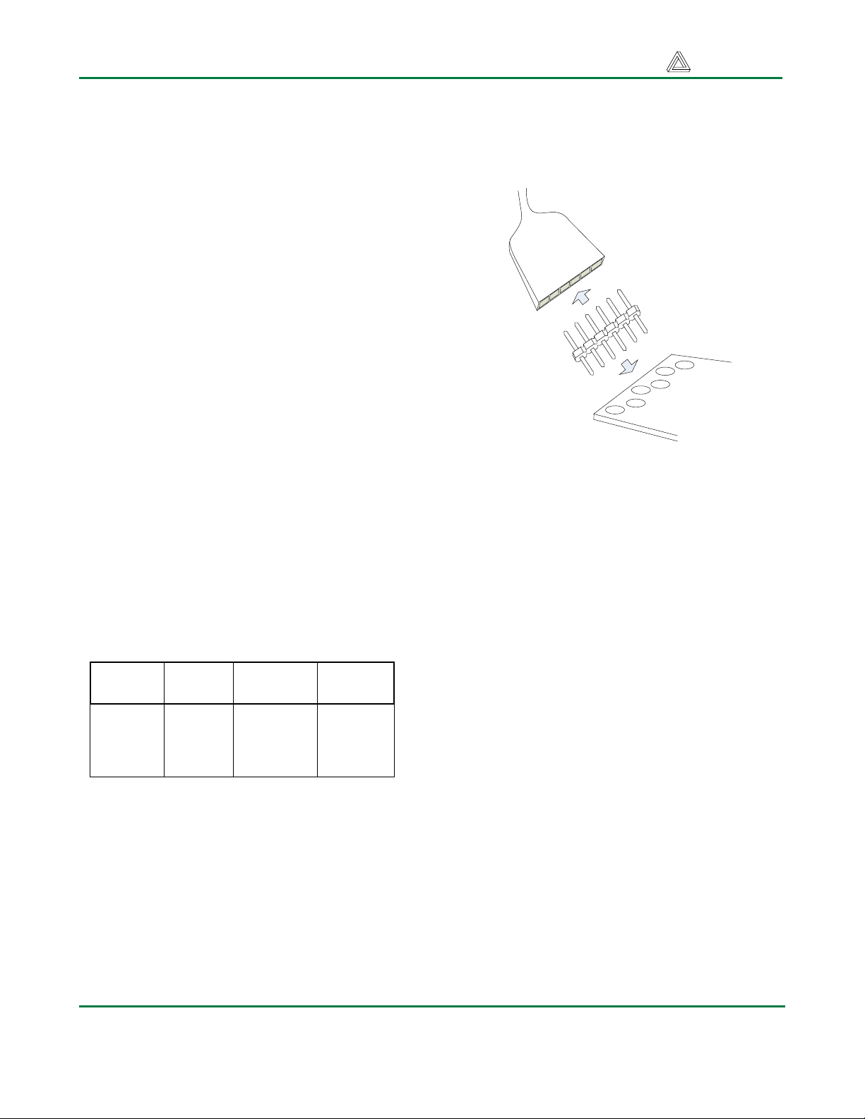
CPLD Configuration
C-Mod boards contain a JTAG port for CPLD
programming. The port consists of a pattern of
six offset holes that are not loaded with header
pins. To use this port, a row of six unattached
header pins can be inserted into the end of a
JTAG3 (or other) cable, and the other side of
the header can be inserted into the offset hole
patterns. Once the C-Mod board is connected
to the PC via the JTAG cable, the configuration
software will automatically detect the CPLD.
JTAG
Signal
TCK 11 11 26
TDI 9 9 1
TDO 24 24 32
TMS 10 10 7
XC2C64
pin
XC9572XL
pin
XCR3064
pin
Table 1. CPLD JTAG Pins
To configure the board from a computer using
the JTAG port, first ensure the C-Mod is
powered with a 3.3V supply (such as provided
by the Ceres board), and that the JTAG cable
is properly connected to the C-Mod and to the
computer. Start the configuration program
(e.g., the iMPACT programmer available in the
Xilinx WebPack tools), and the board will be
Figure 3. JTAG cable used with C-Mod
Power Supplies
C-Mod boards require a single 3.3V supply on
pin 20, and a single GND on pin 21. Current
consumption is dependant on CPLD family,
CPLD configuration, and external circuits. In
most cases, current will be far less than
100mA, but the Xilinx data sheets for the
particular CPLD should be referenced for more
information.
CPLDs
C-Mod boards are available with CoolRunner-
2, CoolRunner (XPLA), and XC95 CPLDs. All
available CPLD I/O signals are routed to the
DIP connector, and the JTAG signals are
routed to a programming connector. CPLD
pinouts are provided in tables 2 and 3 below.
Please see the data sheets for the CPLDs
available at the Xilinx web site for more
information.
C-Mod
auto-detected. Device programming and other
www.digilentinc.com page 2 of 3
Copyright Digilent, Inc. All rights reserved. Other product and company names mentioned may be trademarks of their respective owners.
Page 3

Digilent C-Mod Reference Manual Digilent, Inc.
DIP
Ceres
PIN
Signal
XC2C64
1 CA 12 IO 4 12 IO 3 12 IO 4
2 CB 13 IO 4 13 IO 3 13 IO 4
3 CC 14 IO 4 14 IO 3 14 IO 4
4 CD 16 IO 4 16 IO 3 15 IO 4
5 7 IO 3
6
7
8
9 CE 18 IO 3 18 IO 3 18 IO 3
10 CF 19 IO 3 19 IO 4 19 IO 3
11 CG 20 IO 3 20 IO 4 20 IO 3
12 AN3 21 IO 3 21 IO 4 21 IO 3
13 AN2 22 IO 3 22 IO 4 22 IO 3
14 AN1 23 IO 3 23 IO 4 23 IO 3
15 AN0 27 IO 3 27 IO 4 25 IO 3
16 SW7 28 IO 3 28 IO 4 27 IO 1
17 DP 29 IO 3 29 IO 2
18 BTN3 30 GSR 1 30 IO 2 6 IO 2
19
20 15 VCC 26 VCCIO 9,17,29, 41 VCC
20 7,26 VCCIO 15,35 VCCINT
20 35 VAUX
21 4,17,25 GND 4,17,25 GND 16,24,36 GND
22 SW6 31 GTS2 1 31 IO 2 28 IO 1
23 SW5 32 GTS3 1 32 IO 2 30 IO 1
24 SW4 33 GTS0 1 33 GSR 1 31 IO 1
25 SW3 34 GTS1 1 34 GTS2 2 33 IO 1
26 SW2 36 IO 1 36 GTS1 2 34 IO 1
27 SW1 37 IO 1 37 IO 2 35 IO 1
28 BTN2 38 IO 1 38 IO 2 37
29 SW0 39 IO 2 39 IO 1 42 IO 2
30 LED7 40 IO 2 40 IO 1 43 IO 2
31 LED6 41 IO 2 41 IO 1 44 IO 2
32 LED5 42 IO 2 42 IO 1 2 IO 2
33 BTN0 43 GCK0 2 43 GCK1 1 40
34 BTN1 44 GCK1 2 44 GCK2 1 39
35 MCLK 1 GCK2 2 1 GCK3 1 38
36 LED4 2 IO 2 2 IO 1 3 IO 2
37 LED3 3 IO 2 3 IO 1 5 IO 2
38 LED2 5 IO 4 5 IO 3 8 IO 4
39 LED1 6 IO 4 6 IO 3 10 IO 4
40 LED0 8 IO 4 8 IO 3 11 IO 4
C-Mod C2 C-Mod 95 C-Mod XCR
XC9572XL
pin
type
Function
Block
XCR3064 pin
pin
type
Function
Block
type
IN3/CLK
3
IN0/CLK
0
IN1/CLK
1
IN2/CLK
2
Function
Block
www.digilentinc.com page 3 of 3
Copyright Digilent, Inc. All rights reserved. Other product and company names mentioned may be trademarks of their respective owners.
 Loading...