

Page 1

SSeerrvvoo RRoobboott KKiitt ((SSRRKK))
UUsseerr GGuuiidde
e
Revision: August 1, 2012
Overview
The Digilent Servo Robot Kit (SRK) provides the perfect starting point for those new to robotics, but
has the power to be used for advanced designs and applications as well. The SRK pairs our powerful
Cerebot™ MX3cK microcontroller development board with a rugged steel platform and all the motors,
wheels, and other parts needed to build a complete robot.
This document demonstrates a simple design that will get your SRK up and running, able to move
forward, backwards, and pivot left or right – all depending on which button is pressed. Using your
SRK’s powerful Cerebot MX3cK microcontroller, you’ll be able to add all sorts of functionality to your
robot. Add some of our extensive line of peripheral modules (Pmods™) and you can design almost
anything!
Your Cerebot MX3cK can be programmed with either Microchip MPLAB® IDE or chipKIT™ MPIDE.
Microchip MPLAB IDE can be downloaded for free from microchip.com. chipKIT MPIDE can be
downloaded for free from github.com/chipKIT32/chipKIT32-MAX/downloads.
The demo project used in this design can be downloaded from the Servo Robot Kit product page at
digilentinc.com. For more information on programming the Cerebot MX3cK with MPLAB or MPIDE,
see the Cerebot MX3cK Reference Manual, available from the Cerebot MX3cK product page at
digilentinc.com.
Included parts:
1300 NE Henley Court, Suite 3
Pullman, WA 99163
(509) 334 6306 Voice | (509) 334 6300 Fax
•
Cerebot MX3cK
•
standoffs for mounting MX3cK
•
battery holder (4xAA)
•
2” Velcro Strip
•
one two pin MTE battery cable
•
rugged Metal Platform with Holes on ½-inch Center
•
two continuous rotation GWS servos
•
two servo brackets
•
rugged plastic wheels and tail skid
•
two Pmod brackets
•
PmodCON3
•
PmodBTN
•
one 6” 6-pin cable
•
8/32 Machine Screws
•
8/32 Hex Machine Nuts
Doc: 516-001 page 1 of 9
Copyright Digilent, Inc. All rights reserved. Other product and company names mentioned may be trademarks of their respective owners.
Page 2
SRK Reference Manual
Functional Description
The rugged steel components have holes on ½-inch centers allowing Digilent circuit boards and other
vendors’ products to be easily attached.
The following tools are recommended for robot assembly:
• regular and small Phillips head screwdrivers
• pliers
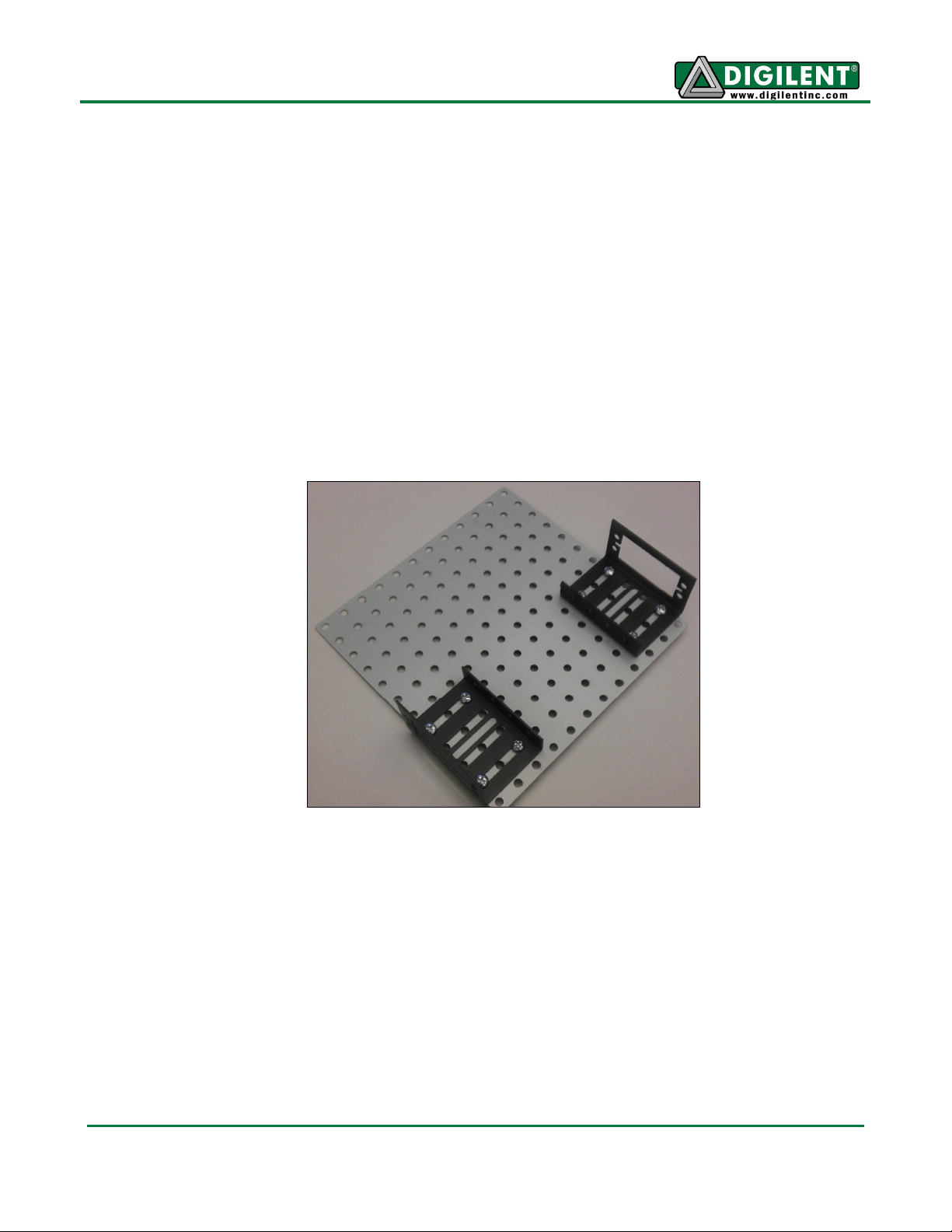
Example Assembly
1. Attach the servo brackets to the main plate as shown.
www.digilentinc.com page 2 of 9
Copyright Digilent, Inc. All rights reserved. Other product and company names mentioned may be trademarks of their respective owners.
Page 3
SRK Reference Manual
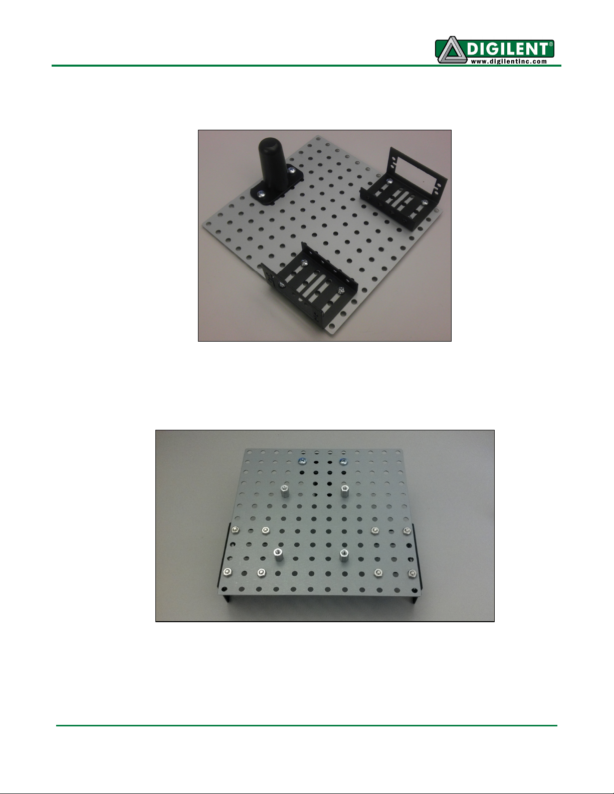
2. Attach the rear tail skid.
3. Add the standoffs to the robotic kit as shown below. Set four extra screws aside to mount the
MX3cK in a later step.
www.digilentinc.com page 3 of 9
Copyright Digilent, Inc. All rights reserved. Other product and company names mentioned may be trademarks of their respective owners.
Page 4

SRK Reference Manual
4. Attach the two Pmod clips with the hardware included in the Pmod clip bags.
5. Peel off one side of the Velcro and stick it to the main plate.
www.digilentinc.com page 4 of 9
Copyright Digilent, Inc. All rights reserved. Other product and company names mentioned may be trademarks of their respective owners.
Page 5

SRK Reference Manual
6. First, remove the white servo wheel by unscrewing the black screw, and set them aside.
Mount the servos using the remaining hardware that came with the servo mounts.
7. Take out the two wheels and the rubber traction bands. Stretch the rubber band around the
outside of the wheel. Then, attach the wheels to the servos, and secure them using the small
black screws that were removed in the previous step.
www.digilentinc.com page 5 of 9
Copyright Digilent, Inc. All rights reserved. Other product and company names mentioned may be trademarks of their respective owners.
Page 6

SRK Reference Manual
8. Attach the MX3cK to the standoffs using the four screws that were set aside in step 3. If the
through-holes on the MX3cK and the standoffs do not line up, loosen the standoffs, and retighten them after the MX3cK is attached.
www.digilentinc.com page 6 of 9
Copyright Digilent, Inc. All rights reserved. Other product and company names mentioned may be trademarks of their respective owners.
Page 7

SRK Reference Manual
9. Connect the Pmods as shown below. The PmodCON3 connects to JC 6-10 (the bottome row)
and the PmodBTN connects to JD 1-4 (the top row). Take care that the pins are all connected
in the correct orientation. See below. The symbol that looks like a flower should only be visible
on one end of the 6 pin cable, as you look down on the RDK.
10. Connect the right servo to J4 and the left servo to J5 on the PmodCON3. The white cable
must be connected to the pin labeled “SIG”.
www.digilentinc.com page 7 of 9
Copyright Digilent, Inc. All rights reserved. Other product and company names mentioned may be trademarks of their respective owners.
Page 8

SRK Reference Manual
11. Remove the other piece of backing from the Velcro and attach the battery case.
12. Connect the open ends of the two pin MTE battery cable to the blue screw terminal on the
PmodCON3 (J6). Take care that the red wire goes in the ‘+’ side of the screw terminal, and
that the black wire goes in the ‘-‘ side of the screw terminal. Then, attach the connector side of
the two pin MTE battery cable to the two pin header J6 on the MX3cK as shown below. Take
care that the red cable connects to the ‘+’ pin (V) and that the black cable connects to the ‘-‘
pin (G).
www.digilentinc.com page 8 of 9
Copyright Digilent, Inc. All rights reserved. Other product and company names mentioned may be trademarks of their respective owners.
Page 9

SRK Reference Manual
13. When you are ready to power the MX3cK, add four AA batteries to the battery pack, and
attach the connector end of the MTE cable to the two pin header J5 on the MX3cK. Take care
that the red cable connects to the ‘+’ pin (V) and that the black cable connects to the ‘-‘ pin (G).
MPIDE can now be used to program the ServoRobot demo project to the board. Again, this project
can be downloaded from the Servo Robot Kit product page at digilentinc.com. Once the board is
programmed, pressing BTN0 will move the robot forward, pressing BTN1 will make the robot pivot
right, pressing BTN2 will move the robot backward, and pressing BTN3 will make the robot pivot
left. The robot will not move unless a button is pressed. If the robot is moving in the opposite
direction than expected, then check that step 10 above has been followed correctly.
www.digilentinc.com page 9 of 9
Copyright Digilent, Inc. All rights reserved. Other product and company names mentioned may be trademarks of their respective owners.
 Loading...