

Page 1
DR4018 DIGISWITCH (v1.34)
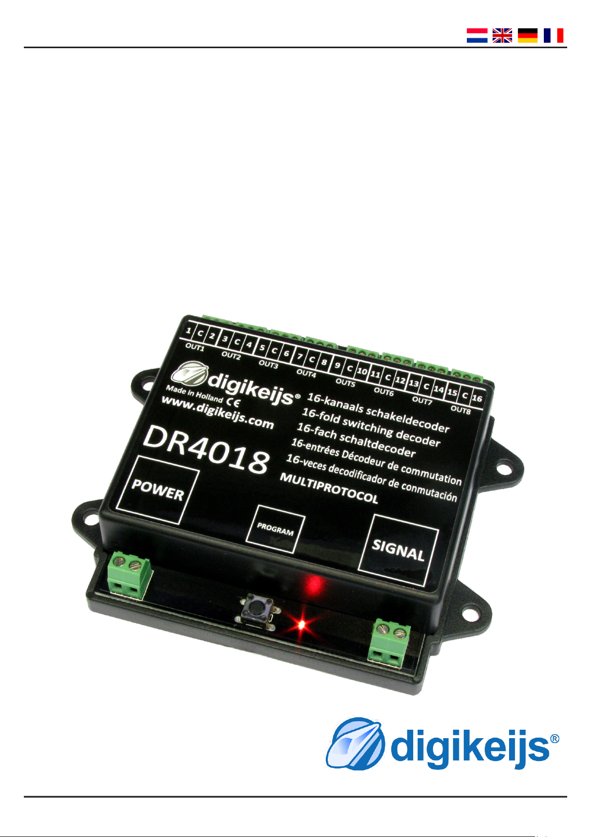
DR4018
DIGISWITCH
HANDLEIDING / MANUAL
BEDIENUNGSANLEITUNG / MANUEL
V1.34 (2015-05)
© Copyright 2005 – 2015 digikeijs, the Netherlands. All
rights re-served. No information, images or any part of
this document may be copied without the prior written
permission of Digikeijs.
www.digikeijs.com Pagina / page / Seite / page 1
Page 2

DR4018 DIGISWITCH (v1.34)
INDEX
Nederlandse Handleiding
Pagina 4 - Beschrijving van het product
Pagina 5 - Simpele start
Pagina 6 - CV / POM Programmeren
Pagina 7 - CV Lijst
Pagina 10 - Funcemappen
Pagina 11 - Geavanceerde instellingen
English manual
Page 11 - Product descripon
Page 12 - Quick start
Page 13 - CV / POM Programming
Page 14 - CV list
Page 16 - Funconmapping
Page 17 - Advanced sengs
Bedienungsanleitung Deutsch
Seite 18 - Produktbeschreibung
Seite 19 - Schnellstart
Seite 20 - CV / POM Programmierung
Seite 21 - CV Liste
Seite 23 - Funkonsmapping
Seite 24 - erweiterten Einstellungen
Manuel français
page 25 - Descripon du produit
page 26 - Démarrage rapide
page 27 - CV’s / POM programmaon
page 28 - Liste des CV’s
page 30 - Foncon de mappage
page 31 - paramètres avancés
www.digikeijs.com Pagina / page / Seite / page 2
Page 3

DR4018 DIGISWITCH (v1.34)
INDEX
Specieke Centrale instruces
Pagina 34 - Roco Z21 / Beginadres programmeren
Pagina 35 - Roco Z21 / Instellingen programmeren (POM)
Pagina 36 - Roco Mulmaus / Beginadres programmeren
Pagina 37 - Roco Mulmaus / Instellingen programmeren (POM)
Pagina 39 - Intellibox / Beginadres programmeren
Pagina 40 - Intellibox / Instellingen programmeren (POM)
Pagina 42 - LENZ LZV100 / Beginadres programmeren
Pagina 43 - LENZ LZV100 / Instellingen programmeren (POM)
Binnenkort:
Pagina 00 - Marklin CS2 / Beginadres programmeren
Pagina 00 - Marklin CS2 / Instellingen programmeren (POM)
Pagina 00 - Meedere presets tegelijk programmeren
www.digikeijs.com Pagina / page / Seite / page 3
Page 4
DR4018 DIGISWITCH (v1.34)
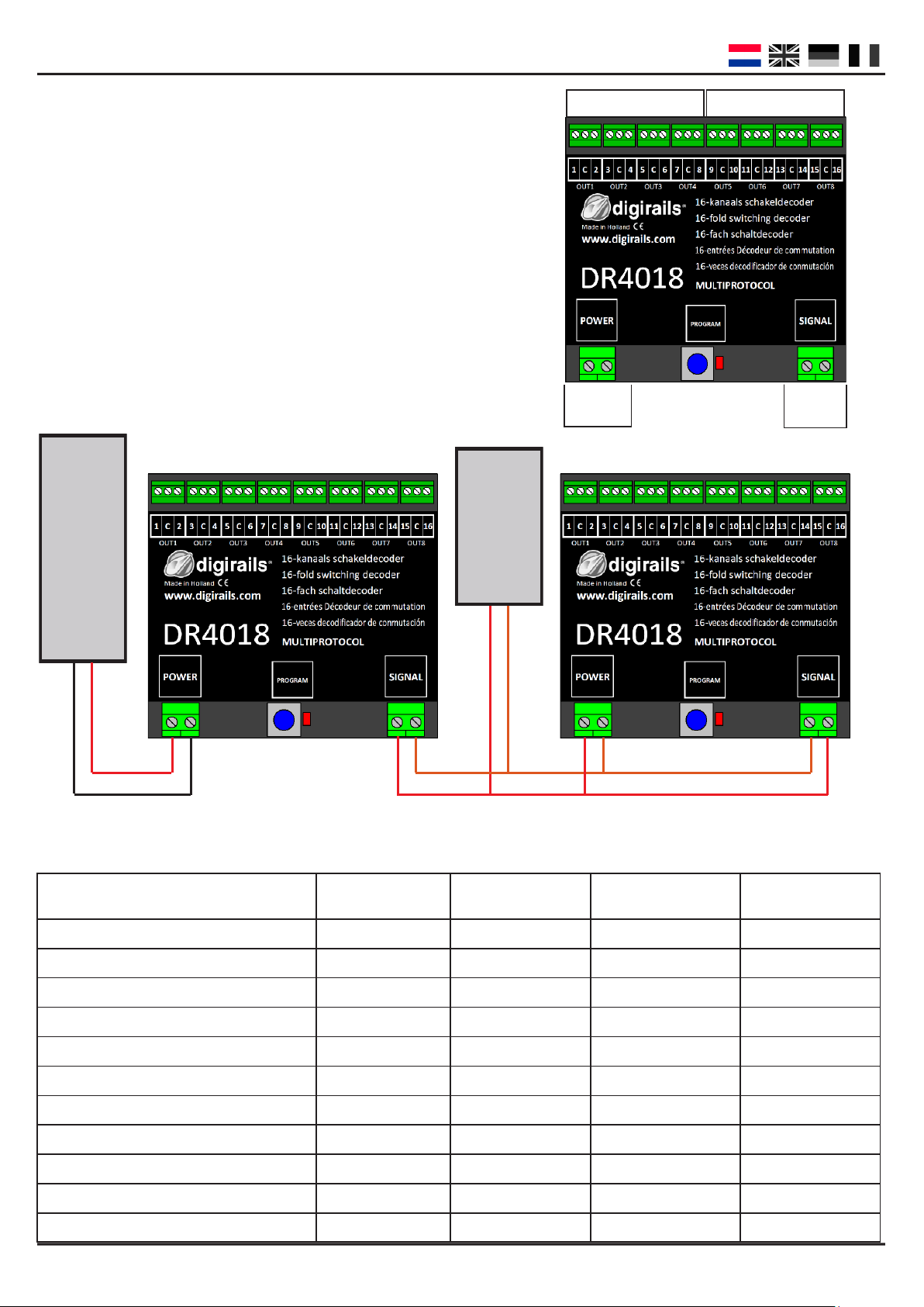
GROEP A GROEP B
Beschrijving van het product
De DIGISWITCH schakeldecoder is een volledig programmeerbaar, mulprotocol schakeldecoder waarmee u al
het denkbare op uw modelspoorbaan digitaal kunt schakelen. De schakeldecoder beschikt over 16 schakelbare
uitgangen waarmee u bijvoorbeeld 16 lampen of 8 wissels kunt schakelen. Tevens beschikt de schakeldecoder
over meerdere presets waarmee u 4 Nederlandse drie-
licht seinen met cijferbak, maar ook Belgische en Duitse
seinbeelden kunt schakelen.
12 - 18
Volt AC/DC
Centrale
EXTERNE VOEDING VOEDING DOOR CENTRALE
UNIT
AC of DC
CENTRALE
EXTERNE VOEDING
Compabiliteit met verschillende centrales
Omdat geen enkele centrale hetzelfde is kunt u via onderstaande tabel controleren welke mogelijkheden u
hee met uw centrale
Type Centrale Protocol Schakelen Programmeren via
programmeerspoor
POM
Intellibox DCC / Motorola V V V
Intellibox Basic DCC / Motorola V V V
Intellibox II DCC / Motorola V V V
Marklin 6021 Motorola V X X
Marklin CS1 / CS2 Motorola V V V
ROCO/Fleischmann Multimaus DCC V X V
ROCO/Fleischmann MultimausPRO DCC V V V
LENZ DCC V V V
Tams Easy control DCC / Motorola V V V
ESU ECOS DCC / Motorola V V V
Z21 DCC / Motorola V V V
www.digikeijs.com Pagina / page / Seite / page 4
Page 5

DR4018 DIGISWITCH (v1.34)
Snelle simpele start
Doormiddel van onderstaande stappen kunt u direct aan de slag met de decoder als 8 Kanaals wisseldecoder.
De module een adres geven
Om te beginnen hee de DR4018 module een adres nodig om te kunnen communiceren met uw centrale. Standaard wordt de module geleverd op adres “1” en is de module ingesteld als wisseldecoder en in DCC formaat.
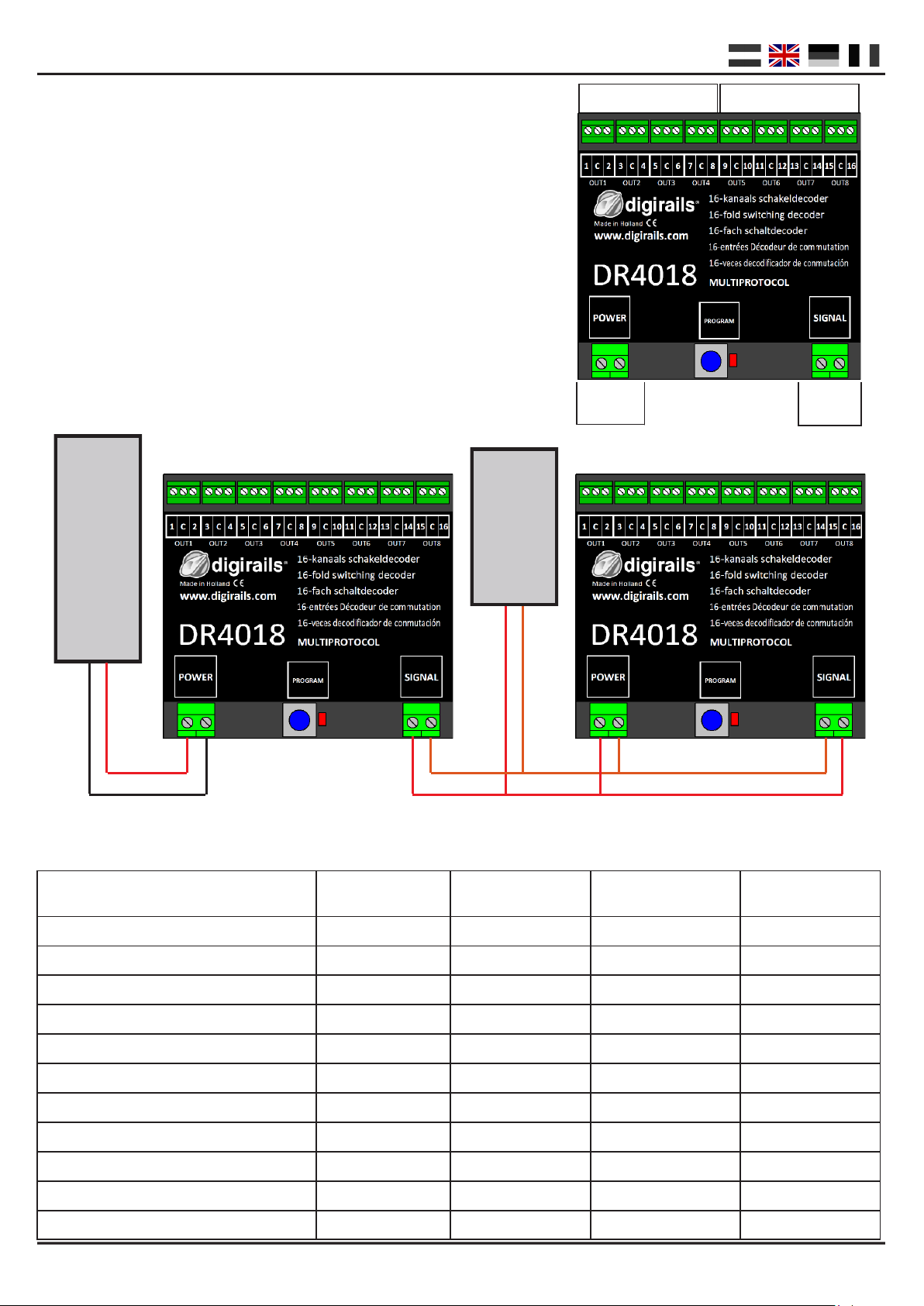
Stap 1 : Sluit zowel de POWER + SIGNAL tegelijk aan op de rails of rails (track) uitgang van uw centrale.
Stap 2 : Stel uw centrale in op het begin adres dat u de module wilt geven.
Stap 3 : Druk de programmeer schakelaar op de module in totdat de rode led blij branden.
Stap 4 : Schakel nu op uw centrale het ingestelde adres.
Stap 5 : Als de module correct is aangesloten doo de led nadat u het gewenste adres hee geschakeld
Stap 6 : De eerste uitgang (OUT1) hee nu het door u gekozen adres gekregen. Alle volgende OUT uit
gangen worden standaard voorzien van 1 nummer hoger.
Voorbeeld: U programmeert de module op adres 56 waarbij OUT1 adres 56 hee gekregen,
OUT2 nummer 57 krijgt, OUT3 nummer 58 etc etc…..
Omdat de decoder mulprotocol is en DCC en Marklin Motorola ondersteund, zal het kiezen van een wisseladres
ook het protocol selecteren. Tijdens het ontvangen van het wisselcommando zoals we in bovenstaande volgorde
hebben gedaan kijkt de decoder welk protocol gebruikt wordt en slaat dit op in zijn geheugen.
BELANGRIJK!
In DCC modus kunt u ieder willekeurig beginadres nummer kiezen waarbij de module automasch de opvolgende
uitgangen op 1 ophoogt.
Het Motorola protocol werkt met groepen van 8 nummers. U kunt hierbij geen tussenadres kiezen als
beginadres. Voorbeeld: adres 1 t/m 8 of 9 t/m 16 of 17 t/m 24 etc.
De module terug naar fabriekswaarden doormiddel van POM programmering
Doormiddel van onderstaande methode zet u de module terug naar fabriekswaarden via POM programmering.
Stap 1 : Sluit de signal ingang van de decoder aan op de rails uitgang van uw centrale.
Stap 2 : Zorg ervoor dat de module spanning krijgt via de power ingang van de module.
(U kunt ook de power en signal ingang met elkaar doorverbinden)
Stap 3 : Zet uw centrale in POM programmeer stand
(meer informae over POM staat in de handleiding van uw centrale)
Stap 5 : Kies locadres 9999 op uw centrale
Stap 6 : Druk op de schakelaar van de module totdat de led gaat branden
Stap 7 : Programmeer vervolgens decimaal waarde 8 in CV8
Stap 8 : Druk op de schakelaar van de module totdat de led doo
Stap 9 : Belangrijk bij een RESET is dat de module nu even zonder spanning komt te staan.
Dus koppel de decoder op zowel de power als de signal ingang los en wacht 3 tot 5 seconden.
Stap 10: De decoder kan terug onder spanning gezet worden en staat nu weer in de fabriekswaarden.
LET OP! De decoder hee vanaf nu ook weer adres 1
www.digikeijs.com Pagina / page / Seite / page 5
Page 6
DR4018 DIGISWITCH (v1.34)
Instellingen wijzigen van de decoder
Het wijzigen van instellingen zoals schakeljd of het kiezen van één van de vele presets in CV47 kan op
2 verschillende manieren die hieronder worden beschreven.
(1) CV Programmering / Uitlezing via programmeerspoor
Deze manier van programmeren is een veel gebruikte manier die vrij ingewikkeld kan zijn.
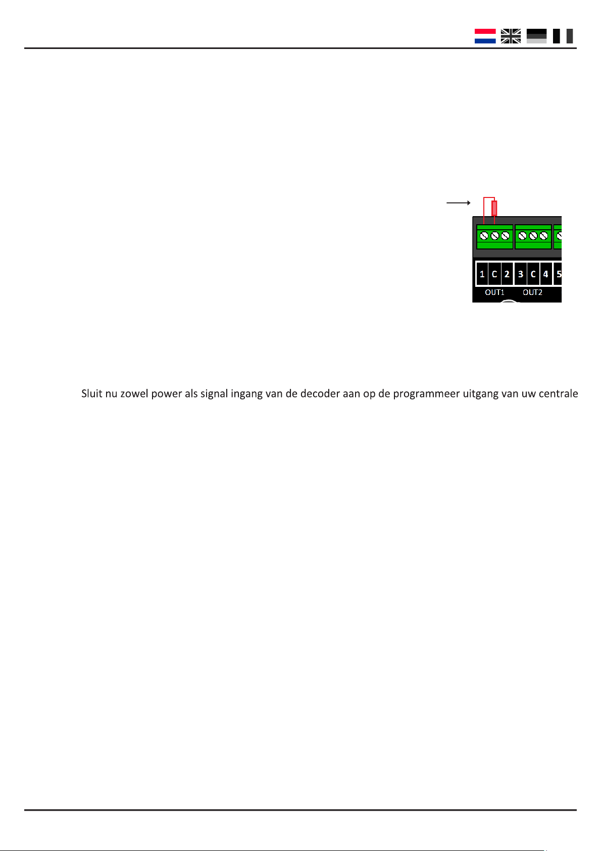
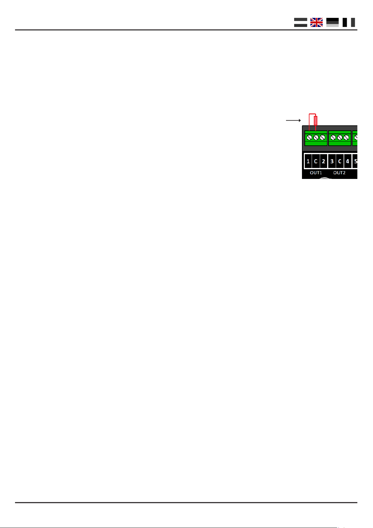
Om te beginnen moeten eerst de decoder voorbereiden doormiddel van het plaatsen van een belasngsweerstand van 150 of 270 Ohm op uitgang 1 zoals in de volgende aeelding geïllustreerd.
De weerstand zorgt ervoor dat er een belasng op het programmeerspoor ontstaat
die uw centrale nodig hee als bevesging dat er een module aanwezig is en ook
daadwerkelijk de programmeeropdracht van uw centrale hee ontvangen.
Helaas is geen centrale hetzelfde en kan het zijn dat de gemonteerde weerstand niet
voldoende of juist teveel belasng creëert. In dat geval dient u de handleiding van uw
centrale te raadplegen om de grote van de benodigde belasng te bepalen. In de meeste
gevallen kan het gebruik van een gloeilampje (12Volt - 60mA) de oplossing zijn.
Stap 1 : Sluit zowel power als signal ingang van de decoder aan op de rails uitgang van uw centrale.
Stap 2 : Druk de programmeer schakelaar op de module in totdat de rode led blij branden.
Stap 3 :
Stap 4 : Nu kunt u de gewenste CV’s wijzigen doormiddel van CV-byte of CV-bit programmering.
(Voor informae over CV-byte of CV-bit programmering raadpleegt u de handleiding van uw centrale)
Stap 5 : Sluit zowel power als signal ingang van de decoder aan op de rails uitgang van uw centrale.
Stap 6 : Druk de programmeer schakelaar op de module in totdat de led doo.
Stap 7 : Uw wijzigingen zijn opgeslagen en de module is klaar voor gebruik.
(2) CV Programmering via het hoofdspoor ( POM )
Een andere manier van programmeren is POM (Program On Main). Bij deze manier van programmeren kunt u de
module gewoon op de baan aansluiten zonder moeizame aansluingen of plaatsen van weerstanden zoals bij programmeren via het aparte programmeerspoor.
Stap 1 : Sluit de signal ingang van de decoder aan op de rails uitgang van uw centrale.
Stap 2 : Zorg ervoor dat de module spanning krijgt via de power ingang van de module.
(U kunt ook de power en signal ingang met elkaar doorverbinden)
Stap 3 : Zet uw centrale in POM programmeer stand
(meer informae over POM staat in de handleiding van uw centrale)
Stap 5 : Kies locadres 9999 op uw centrale
Stap 6 : Druk op de schakelaar van de module totdat de led gaat branden
Stap 7 : Programmeer vervolgens de gewenste CV’s van de module
Stap 8 : Druk op de schakelaar van de module totdat de led doo
Stap 9 : De module is direct klaar voor gebruik met de door u gewijzigde instellingen.
LET OP!!! In sommige gevallen kan het nodig zijn dat u de DR4018 module opnieuw een adres moet geven
doormiddel van ‘de module een adres geven’ op pagina 3 van deze handleiding.
www.digikeijs.com Pagina / page / Seite / page 6
Page 7
DR4018 DIGISWITCH (v1.34)
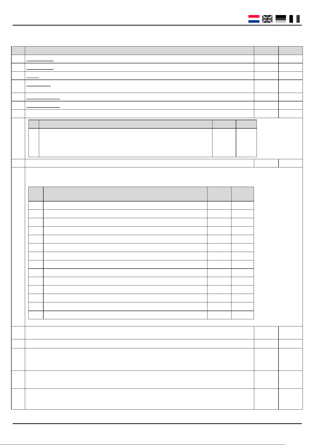
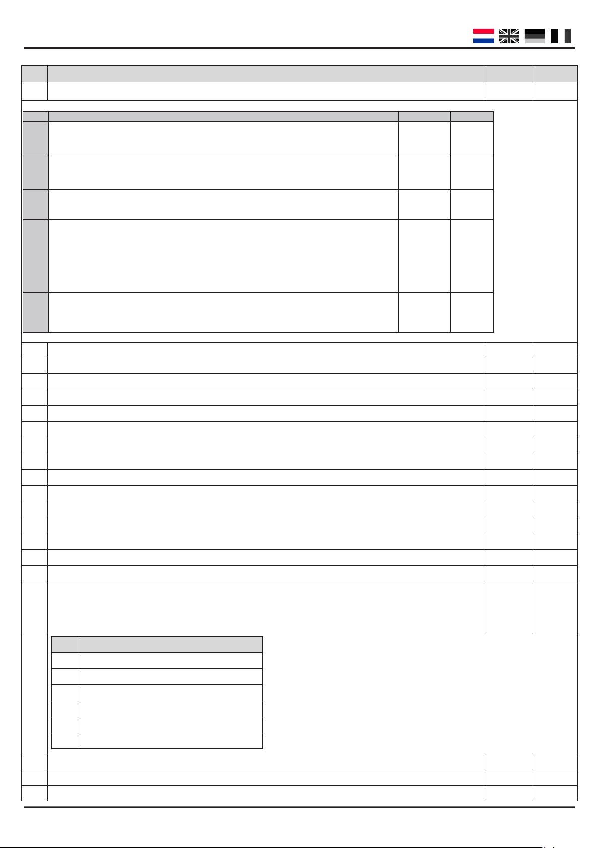
CV Lijst
#
CV Definities Bereik Waarde
513
Primair adres laag
521
Primair adres hoog
7
Versie van de decoder
8
Fabrikant-id waard e “ 8” leidt ertoe dat de fabriek si nstellingen word en i ngesteld .
1-127 4
1-127 0
- 134
- 42
17
Uitgebreid adres hog e byte
18
Uitgebreid adres lage b yte
29
Configuratie gegevens
Bit Funce Standaard Waarde
“0” = een byte adressering ( adres in CV513), “1” = twee byte addressering (Ook wel bekend als
5
uitgebreid adres in CV17 and CV18)
47
Voorinstellingen (CV113 t/m CV128) Alleen schrijfbaar
BELANGRIJK! : Deze CV is ni et uitlees baar om dat de wegg eschr even waarde niet opgesl agen word t m aar de co mplete
decoder configureert naar de gekozen preset instelling.
Preset Funces Waarde
0 8x Wissel met spoelaandrijving 0 8
1 16x permanent aan/uit schakelaar 1 16
2 8x Tweelichtsein met fader eect 2 8
3 8x AHOB 3 8
4 2 groepen van 8x TL verlichng eect 4 2
5 1 x 16 uitgangen met TL verl. Eect 5 1
6 8x Wisselmotor aansturing 6 8
7 4x NS drielichtsein met cijferbak 7 16
8 4x DB Hoofdsein 8 16
9 4x DB Voorsein behorend bij hoofdsein 9 16
10 2x Combinae DB hoofdsein en DB voorsein 10 8
11 4x DB Voorsein 11 16
12 4x NMBS Sein 12 16
13 8x Wisselmotor aansturing met jdsbegrenzing 13 8
“0” 32
Aantal
adressen
192-255 231
0-255 15
98
0 – 13 n/a
107 Donkertijd tussen de verschillende seinbeeld overgangen (duitse seinbeeld) 1-255 70
108 Waarde voor het dimmen van de seinen (nachtstand) 0-15 10
PWM-periode (pul sb reedte modulatie) De resolu ti e di e do or de int ern e PWM wo rd t gehanteerd voor het verwe-
109
zenlijken van effecten en dim-waarden
111
Fade-snelheid De snel heid waarm ee de uitgangen die voor de fade-functie zijn geconfigureerd, infaden en uitfaden
112
Knippersnelheid De snelheid waarmee de uitgangen knipperen die voor knipperen zijn geconfigureerd
1-255 14
1-255 3
1-255 183
www.digikeijs.com Pagina / page / Seite / page 7
Page 8
DR4018 DIGISWITCH (v1.34)
#
CV Definities Bereik Waarde
Uitgangsconfiguratie 1
113
0-255 143
Bit Function
Licht intensiteit / dimmer. Waarde 0 is complete gedimd. Waarde 15 is maximale lichtsterkte.
0 - 3
Fade in and Fade out effect. Waarde 0 is ui t. Waarde 1 is aan. Fade snel heid i s regelbaar in
CV111.
4
Knipper effect. Waarde 0 i s u it. Waard e 1 is aan. Kni pp er s nel heid is regelbaar in CV112
5
Willekeurig opstarten van de lampen. Waard e 0 is uit. Waarde 1 is aan. Opstart snelhei d i s
regelbaar in CV111.Gecombineerd met bit 4 (fade) start het licht met een flits op waarna ze langzaam opkomen. (gaslamp effect) Belangrijk: De licht intensiteit waard (bit 0-3) mag maximaal 14
6
zijn.
Pulse tijd Wordt ingesteld d oor CV238 t/m 253 waarde128, Gecom bineerd met bit 5 knippert de uitgang in tegengestelde fase.
7
Uitgangsconfiguratie 2 (Voor configuratie zie CV113)
114
Uitgangsconfiguratie 3 (Voor configuratie zie CV113)
115
Uitgangsconfiguratie 4 (Voor configuratie zie CV113)
116
Uitgangsconfiguratie 5 (Voor configuratie zie CV113)
117
Uitgangsconfiguratie 6 (Voor configuratie zie CV113)
118
Uitgangsconfiguratie 7 (Voor configuratie zie CV113)
119
Uitgangsconfiguratie 8 (Voor configuratie zie CV113)
120
Uitgangsconfiguratie 9 (Voor configuratie zie CV113)
121
Uitgangsconfiguratie 10 (Voor configuratie zie CV113)
122
Uitgangsconfiguratie 11 (Voor configuratie zie CV113)
123
Uitgangsconfiguratie 12 (Voor configuratie zie CV113)
124
Uitgangsconfiguratie 13 (Voor configuratie zie CV113)
125
Uitgangsconfiguratie 14 (Voor configuratie zie CV113)
126
Uitgangsconfiguratie 15 (Voor configuratie zie CV113)
127
Uitgangsconfiguratie 16 (Voor configuratie zie CV113)
128
Sein 1, configuratie OUT1 t/m 4
131
Als deze CV’s een waarde ongelijk aan 0 bevatten schakelen de betreffende uitgangen volgens de seinregels. De andere CV’s die normaal de uitgangen besturen staan buiten werking
Standaard
15
0
0
0 64
0
Waarde
0-15
16
32
128
0-255 143
0-255 143
0-255 143
0-255 143
0-255 143
0-255 143
0-255 143
0-255 143
0-255 143
0-255 143
0-255 143
0-255 143
0-255 143
0-255 143
0-255 143
0-5 0
Preset Funces
0 Geen sein
1 NS (Nederlands)
2 DB_HP (Duits hoofdsein)
3 DB_VRHP (Duits voor en hoofdsein)
4 DB_VR (Duits voorsein)
5 NMBS (Belgisch)
Sein 2, configuratie OUT 5 t/m 8
132
Sein 3, configuratie OUT 9 t/m 12
133
Sein 4, configuratie OUT 13 t/m 16
134
0-5 0
0-5 0
0-5 0
www.digikeijs.com Pagina / page / Seite / page 8
Page 9
DR4018 DIGISWITCH (v1.34)
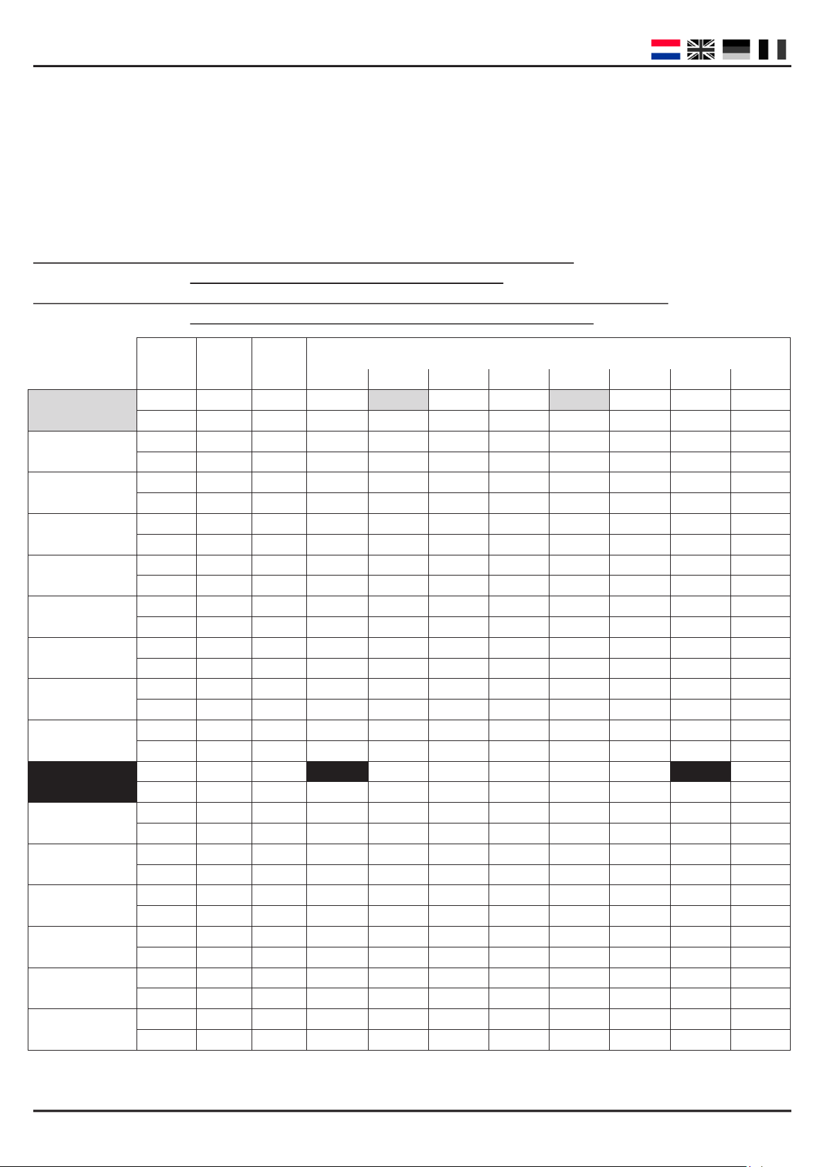
Funcemappen uitgang 1 t/m 16
Via onderstaande tabel kunt u de verschillende uitgangen van de DR4018 module (1 t/m 16) koppelen aan de
schakeltoetsen op uw centrale. Dit kan handig zijn op het moment dat u met 1 toets meerdere uitgangen tegelijk zou willen schakelen. In het geval dat u meerdere uitgangen wilt schakelen op 1 funcetoets in dezelfde
groep telt u de waarden bij elkaar op.
Voorbeeld (grijs): Toets 1 moet uitgang 2 en 5 schakelen jdens de AAN stand.
U programmeert in CV141 waarde 2 + 16 = 18
Voorbeeld 2 (zwart): Toets 10 moet uitgang 1 en uitgang 15 schakelen jdens de AAN stand.
U programmeert in CV195 waarde 1 en in CV196 waarde 64
Toets 1
Toets 2
Toets 3
Toets 4
Toets 5
Toets 6
Toets 7
Toets 8
Toets 9
Toets 10
Toets 11
Toets 12
Toets 13
Toets 14
Toets 15
Toets 16
Stand
CV
(A)
CV
(B)
AAN 141 1 2 4 8 16 32 64 128 142
UIT 144 1 2 4 8 16 32 64 128 145
AAN 147 1 2 4 8 16 32 64 128 148
UIT 150 1 2 4 8 16 32 64 128 151
AAN 153 1 2 4 8 16 32 64 128 154
UIT 156 1 2 4 8 16 32 64 128 157
AAN 159 1 2 4 8 16 32 64 128 160
UIT 162 1 2 4 8 16 23 64 128 163
AAN 165 1 2 4 8 16 32 64 128 166
UIT 168 1 2 4 8 16 32 64 128 169
AAN 171 1 2 4 8 16 32 64 128 172
UIT 174 1 2 4 8 16 32 64 128 175
AAN 177 1 2 4 8 16 32 64 128 178
UIT 180 1 2 4 8 16 32 64 128 181
AAN 183 1 2 4 8 16 32 64 128 184
UIT 186 1 2 4 8 16 32 64 128 187
AAN 189 1 2 4 8 16 32 64 128 190
UIT 192 1 2 4 8 16 32 64 128 193
AAN 195 1 2 4 8 16 32 64 128 196
UIT 198 1 2 4 8 16 32 64 128 199
AAN 201 1 2 4 8 16 32 64 128 202
UIT 204 1 2 4 8 16 32 64 128 205
AAN 207 1 2 4 8 16 32 64 128 208
UIT 210 1 2 4 8 16 32 64 128 211
AAN 213 1 2 4 8 16 32 64 128 214
UIT 216 1 2 4 8 16 32 64 128 217
AAN 219 1 2 4 8 16 32 64 128 220
UIT 222 1 2 4 8 16 32 64 128 223
AAN 225 1 2 4 8 16 32 64 128 226
UIT 228 1 2 4 8 16 32 64 128 229
AAN 231 1 2 4 8 16 32 64 128 232
UIT 234 1 2 4 8 16 32 64 128 235
UITGANGEN GROEP A ( 1 t/m 8 ) en GROEP B ( 9 t/m 16 )
1 | 9 2 | 10 3 | 11 4 | 12 5 | 13 6 | 14 7 | 15 8 | 16
* De ROOD gekleurde getallen zijn de standaard fabriekswaarden voor GROEP A ( 1 t/m 8 )
* De ORANJE gekleurde getallen zijn de standaard fabriekswaarden voor GROEP B ( 9 t/m 16 )
www.digikeijs.com Pagina / page / Seite / page 9
Page 10
DR4018 DIGISWITCH (v1.34)
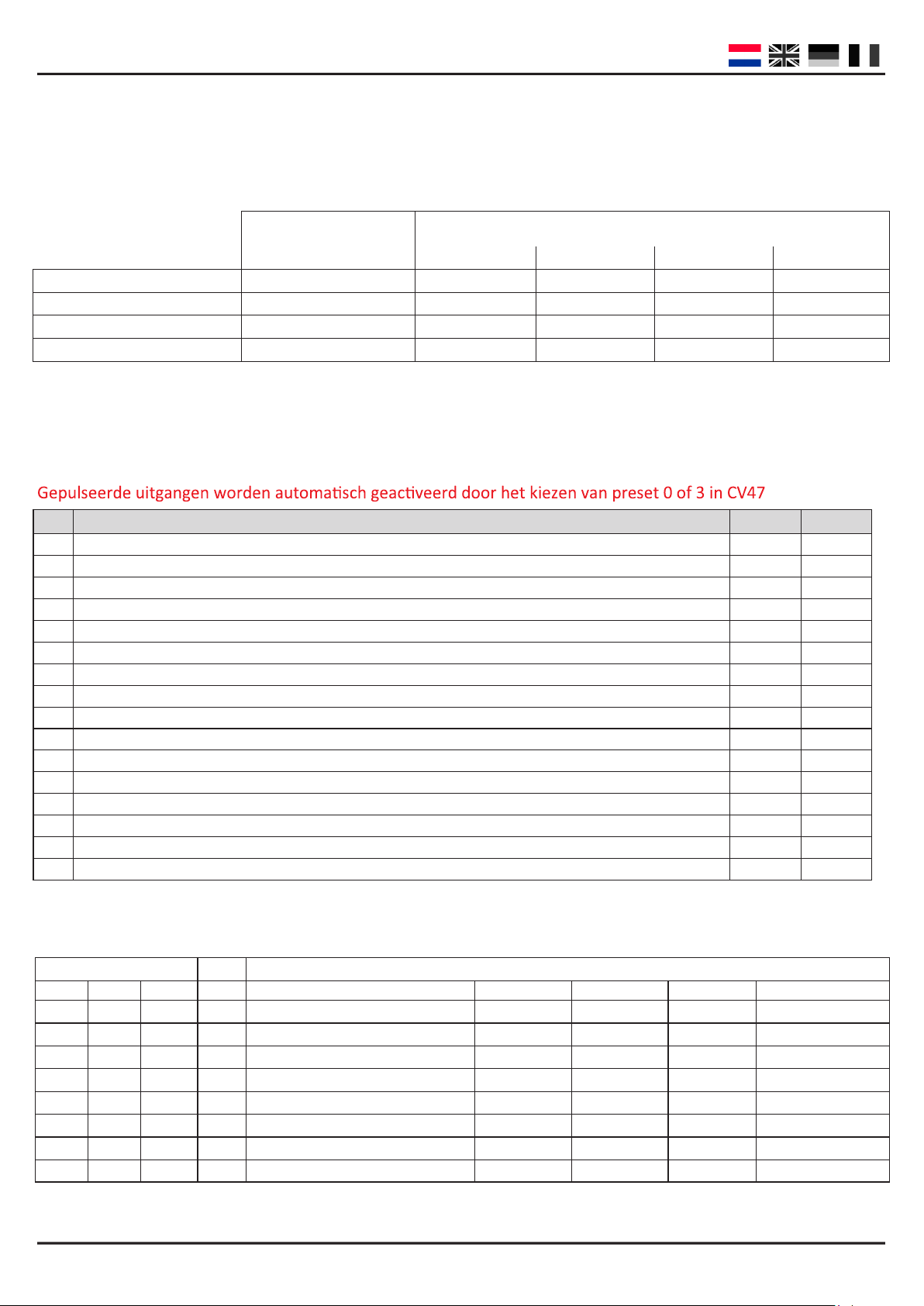
Sein funcemappen uitgang (EXPERT)
Via onderstaande tabel zijn de verschillende sein nummers gekoppeld aan uitgangsgroepen. Het wijzigen van
deze congurae kan handig zijn op het moment dat u zowel seinen als wissels gecombineerd gaat aanstruren
met dezelfde module.
UITGANGEN
CV
1 –4 5—8 9-12 13-16
SEIN 1 143 1 2 4 8
SEIN 2 167 1 2 4 8
SEIN 3 191 1 2 4 8
SEIN 4 215 1 2 4 8
Uitgang pulsjden
Met onderstaande CV’s kunt u de pulsduur van de uitgangen 1 t/m 16instellen mits deze op puls ingesteld staat
CV113=7 en CV47=13.
CV
CV Definities Range Value
238 Pulsduur UITGANG 1 0-255 128
239 Pulsduur UITGANG 2 0-255 128
240 Pulsduur UITGANG 3 0-255 128
241 Pulsduur UITGANG 4 0-255 128
242 Pulsduur UITGANG 5 0-255 128
243 Pulsduur UITGANG 6 0-255 128
244 Pulsduur UITGANG 7 0-255 128
245 Pulsduur UITGANG 8 0-255 128
246 Pulsduur UITGANG 9 0-255 128
247 Pulsduur UITGANG 10 0-255 128
248 Pulsduur UITGANG 11 0-255 128
249 Pulsduur UITGANG 12 0-255 128
250 Pulsduur UITGANG 13 0-255 128
251 Pulsduur UITGANG 14 0-255 128
252 Pulsduur UITGANG 15 0-255 128
253 Pulsduur UITGANG 16 0-255 128
Seinbeelden
De combinatie van de drie eerste adressen bepaalt 1 van de 8 mogelijke seinbeelden. Het 4e adres schakelt de (nacht)
dimstand in.
Adres Seinbeeld
e
1
R R R 0 Rood HP0 Gedoofd VR0 Rood
G R R 1 Groen HP1 VR0 VR1 Rood knipper
R G R 2 Geel HP2 VR0 VR2 Dubbel Geel
G G R 3 Groen-knipper met Cijfer SH1 Gedoofd Gedoofd Dubbel Geel knipper
R R G 4 Geel met Cijfer HP1 VR1 VR0 Groen Geel Horizont.
G R G 5 Groen-knipper HP2 VR1 VR1 Groen
R G G 6 Geel-knipper HP1 VR2 VR2 Groen knipper
G G G 7 Geel met Cijfer-knipper HP2 VR2 Gedoofd Groen Geel Verticaal
R = Rode knop op uw centrale
G = Groene knop op uw centrale
www.digikeijs.com Pagina / page / Seite / page 10
e
2
e
3
NS 3-lichts met cijferbak DB HP DB VR-Combi DB VR NMBS
Page 11
DR4018 DIGISWITCH (v1.34)
GROUP A GROUP B
Product descripon
The DIGISWITCH switching decoder is a fully programmable, mul-protocol switching decoder that can digitally
switch anything imaginable on your model railway. The
switching decoder has 16 switchable outlets which can,
for example, switch 16 lights or 8 sets of points. The
switching decoder has several presets that enable you to
switch four Dutch three-light signals with number
boards. Belgian and German signal aspects can also be
switched.
12 - 18
Volt AC/DC
Central
EXTERNAL FEED FEED FROM CONTROL UNIT
UNIT
CONTROL
AC or DC
EXTERNAL FEED
Compability with dierent control units
Because no two control units are the same, use the table below to see what opons you have with your unit.
Control unit type Protocol Switching Programming via
programming track
POM
Intellibox
Intellibox Basic
Intellibox II
Marklin 6021
Marklin CS1 / CS2
ROCO/Fleischmann Multimaus
ROCO/Fleischmann MultimausPRO
LENZ
Tams Easy control
ESU ECOS
Z21
DCC / Motorola
DCC / Motorola
DCC / Motorola
Motorola
Motorola
DCC
DCC
DCC
DCC / Motorola
DCC / Motorola
DCC / Motorola
V V V
V V V
V V V
V X X
V V V
V X V
V V V
V V V
V V V
V V V
V V V
www.digikeijs.com Pagina / page / Seite / page 11
Page 12

DR4018 DIGISWITCH (v1.34)
Quick start
Follow these steps to start using your decoder as an 8-channel switching decoder straight away.
Give the module an address
The DR4018 module rst needs an address to be able to communicate with your control unit.
The module comes as standard with address “1” and set up as a switching decoder using DCC format.
Step 1 : Connect both the POWER + SIGNAL to the rails or tracks output on your control unit.
Step 2 : Set your control unit to the starng address you want to give the module.
Step 3 : Press the program buon on the module unl the red LED remains on.
Step 4 : Now switch your control unit to the selected address.
Step 5 : If the module is connected correctly, the LED will go o when you select the address.
Step 6 : The rst output (OUT1) has now received the selected address. All subsequent OUT outputs are
given an address 1 number higher.
Example: The module is programmed to address 56. OUT1 is given the address 56, OUT2 gets
address 57, OUT3 number 58 etc.
Because the decoder is mulprotocol and supports DCC and Marklin Motorola, selecng a switching address
should also select the protocol. When the decoder receives a switching command as per the steps above, the decoder idenes which protocol was used and stores this in its memory.
IMPORTANT!
In DCC mode you can select any starng address and the module will automacally give the subsequent outputs
an address that is one higher.
The Motorola protocol works with groups of 8 numbers. This means you cannot chose a starng address from
within a block. For example: address 1 through 8, 9 through 16, 17 through 24 etc.
Reset the module to factory sengs using POM programming
Use this method to reset the module to factory sengs using POM programming.
Step 1 : Connect the signal input on the decoder to the rails output on your control unit.
Step 2 : Ensure the module is receiving power via the module’s power input.
(You can also connect the power and signal inputs to each other)
Step 3 : Set your control unit to POM programming mode.
(You can nd more informaon about the POM mode in your control unit’s manual)
Step 5 : Choose local address 9999 on your control unit.
Step 6 : Press the buon on the module unl the LED goes on.
Step 7 : Then program decimal value 8 in CV8.
Step 8 : Press the buon on the module unl the LED goes out.
Step 9 : It is important when carrying out a RESET that the module is now disconnected from the power.
Disconnect both the power and the signal inputs and wait for 3 to 5 seconds.
Step 10: The decoder can now be reconnected to the power and will have returned to the factory sengs.
BE CAREFUL! The decoder now has address 1 again.
www.digikeijs.com Pagina / page / Seite / page 12
Page 13
DR4018 DIGISWITCH (v1.34)
Modify the decoder’s sengs
There are two ways of changing the decoder’s sengs and/or switching me, or chosing one of the many presets
in CV47. They are described below.
(1) CV Programming / reading through the programming track
This common way of programming can become rather complicated.
The decoder must rst be prepared by placing a 150—270 Ohm resistor on output 1 as shown in the diagram.
The resistor ensures that there is a resistance on the programming track, which your
control unit requires as conrmaon that a module is present and that the
programming commands have been received from the control unit.
Unfortunately, no two control units are the same and it is possible that the aached resistor
does not provide enough, or provides too much, resistance. If this happens,
consult your control unit’s manual to nd out what resistance is required. In most cases
using a bulb (12 Volt—60 mA) works well.
Step 1 : Connect both the power and signal inputs on the decoder to the rails output on your control unit.
Step 2 : Press the program buon on the module unl the red LED stays on.
Step 3 : Now connect both the power and signal input on the decoder to the program output on your control
unit.
Step 4 : You can now modify the CVs using CV byte or CV bit programming.
(For informaon about CV byte or CV bit programming, please consult your control unit’s manual)
Step 5 : Connect both the power and signal inputs on the decoder to the rails output on your control unit.
Step 6 : Press the program buon on the module unl the LED goes out.
Step 7 : Your modicaons have been saved and the module is ready for use.
(2) CV Programming via the main track (POM)
An alternave way of programming is POM (Program On Main). This method of programming allows you to connect the module directly to the track without the diculty of aaching a resistor, as is required when programming via a separate programming track.
Step 1 : Aach the signal input on the decoder to the rails output on your control unit.
Step 2 : Ensure the module is receiving power via the module’s power input.
(You can also connect the power and signal inputs to each other)
Step 3 : Set your control unit to POM programming mode.
(You can nd more informaon about the POM mode in your control unit’s manual)
Step 5 : Choose local address 9999 on your control unit.
Step 6 : Press the buon on the module unl the LED goes on.
Step 7 : Now program the desired CVs for the module.
Step 8 : Press the buon on the module unl the LED goes out.
Step 9 : The module is ready for immediate use with the modied sengs.
BE CAREFUL! In some cases the DR4018 must be given a new address by following the steps in the ‘Give the mo-
dule an address’ secon on page 3 of this manual.
www.digikeijs.com Pagina / page / Seite / page 13
Page 14
DR4018 DIGISWITCH (v1.34)
CV List
#
CV Definition Range Value
513
Primary Address Low
521
Primary Address High
7
Version of the decoder
8
Manufacturer ID Writing the value “8” will reset the decoder to it’s factory settings
1-127 4
1-127 0
- 134
- 42
17
Extended Address hig h b yte
18
Extended Address low byte
29
Configuration Data
Bit Funcon Default Value
“0” = one byte addressing ( address in
CV1), “1” = two byte addressing (also
5
known as extended addressing, address in CV17 and 18)
47
Presets (CV113 through CV128) WRITE ONLY
IMPORTANT! : Thi s CV i s not readable as entered values will not be st or ed, r ather t he enti re decoder will b e co nf ig ured
according to the preset selected..
Preset Funcon Value
0 8x Turnout with twin-coil motor 0 8
1 16x permanent on/o switch 1 16
2 8x two-light signal with fade eect 2 8
3 8x AHOB 3 8
4 2 groups with 8x Fluorescent lamp 4 2
5 1 x 16 output with Fluorescent lamp 5 1
6 8x Turnout motor control 6 8
7 4x Dutch three-light signal 7 16
8 4x DB Main signal 8 16
9 4x DB pre-signal associated with main signal 9 16
10 2x Combinaon of DB Main signal and pre-signal 10 8
11 4x DB Pre-signal 11 16
12 4x NMBS Main signal 12 16
13 8x Turnout control with me limit 13 8
“0” 32
No. of
addresses
192-255 231
128-255 15
98
0 – 13 n/a
107 Dark time between signal transitions 1-255 70
108 Value to dim intensity of signal (night mode) 0-15 10
109
PWM Period The res ol ution wi th wh ich the internal PWM operates to achieve effects and dim -values
111
Fade Speed The speed with which the outputs configured for fading will fade in and fade out
112
Blink rate The sp eed with which the outpu ts co nf igured for bli nkin g wil l blin k
1-255 14
1-255 3
1-255 183
www.digikeijs.com Pagina / page / Seite / page 14
Page 15

DR4018 DIGISWITCH (v1.34)
#
CV Definition Range Value
113
Output Configuration 1
0-255 143
Function Default
Bit
Intensity of the output. Also called d im mer. Where 0 is co mpletely
off and 15 completely on.
0 - 3
Fade in and fade out effect. "0" = n o fadi ng " 1" = fading act ive.
Fade speed is controlled by CV111
4
Blink effect. "0" = no blin king " 1" = bli nking active. Blin k r ate i s
controlled by CV112
5
Random effect. "0" = random off " 1" = random activ e. Combined
with bit 4 (fade) the lights start with a flash, after which they slowly fade
in. Note: The intensity value should be max. 14 for this effect to work.
6
Pulse length. is set via CV 121 thr ough 128, when c om bined with
bit 5 the output blinks, but with inverted phase
7
114 Output Configuration 2 (For configuration bits see CV113) 0-255 143
115 Output Configuration 3 (For configuration bits see CV113) 0-255 143
116 Output Configuration 4 (For configuration bits see CV113) 0-255 143
117 Output Configuration 5 (For configuration bits see CV113) 0-255 143
118 Output Configuration 6 (For configuration bits see CV113) 0-255 143
119 Output Configuration 7 (For configuration bits see CV113) 0-255 143
120 Output Configuration 8 (For configuration bits see CV113) 0-255 143
121 Output Configuration 9 (For configuration bits see CV113) 0-255 143
122 Output Configuration 10 (For configuration bits see CV113) 0-255 143
123 Output Configuration 11 (For configuration bits see CV113) 0-255 143
124 Output Configuration 12 (For configuration bits see CV113) 0-255 143
125 Output Configuration 13 (For configuration bits see CV113) 0-255 143
126 Output Configuration 14 (For configuration bits see CV113) 0-255 143
127 Output Configuration 15 (For configuration bits see CV113) 0-255 143
128 Output Configuration 16 (For configuration bits see CV113) 0-255 143
Signal 1, configuration OUT 1 - 4
131
If these CVs contain a value equal to 0 all outputs will switch according to the signal rules. The other CVs that normally control the outputs will be deactivated.
Value
15
0
0
0 64
0
0-15
128
16
32
0-5 0
Preset Funcon
0 No Signal
1 Dutch (railways)
2 DB_HP (German main signal)
3 DB_VRHP (German front and main signal)
4 DB_VR (German front signal)
5 NMBS (Belgium railways)
132 Signal 2, configuration OUT 5 - 8 0-5 0
133 Signal 3, configuration OUT 9 - 12 0-5 0
134 Signal 4, configuration OUT 13 - 16 0-5 0
www.digikeijs.com Pagina / page / Seite / page 15
Page 16

DR4018 DIGISWITCH (v1.34)
Funcon mapping outputs 1 through 16
This table shows you how to connect the dierent outputs on the DR4018 module (1 through 16) to the switching keys on your control unit. This is useful when you want to switch more than one output at the same me
with one key. If you want to switch more than one output with one funcon key in the same group then add the
values together.
Example 1 (grey): Key 1 should switch outputs 2 and 5 when ON.
You program: CV141 values 2 + 16 = 18.
Example 2 (black): Key 10 should switch ouputs 1 and 15 when ON.
You program: CV195 value 1 and CV196 value 64.
Key 1
Key 2
Key 3
Key 4
Key 5
Key 6
Key 7
Key 8
Key 9
Key 10
Key 11
Key 12
Key 13
Key 14
Key 15
Key 16
Status
ON 141 1 2 4 8 16 32 64 128 142
OFF 144 1 2 4 8 16 32 64 128 145
ON 147 1 2 4 8 16 32 64 128 148
OFF 150 1 2 4 8 16 32 64 128 151
ON 153 1 2 4 8 16 32 64 128 154
OFF 156 1 2 4 8 16 32 64 128 157
ON 159 1 2 4 8 16 32 64 128 160
OFF 162 1 2 4 8 16 23 64 128 163
ON 165 1 2 4 8 16 32 64 128 166
OFF 168 1 2 4 8 16 32 64 128 169
ON 171 1 2 4 8 16 32 64 128 172
OFF 174 1 2 4 8 16 32 64 128 175
ON 177 1 2 4 8 16 32 64 128 178
OFF 180 1 2 4 8 16 32 64 128 181
ON 183 1 2 4 8 16 32 64 128 184
OFF 186 1 2 4 8 16 32 64 128 187
ON 189 1 2 4 8 16 32 64 128 190
OFF 192 1 2 4 8 16 32 64 128 193
ON 195 1 2 4 8 16 32 64 128 196
OFF 198 1 2 4 8 16 32 64 128 199
ON 201 1 2 4 8 16 32 64 128 202
OFF 204 1 2 4 8 16 32 64 128 205
ON 207 1 2 4 8 16 32 64 128 208
OFF 210 1 2 4 8 16 32 64 128 211
ON 213 1 2 4 8 16 32 64 128 214
OFF 216 1 2 4 8 16 32 64 128 217
ON 219 1 2 4 8 16 32 64 128 220
OFF 222 1 2 4 8 16 32 64 128 223
ON 225 1 2 4 8 16 32 64 128 226
OFF 228 1 2 4 8 16 32 64 128 229
ON 231 1 2 4 8 16 32 64 128 232
OFF 234 1 2 4 8 16 32 64 128 235
CV
(A)
CV
(B)
OUTPUTS GROUP A ( 1 through 8 ) and GROUP B ( 9 through 16 )
1 | 9 2 | 10 3 | 11 4 | 12 5 | 13 6 | 14 7 | 15 8 | 16
* The RED numbers are the standard factory sengs for GROUP A (1 through 8)
* The ORANGE numbers are the standard factory sengs for GROUP B ( 9 through 16 )
www.digikeijs.com Pagina / page / Seite / page 16
Page 17

DR4018 DIGISWITCH (v1.34)
Signal funcon mapping output (EXPERT)
This table shows how the dierent signal numbers are coupled to output groups. It can be useful to change this
conguraon when you want to control both signals and points with the same module.
OUTPUTS
CV
1 –4 5—8 9-12 13-16
SIGNAL 1 143 1 2 4 8
SIGNAL 2 167 1 2 4 8
SIGNAL 3 191 1 2 4 8
SIGNAL 4 215 1 2 4 8
Output pulse mes
Use these CVs to congure the pulse duraon for outputs 1 through 16 provided they are set to pulse CV113=7
and CV47=13.
CV
CV Definition Range Value
238 Pulse time OUTPUT 1 0-255 128
239 Pulse time OUTPUT 2 0-255 128
240 Pulse time OUTPUT 3 0-255 128
241 Pulse time OUTPUT 4 0-255 128
242 Pulse time OUTPUT 5 0-255 128
243 Pulse time OUTPUT 6 0-255 128
244 Pulse time OUTPUT 7 0-255 128
245 Pulse time OUTPUT 8 0-255 128
246 Pulse time OUTPUT 9 0-255 128
247 Pulse time OUTPUT 10 0-255 128
248 Pulse time OUTPUT 11 0-255 128
249 Pulse time OUTPUT 12 0-255 128
250 Pulse time OUTPUT 13 0-255 128
251 Pulse time OUTPUT 14 0-255 128
252 Pulse time OUTPUT 15 0-255 128
253 Pulse time OUTPUT 16 0-255 128
Signal aspects
The combination of the first three addresses determines 1 of 8 possible signal aspects. The fourth address activates (night)
dimming.
1
R R R 0 Red HP0 Off VR0 Red
G R R 1 Green HP1 VR0 VR1 Flashing red
R G R 2 Yellow HP2 VR0 VR2 Double yellow
G G R 3 Flashing green with digit SH1 Off Off Flash double yellow
R R G 4 Yellow with digit HP1 VR1 VR0 Green yellow horiz.
G R G 5 Flashing green HP2 VR1 VR1 Green
R G G 6 Flashing yellow HP1 VR2 VR2 Flashing green
G G G 7 Yellow with flashing digit HP2 VR2 Off Green yellow vertical
R = Red button on your control unit
G = Green button on your control unit
www.digikeijs.com Pagina / page / Seite / page 17
Address Signal aspect
e
e
2
e
3
NS 3 lights with digit board
DB HP DB VR-Combi DB VR NMBS
Page 18

DR4018 DIGISWITCH (v1.34)
Produktbeschreibung
Der DIGISWITCH Schaltdecoder ist ein voll programmierbarer Mulprotokoll-Schaltdecoder, der auf digitale Weise alles, was Sie sich nur vorstellen können, auf
Ihrer Modelleisenbahn schalten kann. Der Schaltdecoder hat 16 verstellbare Ausgänge, die zum Beispiel zwischen 16 Lichtern oder 8 Weichen schalten können.
Der Schaltdecoder hat mehrere Einstellungen, mit denen man vier niederländische drei-Licht Signale mit di-
GRUPPE A GRUPPE B
gitaler Anzeigetafel betägen kann. Man kann damit
auch belgische oder deutsche Signalaspekte betägen.
12 - 18
Volt AC/DC
Zentral
EINSPEISUNG DURCH
EXTERNE EINSPEISUNG
-
KONTROLLEINHEIT
EINHEIT
KONTROLL
UNG AC oder DC
EXTERNE EINSPEIS-
Kompabilität mit verschiedenen Kontrolleinheiten
Kontrolleinheiten sind alle unterschiedlich. Mit Hilfe der folgenden Tabelle können Sie die Oponen für Ihre Einheit ermieln.
Kontrolleinheitstyp Protokoll Schaltung Programmierung durch
Programmiergleis
POM
Intellibox
Intellibox Basic
Intellibox II
Marklin 6021
Marklin CS1 / CS2
ROCO/Fleischmann Multimaus
ROCO/Fleischmann MultimausPRO
LENZ
Tams Easy control
ESU ECOS
Z21
DCC / Motorola
DCC / Motorola
DCC / Motorola
Motorola
Motorola
DCC
DCC
DCC
DCC / Motorola
DCC / Motorola
DCC / Motorola
V V V
V V V
V V V
V X X
V V V
V X V
V V V
V V V
V V V
V V V
V V V
www.digikeijs.com Pagina / page / Seite / page 18
Page 19

DR4018 DIGISWITCH (v1.34)
Schnellstart
Befolgen Sie diese Schrie, um Ihren Decoder sofort als 8-fachen Schaltdecoder zu verwenden.
Besmmen Sie eine Adresse für das Modul
Als erstes braucht das DR4018 Modul eine Adresse, um mit Ihrer Kontrolleinheit kommunizieren zu können.
Das Modul hat standardmäßig die Adresse “1” und ist als Wechseldecoder in DCC Format eingestellt.
Schri 1 : Verbinden Sie sowohl POWER + SIGNAL mit dem Schienenausgang Ihrer Kontrolleinheit.
Schri 2 : Stellen Sie die Kontrolleinheit auf die gewünschte Startadresse ein.
Schri 3 : Drücken Sie auf den Programmknopf des Moduls bis die rote LED Leuchte an bleibt.
Schri 4 : Schalten Sie die Kontrolleinheit nun auf die gewünschte Adresse.
Schri 5 : Bei richger Verbindung des Moduls, geht die LED Leuchte aus, sobald Sie eine Adresse wählen.
Schri 6 : Der erste Ausgang (OUT1) hat nun die ausgewählte Adresse erhalten. Alle weiteren Ausgänge
erhalten eine Adresse, die eine Nummer höher ist.
Beispiel: Das Modul ist mit der Adresse 56 programmiert. OUT1 erhält also die Adresse 56,
OUT2 erhält die Adresse 57, OUT3 Adresse 58 usw.
Weil der Decoder mulprotokoll ist und sowohl DCC als auch Marklin Motorola unterstützt, sollte bei der Wahl
einer Schaltadresse auch ein Protokoll ausgewählt werden. Wenn der Decoder nach den oben genannte Schrien
ein Schaltkommando enthält, ermielt der Decoder welches Protokoll gewählt wurde und speichert diese Einstellung.
WICHTIG!
Im DCC Modus können Sie eine beliebige Startadresse wählen und das Modul programmiert dann automasch
den folgenden Ausgang mit einer Adresse, die eine Nummer höher ist.
Das Motorola Protokoll funkoniert mit Gruppierungen von 8 Nummern. Dies bedeutet, dass Sie eine Adresse am
Anfang einer Gruppierung wählen müssen. Gruppierungen sind z.B.: Adressen 1 bis 8, 9 bis 16, 17 bis 24 etc.
Mit POM Programmierung auf Werkeinstellungen zurücksetzen
So können Sie das Modul mit Hilfe der POM Programmierung auf die Werkeinstellungen zurücksetzen.
Schri 1 : Verbinden Sie den Signaleingang des Decoders mit dem Gleisausgang der Kontrolleinheit.
Schri 2 : Stellen Sie sicher, dass das Modul über den Stromeingang mit Strom versorgt wird.
(Sie können die Strom– und Signaleingänge auch miteinander verbinden)
Schri 3 : Stellen Sie die Kontrolleinheit auf POM Programmierungsmodus ein.
(Weitere Informaonen zum POM Modus nden Sie im Handbuch Ihrer Kontrolleinheit)
Schri 5 : Wählen Sie die lokale Adresse 9999 auf Ihrer Kontrolleinheit aus.
Schri 6 : Drücken Sie auf den Knopf des Moduls, bis die LED Leuchte sich einschaltet.
Schri 7 : Programmieren Sie dann den Dezimalwert 8 in CV8 ein.
Schri 8 : Drücken Sie auf den Knopf des Moduls bis die LED Leuchte sich ausschaltet.
Schri 9 : Wenn Sie einen RESET durchführen, dann ist es wichg, dass das Modul an dieser Stelle von der
Stromversorgung getrennt wird. Trennen Sie den Strom– und den Signaleingang und warten Sie 3 bis
5 Sekunden.
Schri 10: Der Decoder kann nun wieder angeschlossen werden und wird auf den Werkzustand zurückgesetzt
worden sein.
ACHTUNG! Der Decoder hat nun wieder die Adresse 1.
www.digikeijs.com Pagina / page / Seite / page 19
Page 20

DR4018 DIGISWITCH (v1.34)
Änderungen der Decoder Einstellungen
Man kann auf zwei Weisen die Einstellungen und/oder Schaltzeiten des Decoders ändern, oder eine der vielen
Voreinstellungen in CV47 auswählen. Diese beiden Methoden werden hier beschrieben.
(1) CV Programmierung / Lesen am Programmiergleis
Diese geläuge Art der Programmierung kann ziemlich kompliziert werden.
Als erstes muss der Decoder vorbereitet werden, indem ein 150—270 Ohm Widerstand an den Ausgang 1 angeschlossen wird, wie im Diagramm gezeigt.
Der Widerstand sorgt dafür, dass es einen Widerstand am Programmiergleis gibt.
Dies benögt die Kontrolleinheit als Bestägung, dass das Modul vorhanden ist und
dass die Programmiervorgaben von der Kontrolleinheit erhalten worden sind.
Leider sind alle Kontrolleinheiten unterschiedlich und es kann also sein, dass der angeschlossenen Widerstand nicht genug, oder zu viel Widerstand leistet. Wenn dies der
Fall ist, dann prüfen Sie im Handbuch Ihrer Kontrolleinheit nach welcher Widerstand benögt wird. In den meisten Fällen kann man auch eine Glühbirne (12 Volt—60 mA) verwenden.
Schri 1 : Verbinden Sie den Strom– und Signaleingang des Decoders mit dem Gleisausgang der Kontrolleinheit.
Schri 2 : Drücken Sie auf den Knopf des Moduls, bis die LED Leuchte an bleibt.
Schri 3 : Verbinde Sie nun sowohl den Strom– als auch den Signaleingang des Decoders mit dem Programm-
ausgang Ihrer Kotrolleinheit.
Schri 4 : Sie können nun CVs ändern, mit CV Byte oder CV Bit Programmierung.
(Weitere Informaonen zu CV Byte oder CV Bit Programmierung nden Sie im Handbuch Ihrer Kontroll-
einheit)
Schri 5 : Verbinden Sie sowohl Strom– als auch Signaleingang des Decoders mit dem Gleisausgang Ihrer Kon-
trolleinheit.
Schri 6 : Drücken Sie auf den Programmknopf des Moduls, bis die LED Leuchte sich ausschaltet.
Schri 7 : Ihre Änderungen sind nun gespeichert und das Modul ist einsatzbereit.
(2) CV Programmierung durch Hauptgleis (POM)
Eine andere Möglichkeit der Programmierung ist POM (Program On Main). Durch diese Programmiermethode
können Sie das Modul direkt an das Gleis anschließen, ohne vorher einen Widerstand anschließen zu müssen, wie
man es bei der Programmierung über ein separates Programmiergleis tun muss.
Schri 1 : Verbinden Sie den Signaleingang des Decoders mit dem Gleisausgang Ihrer Kontrolleinheit.
Schri 2 : Stellen Sie sicher, dass das Modul über den Stromeingang mit Strom versorgt wird.
(Sie können die Strom– und Signaleingänge auch miteinander verbinden)
Schri 3 : Stellen Sie die Kontrolleinheit auf POM Programmierungsmodus ein.
(Weitere Informaonen zum POM Modus nden Sie im Handbuch Ihrer Kontrolleinheit)
Schri 5 : Wählen Sie die lokale Adresse 9999 auf Ihrer Kontrolleinheit aus.
Schri 6 : Drücken Sie auf den Knopf des Moduls, bis die LED Leuchte sich einschaltet.
Schri 7 : Programmieren Sie nun die gewünschten CVs für das Modul.
Schri 8 : Drücken Sie auf den Knopf des Moduls bis die LED Leuchte sich ausschaltet.
Schri 9 : Das Modul ist nun bereit für den soforgen Einsatz mit den gewünschten Einstellungen.
ACHTUNG! In manchen Fällen benögt das DR4018 eine neue Adresse. Befolgen Sie hierzu die Schrie die unter
„Besmmen Sie eine Adresse für das Modul“ auf Seite 3 dieses Handbuchs beschrieben sind.
www.digikeijs.com Pagina / page / Seite / page 20
Page 21

DR4018 DIGISWITCH (v1.34)
CV Liste
#
CV Definition Bereich Wert
513
Primäradresse tief
521
Primäradresse hoch
7
Version des Decoders
8
Hersteller-ID Durch Eingabe des Wertes “8” wird der Decoder auf die Werkeinstellungen zurückgesetzt
1-127 4
1-127 0
- 134
- 42
17
Ausführliche Adresse hohes B yte
18
Ausführliche Adresse niedri ges Byte
29
Konfigurationsdaten
Bit Funkon Standard Wert
“0” = ein-Byte Adressierung ( Adresse in CV1), “1” = zwei-Byte Adressierung (auch ausführliche
5
Adressierung genannt, Adresse in CV17 und 18)
47
Voreinstellungen (CV113 bis CV128) NUR SCHREIBEN
WICHTIG! : Dieses CV kann ni ch t gelesen werden, da die festgeschrieben en Werte nicht gespeichert werden und der gan -
ze Decoder wird laut der ausgewählten Voreinstellung konfiguriert.
Vor-
einstel-
Funkon Wert
lung
0 8x Weiche mit Doppelspulen Weichenantrieb 0 8
1 16x permanenter An/Aus Schalter 1 16
2 8x Zwei-Licht Signal mit Dimmeekt 2 8
3 8x AHOB 3 8
4 2 Gruppen mit 8x Leuchtstoampen 4 2
5 1 x 16 Ausgänge mit Leuchtstoampen 5 1
6 8x Weichenantrieb Steuerung 6 8
7 4x Niederländisches Drei-Licht Signal 7 16
8 4x DB Hauptsignal 8 16
9 4x DB Vorsignal verbunden mit Hauptsignal 9 16
10 2x Kombinaon DB Hauptsignal und Vorsignal 10 8
11 4x DB Vorsignal 11 16
12 4x NMBS Hauptsignal 12 16
13 8x Weichenantrieb Steuerung mit Zeitbegrenzung 13 8
“0” 32
Anzahl an
Adressen
192-255 231
128-255 15
98
0 – 13 n/a
107 Dunkelzeit zwischen den verschiedenen Signalübergängen 1-255 70
108 Werte für das Dimmen der Signale (Nachtmodus) 0-15 10
109
PWM-Periode Die Reso lu ti on, mi t der der interne PWM arbeitet, um Effekte un d Dimmwer te zu err eichen
Fade-Geschwindigkeit Die Geschwindigkeit, mit der die Ausgänge, die fürs Faden konfiguriert sind, ein– und ausfa-
111
den werden
Blinkgeschwindigkeit Die Geschwin di gkeit, mit der die Aus gänge, di e fü rs Bl inken konfiguri ert si nd, bl inken
112
werden
1-255 14
1-255 3
1-255 183
www.digikeijs.com Pagina / page / Seite / page 21
Page 22

DR4018 DIGISWITCH (v1.34)
#
CV Definition Bereich Wert
113
Ausgangskonfiguration 1
0-255 143
Funktion Standard
Bit
Lichtintensität/Dimmer “ 0” = vollständig aus ges ch alt et, “ 15” = max imale Lichtintensität.
0 - 3
Fade-in und Fade-out Effekt. "0" = Fading au sgeschaltet. " 1" = Fading eingeschaltet. Fade-Geschwindigkeit wird in CV111 geregelt.
4
Blinkeffekt. "0" = Blin ken aus gesch altet. "1" = Blin ken eingeschaltet.
Blinkgeschwindigkeit wird in CV112 geregelt.
5
Zufallseffekt. "0" = Zufall sef fek t ausg esc haltet. " 1" = Zufal lseffekt
eingeschaltet. Wenn mit Bit 4 (fade) kombiniert, flackern die Lampen auf
und werden dann allmählich eingefadet (Gaslampeneffekt). Wichtig: Die
Lichtintensität (Bit 0-3) darf maximal 14 betragen.
6
Pulsdauer wird in CV121 bis128 eingestell t, w enn mi t B it 5 Bl inkau sgängen mit Phasenumkehr kombiniert.
7
114 Ausgangskonfiguration 2 (Siehe CV113 für Konfiguration) 0-255 143
115 Ausgangskonfiguration 3 (Siehe CV113 für Konfiguration) 0-255 143
116 Ausgangskonfiguration 4 (Siehe CV113 für Konfiguration) 0-255 143
117 Ausgangskonfiguration 5 (Siehe CV113 für Konfiguration) 0-255 143
118 Ausgangskonfiguration 6 (Siehe CV113 für Konfiguration) 0-255 143
119 Ausgangskonfiguration 7 (Siehe CV113 für Konfiguration) 0-255 143
120 Ausgangskonfiguration 8 (Siehe CV113 für Konfiguration) 0-255 143
121 Ausgangskonfiguration 9 (Siehe CV113 für Konfiguration) 0-255 143
122 Ausgangskonfiguration 10 (Siehe CV113 für Konfiguration) 0-255 143
123 Ausgangskonfiguration 11 (Siehe CV113 für Konfiguration) 0-255 143
124 Ausgangskonfiguration 12 (Siehe CV113 für Konfiguration) 0-255 143
125 Ausgangskonfiguration 13 (Siehe CV113 für Konfiguration) 0-255 143
126 Ausgangskonfiguration 14 (Siehe CV113 für Konfiguration) 0-255 143
127 Ausgangskonfiguration 15 (Siehe CV113 für Konfiguration) 0-255 143
128 Ausgangskonfiguration 16 (Siehe CV113 für Konfiguration) 0-255 143
Signal 1, Konfiguration OUT 1 - 4
131
Wenn diese CVs einen Wert gleich 0 enthalten, schalten alle Ausgänge im Einklang mit den Signalregeln. Die anderen
CVs, die die Ausgänge normalerweise steuern, werden deaktiviert.
15
0
0
0 64
0
Wert
0-15
16
32
128
0-5 0
Preset Funcon
0 Kein Signal
1 NS (Niederländisch)
2 DB_HP (Deutsches Hauptsignal)
3 DB_VRHP (Deutsches Vor– und Hauptsignal)
4 DB_VR (Deutsches Vorsignal)
5 NMBS (Belgische Bahn)
132 Signal 2, Konfiguration OUT 5 - 8 0-5 0
133 Signal 3, Konfiguration OUT 9 - 12 0-5 0
134 Signal 4, Konfiguration OUT 13 - 16 0-5 0
www.digikeijs.com Pagina / page / Seite / page 22
Page 23

DR4018 DIGISWITCH (v1.34)
Funkonsmapping Ausgänge 1 bis 16
In dieser Tabelle können Sie sehen, wie Sie die verschiedenen Ausgänge des DR4018 Moduls (1 bis 16) mit den
Schaltschlüsseln Ihrer Kontrolleinheit verbinden. Dies ist nützlich, wenn Sie mehrere Ausgänge gleichzeig mit
einem Schlüssel schalten wollen. Wenn Sie mehrere Ausgänge mit einem Funkonsschlüssel in der gleichen
Gruppe schalten wollen, dann müssen Sie die Werte addieren.
Beispiel 1 (grau): Schlüssel 1 soll Schaltausgänge 2 und 5 betägen, wenn der Status AN ist.
Sie programmieren: CV141 Werte 2 + 16 = 18.
Beispiel 2 (schwarz): Schlüssel 10 soll Schaltausgänge 1 und 15 betägen, wenn der Status AN ist.
Sie programmieren: CV195 Wert 1 und CV196 Wert 64.
Schlüssel 1
Schlüssel 2
Schlüssel 3
Schlüssel 4
Schlüssel 5
Schlüssel 6
Schlüssel 7
Schlüssel 8
Schlüssel 9
Schlüssel 10
Schlüssel 11
Schlüssel 12
Schlüssel 13
Schlüssel 14
Schlüssel 15
Schlüssel 16
Status
AN 141 1 2 4 8 16 32 64 128 142
AUS 144 1 2 4 8 16 32 64 128 145
AN 147 1 2 4 8 16 32 64 128 148
AUS 150 1 2 4 8 16 32 64 128 151
AN 153 1 2 4 8 16 32 64 128 154
AUS 156 1 2 4 8 16 32 64 128 157
AN 159 1 2 4 8 16 32 64 128 160
AUS 162 1 2 4 8 16 23 64 128 163
AN 165 1 2 4 8 16 32 64 128 166
AUS 168 1 2 4 8 16 32 64 128 169
AN 171 1 2 4 8 16 32 64 128 172
AUS 174 1 2 4 8 16 32 64 128 175
AN 177 1 2 4 8 16 32 64 128 178
AUS 180 1 2 4 8 16 32 64 128 181
AN 183 1 2 4 8 16 32 64 128 184
AUS 186 1 2 4 8 16 32 64 128 187
AN 189 1 2 4 8 16 32 64 128 190
AUS 192 1 2 4 8 16 32 64 128 193
AN 195 1 2 4 8 16 32 64 128 196
AUS 198 1 2 4 8 16 32 64 128 199
AN 201 1 2 4 8 16 32 64 128 202
AUS 204 1 2 4 8 16 32 64 128 205
AN 207 1 2 4 8 16 32 64 128 208
AUS 210 1 2 4 8 16 32 64 128 211
AN 213 1 2 4 8 16 32 64 128 214
AUS 216 1 2 4 8 16 32 64 128 217
AN 219 1 2 4 8 16 32 64 128 220
AUS 222 1 2 4 8 16 32 64 128 223
AN 225 1 2 4 8 16 32 64 128 226
AUS 228 1 2 4 8 16 32 64 128 229
AN 231 1 2 4 8 16 32 64 128 232
AUS 234 1 2 4 8 16 32 64 128 235
CV
(A)
CV
(B)
AUSGÄNGE GRUPPE A ( 1 bis 8 ) und GRUPPE B ( 9 bis 16 )
1 | 9 2 | 10 3 | 11 4 | 12 5 | 13 6 | 14 7 | 15 8 | 16
* Die ROTEN Zahlen sind werkseige Einstellungen für Gruppe A (1 bis 8)
* Die ORANGENEN Zahlen sind werkseige Einstellungen für Gruppe B ( 9 bis 16 )
www.digikeijs.com Pagina / page / Seite / page 23
Page 24

DR4018 DIGISWITCH (v1.34)
Signal Funkonsmapping Ausgang (EXPERT)
In dieser Tabelle sehen Sie, wie die verschiedenen Signalnummern mit Ausgangsgruppen verbunden werden. Es
kann nützlich sein, diese Einstellung zu ändern, wenn Sie Weichen und Signale mit dem gleichen Modul steuern
wollen.
AUSGÄNGE
CV
1 –4 5—8 9-12 13-16
SIGNAL 1 143 1 2 4 8
SIGNAL 2 167 1 2 4 8
SIGNAL 3 191 1 2 4 8
SIGNAL 4 215 1 2 4 8
Ausgang Pulsdauer
Mit den folgenden CVs können Sie die Pulsdauer für Ausgänge 1 bis 16 einstellen, solange diese auf pulsieren
eingestellt sind mit CV113=7 und CV47=13.
CV
CV Definition Bereich Wert
238 Pulsdauer AUSGANG 1 0-255 128
239 Pulsdauer AUSGANG 2 0-255 128
240 Pulsdauer AUSGANG 3 0-255 128
241 Pulsdauer AUSGANG 4 0-255 128
242 Pulsdauer AUSGANG 5 0-255 128
243 Pulsdauer AUSGANG 6 0-255 128
244 Pulsdauer AUSGANG 7 0-255 128
245 Pulsdauer AUSGANG 8 0-255 128
246 Pulsdauer AUSGANG 9 0-255 128
247 Pulsdauer AUSGANG 10 0-255 128
248 Pulsdauer AUSGANG 11 0-255 128
249 Pulsdauer AUSGANG 12 0-255 128
250 Pulsdauer AUSGANG 13 0-255 128
251 Pulsdauer AUSGANG 14 0-255 128
252 Pulsdauer AUSGANG 15 0-255 128
253 Pulsdauer AUSGANG 16 0-255 128
Signalaspekte
Die Kombination der ersten drei Adressen legt eine der acht möglichen Signalaspekte fest. Durch die vierte Adresse wird
der (Nacht-) Dimmer aktiviert.
1
R R R 0 Rot HP0 Erloschen VR0 Rot
G R R 1 Grün HP1 VR0 VR1 Rotblinker
R G R 2 Gelb HP2 VR0 VR2 Doppelgelb
G G R 3 Grünblinker mit Ziffer SH1 Erloschen Erloschen Doppelgelbblinker
R R G 4 Gelb mit Ziffer HP1 VR1 VR0 Grün-Gelb Horizont
G R G 5 Grünblinker HP2 VR1 VR1 Grün
R G G 6 Gelbblinker HP1 VR2 VR2 Grünblinker
G G G 7 Gelb mit Zifferblinker HP2 VR2 Erloschen Grün-Gelb vertikal
R = Roter Knopf auf Ihrer Kontrolleinheit
G = Grüner Knopf auf Ihrer Kontrolleinheit
www.digikeijs.com Pagina / page / Seite / page 24
Adresse Signalaspekt
e
e
2
e
3
NS 3-Licht mit Anzeigetafel DB HP DB VR-Kombi DB VR NMBS
Page 25

DR4018 DIGISWITCH (v1.34)
Description du produit
Le décodeur "DigiSwitch commutateur" est un décodeur
multi-protocole commutateur entièrement programmable.La technique du numérique peut réaliserer tout ce
que vous pouvez imaginer sur votre chemin de fer miniature.Le décodeur commutateur dispose de 16 sorties
réglables qui peuvent, par exemple, contrôler 16 éclairages ou 8 interrupteurs. Le décodeur commutateur
possède plusieurs paramètres disponibles pour réguler
quatre signaux lumineux néerlandais (NS) à 3 lampes
avec panneau d’affichage numérique. Les aspects des
signaux belges ou allemands peuvent aussi être commutés.
Groupe A Groupe B
12 à 18 V
AC ou DC
Vers la
Centrale
Alimentation exterieure Alimentation par l’unite de controle
controle
AC ou DC
Vers l’unite de
Alimentation exterieure
Compabilité avec les diérentes unités de contrôle.
Les unités de contrôle sont toutes diérentes. Ulisez le tableau suivant pour déterminer vos opons pour une
unité parculière.
Unités de contrôle Protocole Commutation Programmation via la
Intellibox
Intellibox Basic
Intellibox II
Marklin 6021
Marklin CS1 / CS2
ROCO/Fleischmann Multimaus
ROCO/Fleischmann MultimausPRO
LENZ
Tams Easy control
ESU ECOS
DCC / Motorola
DCC / Motorola
DCC / Motorola
Motorola
Motorola
DCC
DCC
DCC
DCC / Motorola
DCC / Motorola
V V V
V V V
V V V
V X X
V V V
V X V
V V V
V V V
V V V
V V V
voie de
programmation
POM
www.digikeijs.com Pagina / page / Seite / page 25
Page 26

DR4018 DIGISWITCH (v1.34)
Démarrage rapide.
Suivez ces étapes pour uliser votre décodeur directement comme décodeur à 8 commutateurs.
Indiquez une adresse pour le module
La première chose nécessaire pour le module DR4018 est une adresse pour pouvoir communiquer avec le contrôleur. D’origine, le module possède l’adresse «1» par défaut et travaille comme un interrupteur avec le protocole au format DCC.
Étape 1 : Connectez à la fois «SIGNAL» et «POWER» à la sore «rails» de votre unité de commande.
Étape 2 : Dénir sur l’unité de commande l’adresse de départ souhaitée pour votre module DR4018.
Étape 3 : Appuyez sur le bouton de programmaon du module jusqu’à ce que la led rouge s’éclaire.
Étape 4 : Meez alors dans l’unité de commande l’adresse désirée.
Étape 5 : Si le module est correctement raccordé, le voyant LED s’éteint dès que vous séleconnez l’adresse.
Etape 6 : La première sore (OUT1) a maintenant reçu l’adresse séleconnée. Toutes les autres sores reçoivent
automaquement une adresse avec un nombre supérieur (exemple : adresse de la sore 1 +1).
Exemple : Le module est programmé avec l’adresse "56" OUT1 = "56", OUT2 = "57", OUT3 = "58",
etc.
Parce que ce décodeur est mul-protocole (DCC et Märklin Motorola), le choix de l’adresse détermine le choix
du protocole. Lorsque le décodeur reçoit une instrucon de commutaon suivant les étapes ci-dessus, il idene quel protocole est employé et mémorise ce réglage.
IMPORTANT ! En mode DCC, vous pouvez choisir n’importe quelle adresse de départ et le module est program-
mé automaquement pour les sores suivantes avec une adresse qui est un nombre immédiatement supérieur.
Le protocole Motorola travaille avec des groupes de 8 adresses. Cela signie que vous devez séleconner une
adresse au début d’un groupe. Les regroupements sont les suivants : les adresses 1 à 8, 9 à 16, 17 à 24, etc.
Réinialiser avec la programmaon POM aux réglages d’usine.
Vous pouvez réinialiser (Reset) le module à l’aide de la programmaon POM aux paramètres par défaut réglés
en usine.
Etape 1 : Connecter le module (signal) à la sore "rails" de l’unité de commande.
Étape 2 : Assurez-vous que le module est alimenté par le module de puissance (Power). (Vous pouvez uliser
l’ali
mentaon séparée (Power) ou y connecter l'entrée de signal).
Étape 3 : Congurez l’unité de commande sur le mode de programmaon "POM". (Pour plus d’informaons sur
le mode POM, reportez-vous au manuel d’instrucons de votre contrôleur dénommé également ici
"Unité de commande" ou "Unité de contrôle").
Étape 5 : Séleconnez l’adresse locale de 9999 sur le contrôleur.
Étape 6 : Appuyez sur le bouton pour allumer le module jusqu’à ce que la lampe LED s’éclaire.
Étape 7 : Programmez la valeur décimale "8" dans la CV8.
Etape 8 : Appuyez sur le bouton du module jusqu’à ce que la LED s’éteigne.
Étape 9 : Avant d’appuyer sur RESET, il est important que le module soit déconnecté de l’unité d’alimentaon
(Power). Débranchez la puissance et la connexion aux rails et aendre 3 à 5 secondes.
Etape 10 : Le décodeur peut être connecté à nouveau à l’unité de puissance. Les réglages par défaut ont été réin
stallés. ATTENTION : Le décodeur est revenu à l’adresse 1 !
www.digikeijs.com Pagina / page / Seite / page 26
Page 27

DR4018 DIGISWITCH (v1.34)
Modicaon des paramètres du décodeur
Vous pouvez modier les paramètres de deux façons, et / ou le temps de commutaon du décodeur, ou séleconnez un des nombreux préréglages dans la CV47. Deux méthodes sont décrites ici.
1. CV programmaon / lecture sur la voie de programmaon.
Ce type de programmaon peut être assez compliqué. Le décodeur doit être d’abord être préparé en ulisant une
résistance de 150-270 ohms reliée à la sore 1, comme indiqué sur le schéma de la page précédente.
La résistance simule un consommateur de courant sur le rail de programmaon.
L’unité de contrôle nécessite une conrmaon lui permeant de reconnaître la
présence du module et que les ordres de commande de programmaon ont bien
été envoyés par l’unité de commande.
Malheureusement, toutes les unités de commande diérent et il se peut que la résistance
connectée ne soit pas susante, ou soit trop importante. Si c’est le cas, vériez le manuel
de votre unité de contrôle pour voir quelle résistance est nécessaire. Dans la plupart des
cas, ulisez une ampoule (12 V - 60 mA).
Etape 1 : Connectez l’alimentaon (Power) et le signal d’entrée (Signal) du décodeur à la sore "rail" de l’unité de
commande. (si vous employez le "LokProgrammer" de ESU, "Power" doit être alimenté séparément de
"Signal". Sur la centrale ECoS : "Signal" est branché à la sore "Prog").
Étape 2 : Appuyez sur le bouton du module (Program) jusqu’à ce que la led reste allumée.
Etape 3 : Vous pouvez maintenant changer les CV's ou les bits des CV's. (Pour plus d’informaon sur les CV's et bit
de CV's ou octet de programmaon lisez le manuel de votre unité de contrôle).
Étape 4 : Appuyez sur le bouton de programmaon du module jusqu’à ce que la LED s’éteigne.
Étape 5 : Vos modicaons sont enregistrées et le module est prêt à être ulisé.
2. Programmaon des CV's sur le réseau (POM).
Il y a une autre façon de programmer "POM" (Programme sur le réseau). Grâce à cee méthode de programmaon, vous pouvez connecter le module directement sur les rails, sans avoir à brancher une résistance, comme on
doit le faire lors de la programmaon d’une voie de programmaon séparée.
Étape 1 : Connectez le signal d’entrée (Signal) du décodeur à la sore "rails" de votre unité de contrôle. (sur l'
ECoS : sore "Main").
Étape 2 : Assurez-vous que le module est alimenté à parr du module de puissance. (mais vous pouvez aussi con
necter l’entrée "rails" (Signal) avec l’entrée "alimentaon" (Power) sans uliser d’alimentaon externe).
Étape 3 : Congurez l’unité de commande sur le mode de programmaon POM. (Pour plus d’informaons sur le
mode POM, reportez-vous au manuel d'instrucons de votre contrôleur).
Étape 4 : Séleconnez l’adresse locale de 9999 sur le l’unité de contrôle.
Étape 5 : Appuyez sur le bouton pour allumer la led du module jusqu’à ce qu’elle s’éclaire.
Étape 6 : Dénir les CV’s souhaitées pour le module.
Etape 7 : Appuyez à nouveau sur le bouton du module jusqu’à ce que la LED s’éteigne.
Etape 8 : Le module est prêt pour une ulisaon immédiate avec les nouveaux paramètres souhaités.
ATTENTION ! Dans certains cas, le DR4018 nécessite une nouvelle adresse. Pour ce faire, suivez les étapes de
"déterminaon d’une adresse pour le module" à la page 3 de ce manuel.
www.digikeijs.com Pagina / page / Seite / page 27
Page 28

DR4018 DIGISWITCH (v1.34)
Liste des CV’S
#
Définition de la CV Range Valeur d’usine
513
Adresse n°1 (adres se c ourte basse)
521
Adresse n°1 (adres se h aute)
7 Version du décodeur - 134
8
Identification du fabricant. L'écriture de la valeur "8" effectue une remise à zéro du décodeur aux valeurs d'usine.
17 Adresse longue (byte haut) 192-255 231
18 Adresse longue (byte bas) 128-255 15
29 Configuration des données 98
Bit Fonction
"0" = adresse courte 1 à 127, la valeur "32" indique une adresse longue à
5
partir de 128. Dans ce dernier cas les CV's 17 et 18 doivent être modifiées
pour créer l'adresse longue.
47 Préréglées (CV113 jusque CV128) Ecriture seulement. 0 – 13 n/a
Important!! : cette CV n'es t p as l isible comme les val eur s en tr ées n e peuven t êt re stockées,
Préré-
107 Temps éteint entre deux pulsions d'éclairage du signal 1-255 70
glée
Fonction Valeur
0 8 x aiguillages avec 2 bobines magnétiques 0 8
1 16 x interrupteur à contact permanent (I/0) 1 16
2 8 x signal à 2 lampes 2 8
3 8 x signal de passage à niveau 3 8
4 2 groupes de 8 sorties pour tubes fluorescents 4 2
5 1 x 16 sorties pour tubes fluorescents 5 1
6 8 x aiguillages contrôle du moteur 6 8
7 4 x signal "NS" à 3 lampes 7 16
8 4 x signal principal "DB" 8 16
9 4 x signal avertisseur "DB" associé à un signal principal 9 16
2 x combinaison du signal avertisseur avec le signal principal
10
"DB"
11 4 x signal avertisseur "DB" 11 16
12 4 x signal principal "SNCB" 12 16
13 8 x aiguillages à moteur à impultions 13 8
Par défaut
“0” 32
n° d'adress-
10 8
Valuer
es
1-127 4
1-127 0
- 42
108 Valeur de l'intensité du dimmer du signal (mode nuit) 0-15 10
Période PWM : résolution avec laquelle l e PWM interne fonctio nn e pour obtenir des effets et de gra-
109
dation du dimmer
111 Configuration de la vitesse d'allumage et d'extinction de la lampe (fade in, fade out) 1-255 3
112 Configuration de la vitesse de clignotement (blinking rate) 1-255 183
1-255 14
www.digikeijs.com Pagina / page / Seite / page 28
Page 29

DR4018 DIGISWITCH (v1.34)
#
CV Definities Range Value
Configuration de la sortie n°1
113
0-255 143
Bit Fonction
Intensité de la sortie 1, 2, 3 (dimmer). Valeur "0" = éteint 15
0 - 3
Fade in, fade out : allumage et extinction progressif. "0" (+0) = rien, "1" (+16) = actif; vitesse
4
allumage/extinction contrôlée par CV111.
Effet clignoteur : "0" (+0)= rien, "1" (+32) = actif; réglé par CV112. 0
5
"0" = éteint. "1" (+64) = actif. Actif : démarre avec un flash, puis continue suivant régulation
6
"fade in" dans ce cas, le bit 4 = maximum "14".
Durée de l'impulsion. Est réglée pour les CV121 à CV128 lorsqu'elle est combinées avec le bit
7
5 : sortie clignotante, mais avec inversion de phase.
Configuration de la sortie 2 (voir configuration CV113)
114
Configuration de la sortie 3 (voir configuration CV113)
115
Configuration de la sortie 4 (voir configuration CV113)
116
Configuration de la sortie 5 (voir configuration CV113)
117
Configuration de la sortie 6 (voir configuration CV113)
118
Configuration de la sortie 7 (voir configuration CV113)
119
Configuration de la sortie 8 (voir configuration CV113)
120
Configuration de la sortie 9 (voir configuration CV113)
121
Configuration de la sortie 10 (voir configuration CV113)
122
Configuration de la sortie 11 (voir configuration CV113)
123
Configuration de la sortie 12 (voir configuration CV113)
124
Configuration de la sortie 13 (voir configuration CV113)
125
Configuration de la sortie 14 (voir configuration CV113)
126
Configuration de la sortie 15 (voir configuration CV113)
127
Configuration de la sortie 16 (voir configuration CV113)
128
Signal n°1, configuration des sorties 1 à 4. Si cette CV contient une valeur égale à "0" toutes les sorties seront per-
131
mutées selon les règles de signalisation. Les autres CV's qui normalement contrôlent les sorties seront désactivées.
Par défaut
0
0 64
0
Valeur
0-15
16
32
128
0-255 143
0-255 143
0-255 143
0-255 143
0-255 143
0-255 143
0-255 143
0-255 143
0-255 143
0-255 143
0-255 143
0-255 143
0-255 143
0-255 143
0-255 143
0-5 0
Pr’er’egl’ Fonction
0 Pas de signal
1 NS (Pays bas)
2 DB signal principal (HP0, HP1, HP2)
3 DB signal d'annonce et signal principal
4 DB signal d'annonce (VR0, VR1, VR2)
5 SNCB
Signal n°2, configuration des sorties 5 à 8
132
Signal n°3, configuration des sorties 9 à 12
133
Signal n°4, configuration des sorties 13 à 16
134
0-5 0
0-5 0
0-5 0
www.digikeijs.com Pagina / page / Seite / page 29
Page 30

DR4018 DIGISWITCH (v1.34)
Foncon de mappage des sores 1 à 16.
Dans ce tableau, vous pouvez voir comment connecter les diérentes sores du module DR4018 (1 à 16) avec
les touches de déplacement de votre contrôleur. Ceci est ule si vous souhaitez connecter simultanément
plusieurs sores avec une clé. Si vous souhaitez connecter plusieurs sores avec une touche de foncon dans le
même groupe, vous devez ajouter les valeurs cumulées.
Exemple 1 (gris) : bouton n°1 est d’exploiter les sorties de commutation 2 et 5, si l’état est "ON".
Vous programmez pour le groupe A : CV141 valeurs 2 + 16 = 18.
Exemple 2 (noir) : bouton n°10 pour commuter les sorties 1 et 15, si l’état est "ON".
Vous programmez pour le groupe B : CV196 = 1 et = 64 = 65.
Clé 1
Clé 2
Clé 3
Clé 4
Clé 5
Clé 6
Clé 7
Clé 8
Clé 9
Clé 10
Clé 11
Clé 12
Clé 13
Clé 14
Clé 15
Clé 16
CV
(A)
ON 141 1 2 4 8 16 32 64 128 142
OFF 144 1 2 4 8 16 32 64 128 145
ON 147 1 2 4 8 16 32 64 128 148
OFF 150 1 2 4 8 16 32 64 128 151
ON 153 1 2 4 8 16 32 64 128 154
OFF 156 1 2 4 8 16 32 64 128 157
ON 159 1 2 4 8 16 32 64 128 160
OFF 162 1 2 4 8 16 23 64 128 163
CV
(B)
ON 165 1 2 4 8 16 32 64 128 166
OFF 168 1 2 4 8 16 32 64 128 169
ON 171 1 2 4 8 16 32 64 128 172
OFF 174 1 2 4 8 16 32 64 128 175
ON 177 1 2 4 8 16 32 64 128 178
OFF 180 1 2 4 8 16 32 64 128 181
ON 183 1 2 4 8 16 32 64 128 184
OFF 186 1 2 4 8 16 32 64 128 187
ON 189 1 2 4 8 16 32 64 128 190
OFF 192 1 2 4 8 16 32 64 128 193
ON 195 1 2 4 8 16 32 64 128 196
OFF 198 1 2 4 8 16 32 64 128 199
ON 201 1 2 4 8 16 32 64 128 202
OFF 204 1 2 4 8 16 32 64 128 205
ON 207 1 2 4 8 16 32 64 128 208
OFF 210 1 2 4 8 16 32 64 128 211
ON 213 1 2 4 8 16 32 64 128 214
OFF 216 1 2 4 8 16 32 64 128 217
ON 219 1 2 4 8 16 32 64 128 220
OFF 222 1 2 4 8 16 32 64 128 223
ON 225 1 2 4 8 16 32 64 128 226
OFF 228 1 2 4 8 16 32 64 128 229
ON 231 1 2 4 8 16 32 64 128 232
OFF 234 1 2 4 8 16 32 64 128 235
N° des sorties du Groupe A (1 à 8) et du Groupe B (9 à 16) et valeur à
attribuer Stand
1 | 9 2 | 10 3 | 11 4 | 12 5 | 13 6 | 14 7 | 15 8 | 16
* Les chires en rouge sont les valeurs par défaut (réglage d’usine) pour le groupe A (1 à 8)
* Les chiffres en rouge sont les valeurs par défaut (réglage d’usine) pour le groupe B (9 à 16)
www.digikeijs.com Pagina / page / Seite / page 30
Page 31

DR4018 DIGISWITCH (v1.34)
Mappage de foncon signal de sore (EXPERT)
Ce tableau montre comment diérents signaux sont connectés à des groupes de sore. Il peut être ule de modierces paramètres si vous voulez contrôler aiguillages et signaux avec le même module.
Sorties
CV
1 –4 5—8 9-12 13-16
Signal 1
Signal 2
Signal 3
143 1 2 4 8
167 1 2 4 8
191 1 2 4 8
Signal 4 215 1 2 4 8
Durée de l’impulsion de sore
Ulisez ces CV pour congurer la durée d’impulsion pour les sores 1 à 16 à condion qu’elles soient séleconnées sur le mode "impulsions" avec CV47 = 13 et CV113 = 7.
Les sores pulsées sont acvées automaquement lorsque le préréglage est séleconné à "0" ou "3" dans la
CV47.
CV
Définition des CV Echelle de valeur Valeur
238 Eclairage discontinu de la sortie 1, temps de pulsion 0-255 128
239 Eclairage discontinu de la sortie 2, temps de pulsion 0-255 128
240 Eclairage discontinu de la sortie 3, temps de pulsion 0-255 128
241 Eclairage discontinu de la sortie 4, temps de pulsion 0-255 128
242 Eclairage discontinu de la sortie 5, temps de pulsion 0-255 128
243 Eclairage discontinu de la sortie 6, temps de pulsion 0-255 128
244 Eclairage discontinu de la sortie 7, temps de pulsion 0-255 128
245 Eclairage discontinu de la sortie 8, temps de pulsion 0-255 128
246 Eclairage discontinu de la sortie 9, temps de pulsion 0-255 128
247 Eclairage discontinu de la sortie 10, temps de pulsion 0-255 128
248 Eclairage discontinu de la sortie 11, temps de pulsion 0-255 128
249 Eclairage discontinu de la sortie 12, temps de pulsion 0-255 128
250 Eclairage discontinu de la sortie 13, temps de pulsion 0-255 128
251 Eclairage discontinu de la sortie 14, temps de pulsion 0-255 128
252 Eclairage discontinu de la sortie 15, temps de pulsion 0-255 128
253 Eclairage discontinu de la sortie 16, temps de pulsion 0-255 128
Aspects des signaux
La combinaison des trois premières séries répond à l’un des huit aspects possibles des signaux. La quatrième
adresse acve le gradateur (dimmer nuit).
Adresses Seinbeeld
Première Deuxième Troisième Dimmer
R R R 0 Rouge HP0 Gedoofd VR0 Rouge
G R R 1 Vert HP1 VR0 VR1 Clignotant rouge
R G R 2 Jaune HP2 VR0 VR2 Double jaune
G G R 3 Vert clignotant + chiffre SH1 Gedoofd Gedoofd Double jaune clignotant
R R G 4 Jaune + chiffre HP1 VR1 VR0 Jaune et vert horizontal
G R G 5 Vert clignotant HP2 VR1 VR1 Vert
R G G 6 Jaune clignotant HP1 VR2 VR2 Vert clignotant
G G G 7 Jaune + chiffre clignotant HP2 VR2 Gedoofd Vert et jaune vertical
Touche "R" = bouton rouge sur votre contrôleur
Touche "G" = bouton vert sur votre contrôleur
www.digikeijs.com Pagina / page / Seite / page 31
NS 3 feux + chiffre DB Signal principal DB VR combi DB VR SNCB
Page 32

DR4018 DIGISWITCH (v1.34)
PRESETS
4
5
0 1
TL GROEP A
2 3 6
1x 16 TL GROEP
PRESET 4 & 5
13
TL GROEP B
PRESET 0
PRESET 2
7
www.digikeijs.com Pagina / page / Seite / page 32
1
8 9
PRESET 3
Page 33

DR4018 DIGISWITCH (v1.34)
PRESET 7
PRESET 11
PRESET 8
PRESET 12
DR4103
PRESET 9
OUT
IN
OUT
IN
PRESET 10
www.digikeijs.com Pagina / page / Seite / page 33
Page 34

DR4018 DIGISWITCH (v1.34)
ROCO Z21 / z21
Beginadres programmeren (OUT1)
1. Sluit de DR4018 aan op de de ‘Main Track’ / ‘Track out’ van uw Z21
2. Congureer een wissel met het gewenste startadres in de bijbehorende Z21 app.
3. Druk eenmaal op de schakelaar van de DR4018. De rode led gaat branden.
4. Bedien de aangemaakte wissen op het scherm van de Z21.
5. De rode led op de DR4018 gaat uit en het adres wordt opgeslagen als startadres (OUT1)
www.digikeijs.com Pagina / page / Seite / page 34
Page 35

DR4018 DIGISWITCH (v1.34)
ROCO Z21 / z21
CV programmeren via POM (Program On Main)
In onderstaand voorbeeld gaan we de DR4018 programmeren op preset 1 via CV47.
1. Sluit de DR4018 aan op de de ‘Main Track’ / ‘Track out’ van uw Z21
2. Programmeer de gewenste CV instelling via de Z21 applicae.
Loco-Adress : 9999
CV-Number : 47
CV-Value : 1
3. Druk eenmaal op de schakelaar van de DR4018. De rode led gaat branden.
4. Druk op de ‘Program’ knop in de Z21 applicae
5. Druk eenmaal op de schakelaar van de DR4018. De rode led gaat uit.
6. De DR4018 zal nu de gemaakte instellingen opslaan en toepassen. Het eect van de
geprogrammeerde instellingen is nu direct zichtbaar.
www.digikeijs.com Pagina / page / Seite / page 35
Page 36

DR4018 DIGISWITCH (v1.34)
ROCO Mulmaus
Beginadres programmeren (OUT1)
1. Sluit de DR4018 aan op de de ‘Main Track’ / ‘Track out’ van
uw Mulmaus systeem.
2. Selecteer het gewenste wisseladres
3. Druk eenmaal op de schakelaar van de DR4018. De rode led
gaat branden.
4. Bedien de geselecteerde wissel op uw mulmaus.
5. De rode led op de DR4018 gaat uit en het adres wordt opgeslagen als startadres (OUT1)
www.digikeijs.com Pagina / page / Seite / page 36
Page 37

DR4018 DIGISWITCH (v1.34)
ROCO Mulmaus
CV programmeren via POM (Program On Main)
1. Sluit de DR4018 aan op de de ‘Main Track’ / ‘Track out’ van
uw Mulmaus systeem.
2. Maak een nieuwe locomoef aan in de Mulmause met
locadres 9999
3. Klik op de link of rechts toets tot u bij onderstaand scherm
komt.
4. Voer doormiddel van de teksoetsen als locomoef naam
bv ‘LOK1’ in. Druk daarna op ‘OK’
5. Selecteer de zojuist aangemaakte locomoef alsof u de
locomoef gaat besturen met de link of rechts toets tot
deze in het scherm van de Mulmause staat.
6. Druk tegelijk op de ‘pijl’ en ‘menu’ toets om naar het programmeer menu te gaan.
7. Druk nogmaals op de ‘OK’ toets en voer de gewenste CV waarde in.
8. Ga verder naar pagina 38
www.digikeijs.com Pagina / page / Seite / page 37
Page 38

DR4018 DIGISWITCH (v1.34)
ROCO Mulmaus
9. Druk nu eenmaal op de schakelaar van de DR4018. De rode led gaat branden.
10. U kunt nu de programmeeropdracht versturen door nogmaals op ‘OK’ te drukken.
11. Om de programmeer modus af te sluiten druk u nogmaals eenmaal op de schakelaar van
de DR4018. De rode led gaat uit en de wijzigingen worden opgeslagen.
LET OP! In sommige gevallen dient u na POM programmeren de module opnieuw te voorzien
van een beginadres. Dit doet u door de instruces op pagina 36 te herhalen.
www.digikeijs.com Pagina / page / Seite / page 38
Page 39

DR4018 DIGISWITCH (v1.34)
Intellibox
Beginadres programmeren (OUT1)
1. Sluit de DR4018 aan op de de ‘Main Track’ / ‘Track out’ van uw Intellibox.
2. Zet de Intellibox in ‘keyboard mode’ door op de [mode] knop te drukken tot ‘keyboard
mode in het scherm verschijnt.
Keyboard
mode
3. Selecteer het gewenste beginadres door op [menu] te drukken
Keyboard
mode
Keyboard
Adr.: ...1 - 8
4. Druk nu eenmaal op de schakelaar van de DR4018. De rode led gaat branden.
5. Schakel nu het geselecteerde adres op uw intellibox. De rode led op de DR4018 gaat uit
zodra de module het adres correct hee ontvangen.
www.digikeijs.com Pagina / page / Seite / page 39
Page 40

DR4018 DIGISWITCH (v1.34)
Intellibox
CV programmeren via POM (Program On Main)
1. Sluit de DR4018 aan op de de ‘Main Track’ / ‘Track out’ van uw Intellibox.
2. Zet de Intellibox in ‘programming mode’ door op de [mode] knop te drukken tot
Programming
mode
3. Druk op de [menu] knop en selecteer de DCC-Program ope -> DCC program ->
Hoofdspr. Prg. (Hoofdspoor programmeren)
‘programming mode’ in het scherm verschijnt.
Programming
mode
Decoder program
> DCC program.
DCC:
Hoofdspr. Prg.
4. Voer adres ‘9999’ in en druk op de [enter] toets. Voer CV waarde 47 in en druk op de toets
naar rechts [->]. Voer waarde 2 in (preset 2).
Hoofdspr. Prg.
Lok adr. 9999
Lok#9999:
CV..49 = __0
Lok#9999:
CV..49 = __2
5. Druk eenmaal op de schakelaar van de DR4018. De rode led gaat branden waarbij de
DR4018 in POM programmeer modus gaat.
6. Ga verder naar pagina 41
www.digikeijs.com Pagina / page / Seite / page 40
Page 41

DR4018 DIGISWITCH (v1.34)
Intellibox
7. Druk nu op de [enter] toets om de gewenste CV waarde naar de DR4018 te versturen.
Lok#9999:
CV..49 = __2
8. Om de programmeer modus af te sluiten druk u nogmaals eenmaal op de schakelaar van
de DR4018. De rode led gaat uit en de wijzigingen
worden opgeslagen.
LET OP! In sommige gevallen dient u na POM programmeren de module opnieuw te voorzien
van een beginadres. Dit doet u door de instruces op pagina 39 te herhalen.
www.digikeijs.com Pagina / page / Seite / page 41
Page 42

DR4018 DIGISWITCH (v1.34)
LENZ
Beginadres programmeren (OUT1)
1. Sluit de DR4018 aan op de de J en K (hoofdspoor) uitgang van uw LZV100 centrale.
2. Druk op de [F] toets totdat [* S/W *] in het scherm van de LH100 verschijnt. Druk vervolgens op [ENTER]. Voer het gewenste wisseladres nummer in en druk nogmaal op [ENTER].
3. In het scherm verschijnt nu het geselecteerde wisseladres welke u met de [+] en [-] knop
kunt bedienen.
4. Druk nu eenmaal op de schakelaar van de DR4018. De rode led gaat branden.
5. Schakel nu het wisseladres met de [+] en [-] toets op de LH100. Zodra de DR4018 het
signaal hee ontvangen schakelt de rode led uit en is de module voorzien
van het geselecteerde adres.
www.digikeijs.com Pagina / page / Seite / page 42
Page 43

DR4018 DIGISWITCH (v1.34)
LENZ
CV programmeren via POM (Program On Main)
1. Sluit de DR4018 aan op de de J en K (hoofdspoor) uitgang van uw LZV100 centrale.
2. Druk op de [ CI ] toets en voer locadres ‘9999’ in. Druk vervolgens op [ENTER]
3. Druk nu op de [F] toets totdat de ope *PoM* in het scherm verschijnt. Druk
vervolgens op de [ENTER]. *CV* verschijnt nu in het scherm. Druk op [ENTER]
4. Voer het CV nummer dat u wilt wijzigen en druk op [ENTER]. Voer vervolgens waarde ‘2’ in.
5. Druk eenmaal op de schakelaar van de DR4018. De rode led gaat branden waarbij de
DR4018 in POM programmeer modus gaat.
6. Druk op de [ENTER] toets om de ingevoerde CV waarde te versturen.
7. Ga verder naar pagina 44
www.digikeijs.com Pagina / page / Seite / page 43
Page 44

DR4018 DIGISWITCH (v1.34)
LENZ
CV programmeren via POM (Program On Main)
8. Om de programmeer modus af te sluiten druk u nogmaals eenmaal op de schakelaar van
de DR4018. De rode led gaat uit en de wijzigingen worden opgeslagen.
LET OP! In sommige gevallen dient u na POM programmeren de module opnieuw te voorzien
van een beginadres. Dit doet u door de instruces op pagina 42 te herhalen.
www.digikeijs.com Pagina / page / Seite / page 44
 Loading...