

Digigram VX222e-Mic User Manual
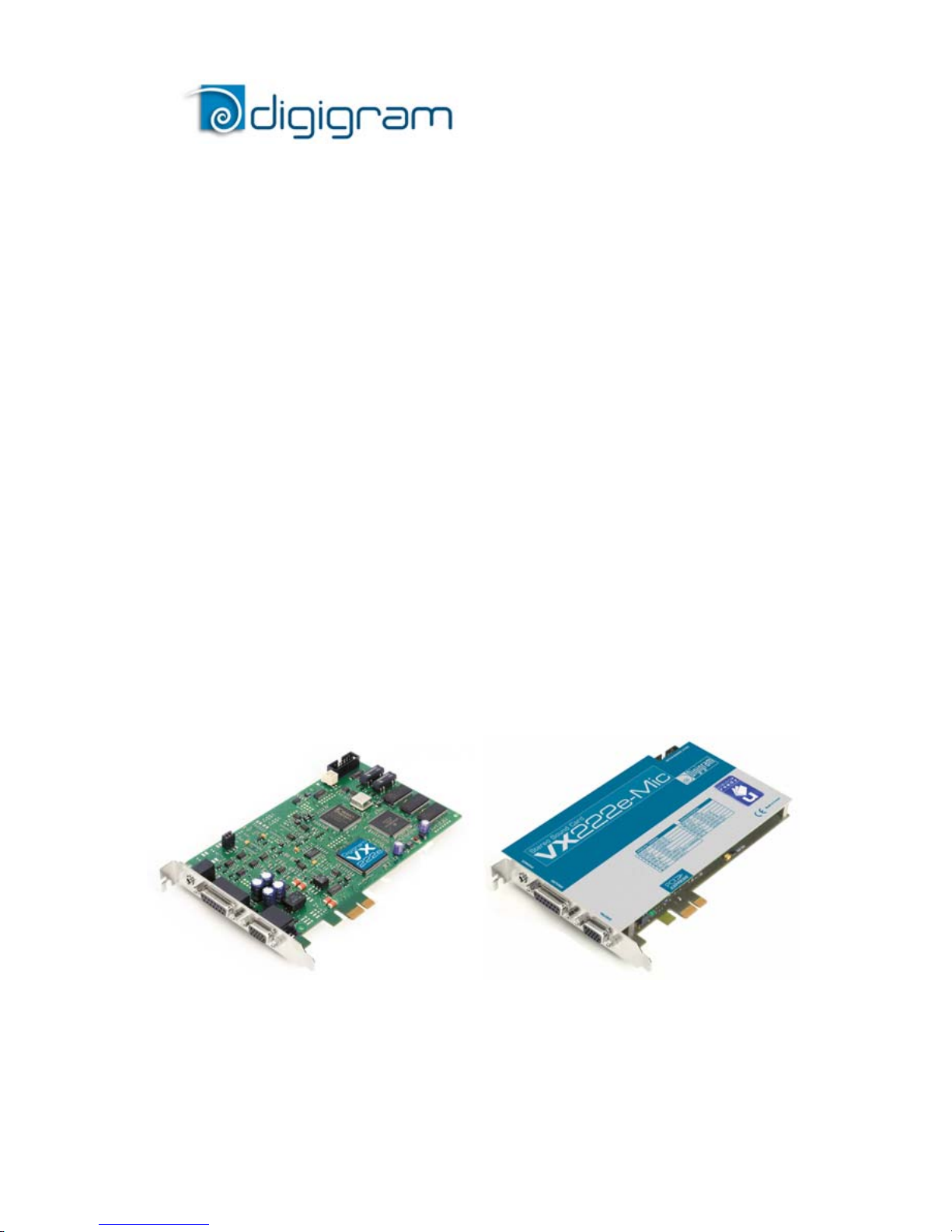
VX222e
VX222e-Mic
Professional Stereo
Sound Cards
User manual

2
For technical support,
please contact your system supplier
Digigram S.A.
82/84 Allée Galilée, 38330 Montbonnot-Saint-Martin, FRANCE
Tel: +33 (0)4 76 52 47 47• Fax: +33 (0) 4 76 52 18 44• E-mail: info@digigram.com
Digigram Inc.
2000 North 14th Street - Suite 530, Arlington, VA 22201, USA
Tel: +1 703 875 9100 • Fax: +1 703 875 9161 • E-mail: input@digigram.com
Digigram Asia Pte Ltd.
60 Albert Street - #19-11OG Albert Complex Singapore 189969, Singapore
Tel : +65 6291 2234 • Fax : +65 6291 3433 • E-mail : info_asia@digigram.com

VX222e & VX222e-Mic
User Manual
3
Table of Contents
INFORMATION FOR THE USER
.......................................................................5
IMPORTANT NOTICE
................................................................................................5
CONTENTS OF THIS PACKAGE
.......................................................................6
FEATURES
.............................................................................................................................6
VX222e & VX222e-Mic main hardware features .....................................................6
Additional hardware features VX222e-Mic ..................................................................7
Main software features ......................................................................................................7
HARDWARE REQUIREMENTS
..........................................................................8
Minimum requirements...................................................................................................... 8
Software requirements........................................................................................................8
Supported operating systems............................................................................................ 8
HARDWARE INSTALLATION
............................................................................8
Installing the card................................................................................................................. 8
Interrupt and memory address......................................................................................... 8
SOFTWARE INSTALLATION
................................................................................9
Standard installation under Windows XP, Server 2003,
and Windows Vista..............................................................................................................9
Parameterizing the ASIO and Wave drivers .............................................................. 11
Removing the driver under Windows XP and Server 2003................................... 12
Removing the driver under Windows Vista ................................................................ 12
HOW TO CHECK THE INSTALLATION
.................................................. 12
THE ‘DIGIGRAM HARDWARE SETTINGS’ (‘DHS’)
CONTROL PANEL
....................................................................................................... 14
SPECIFICATIONS
......................................................................................................... 15
Configuration...................................................................................................................... 15
Inputs ................................................................................................................................... 15
Additional inputs VX222e-Mic ...................................................................................... 16
Outputs................................................................................................................................ 16
Connectors .......................................................................................................................... 16
Audio specifications........................................................................................................... 17
Analog audio performance.............................................................................................. 17
Sample rate converter performance ............................................................................ 17
Analog mono microphone input features VX222e-Mic .......................................... 18
AES42 microphone input features - VX222e-Mic ................................................... 18
Development environments............................................................................................ 19
4
APPENDICES
.................................................................................................................... 20
VX222e schematic diagram........................................................................................... 20
VX222e-Mic schematic diagram .................................................................................. 20
Layout................................................................................................................................... 21
VX222e - analog cable diagram................................................................................... 22
VX222e-Mic - analog cable diagram........................................................................... 22
Wiring diagram - analog cable VX222e..................................................................... 23
Wiring diagram - analog cable VX222e..................................................................... 23
VX222e - digital cable with GPIOs............................................................................... 24
VX222e - digital cable without GPIOs......................................................................... 24
Wiring diagram - digital cable with GPIOs (VX222e) ............................................. 25
Wiring Diagram - digital cable without GPIOs (VX222e) ...................................... 25
VX222e-Mic - digital cable with GPIOs....................................................................... 26
VX222e-Mic - digital cable without GPIOs................................................................. 26
Wiring diagram - digital cable with GPIOs (VX222e-Mic) ..................................... 27
Wiring diagram - digital cable without GPIOs (VX222e-Mic) ...............................27
VX222e cable pinout....................................................................................................... 28
VX222e-Mic cable pinout............................................................................................... 28
Warning:
Electrostatic discharge (ESD) can damage several
components on the board. To avoid such damage in
handling the board, take the following precautions:
Bring the device and everything that contacts it to
ground potential by providing a conductive surface and
discharge paths. As a minimum, observe these
precautions:
• Disconnect all power and signal sources.
• Place the device on a grounded conductive work surface.
• Ground yourself via a grounding wrist strap or by holding a grounded
object.
• Ground any tool that will contact the device.
Due to the reduced length of the PCI EXPRESSTM bus connector and the
resulting lack of mechanical stability, we strongly advise against transporting
the card(s) installed in a computer, unless its chassis or case provides a
dedicated support to keep the card securely in place in order to avoid physical
damage.
Copyright 2007 – 2010 Digigram. All rights reserved.
No portion of this manual may be reproduced without prior written consent from Digigram. The copyright protection
claimed here includes photocopying, translation and/or reformatting of the information contained in this manual.
While every effort has been made to ensure accuracy, Digigram is not responsible for errors and omissions, and
reserves the right to make improvements or changes in the products and programs described without notice.
Digigram and the Digigram logo, VX222e and VX222e-Mic are registered trademarks or trademarks of Digigram S.A..
All other trademarks are property of their respective holders.

VX222e & VX222e-Mic
User Manual
5
INFORMATION FOR THE USER
This device complies with part 15 of FCC rules. Operation is subject to the following
two conditions: (1) This device may not cause harmful interference, and (2) This device
must accept any interference received, including interference that may cause undesired
operation.
This equipment has been tested and found to comply with the limits for a CLASS B
digital device, pursuant to Part 15 of the FCC Rules. These limits are designed to
provide reasonable protection against harmful interference in a residential installation.
This equipment generates, uses, and can radiate radio frequency energy and, if not
installed and used in accordance with the instructions contained in this data sheet, may
cause harmful interference to radio and television communications. However, there is
no guarantee that interference will not occur in a particular installation.
If this equipment does cause harmful interference to radio or television reception, which
can be determined by turning the equipment off and on, the user is encouraged to try to
correct the interference by one or more of the following measures:
* reorient or relocate the receiving antenna
* increase the separation between the equipment and the receiver
* connect the equipment into an outlet on a circuit different from that of the receiver
* consult the dealer or an experienced audio television technician.
Note: Connecting this device to peripheral devices that do not comply with CLASS B
requirements or using an unshielded peripheral data cable could also result in
harmful interference to radio or television reception. The user is cautioned
that any changes or modifications not expressly approved by the party
responsible for compliance could void the user’s authority to operate this
equipment. To ensure that the use of this product does not contribute to
interference, it is necessary to use shielded I/O cables.
IMPORTANT NOTICE
This card has been tested and found to comply with the following standards:
• International: CISPR22 Class B.
• Europe: EMC 89/336/CEE (1992) specifications.
• United States: FCC Rules-Part 15-Class B (digital device).
In order to guarantee compliance with the above standards in an installation, the
following must be done:
• the provided cable must not be modified.
• additional cables used must have their respective shield connected to each
extremity.
6
CONTENTS OF THIS PACKAGE
Thank you for purchasing a Digigram VX sound card.
The package consists of the following components:
• a VX222e or VX222e-Mic sound card
• the User’s Manual at hand.
The end user version additionally includes:
• two breakout cables (analog and digital)
• a CD-Rom with drivers, installation notices, FAQs, etc…
• a registration form
For the OEM version, the cables are available optionally.
FEATURES
VX222e and VX222e-Mic are audio cards for PCI EXPRESSTM (PCIe®) bus.
They are in PCI EXPRESS
TM
x1 format and can thus be plugged into any PCIe®
slot (x1, x2, x4, x8, x16, x32).
VX222e & VX222e-Mic main hardware features
• 2 balanced
∗
analog mono line inputs, with software adjustable gain and a
maximum input level of +24 dBu
• 2 servo-balanced
∗∗
analog mono line outputs, with software adjustable
gain and a maximum output level of +24 dBu
• 1 AES/EBU
∗∗∗
stereo input
The selection of the digital input for recording excludes the selection of
the analog inputs.
It is possible to use the signal on the digital input as reference clock.
• 1 AES/EBU
∗∗∗
stereo output
Always transmits the digital version of the analog outputs 1 and 2.
• 1 LTC (Linear Time Code) input
• 1 mini jack headphone stereo output
This output is in parallel of the analog outputs 1 and 2.
• 2 General Purpose inputs and 2 outputs (GPIOs)
• Inter-card synchronization connector
∗
can be used with unbalanced signals
∗∗
electronically servo-balanced outputs provide automatic level adjustment to accommodate
either balanced or unbalanced lines
∗∗∗
can be used as S/PDIF interface as well

VX222e & VX222e-Mic
User Manual
7
Additional hardware features VX222e-Mic
• 1 analog microphone input with
- high-quality preamplifier
- switchable 48 V phantom power
- analog expander/compressor/limiter
This input is mixed with the two line inputs before A/D conversion.
• 1 AES/EBU Sync input
∗
• The AES/EBU input is AES42 compatible (for connecting digital
microphone) and features a hardware sample rate converter
∗
(for details
see chapter ‘Specifications’)
The two AES/EBU inputs on the VX222e-Mic allow:
- recording of a digital signal on the AES/EBU data input; this input is
also used as source of synchronization with a digital clock
- recording of a digital signal on the AES/EBU data input, synchronized
on a digital clock connected to the AES/EBU synchronization input;
- the synchronization of analog recording and playback on an AES/EBU
clock connected to the AES/EBU Sync input.
The selection of the digital input excludes the selection of the analog
inputs.
Main software features
• Real-time, simultaneous PCM record and playback (8, 16 and 24 bits),
Float IEEE754 (with 24-bit fixed-point dynamic range)
• When using the np SDK, real-time on-board mixing of several PCM
audio streams, direct monitoring, level adjustment, panning, cross-fades,
punch-in/punch-out, scrubbing
• Possibility to control the parameters of the inputs and outputs (gains,
mutes, 48 V switch, analog compressor-limiter-expander parameters),
from the provided ‘Digigram Hardware Settings’ application, or from any
application that addresses these controls
• 24-bit DSP effects in playback and recording: 3-band parametric
equalizer plus Maximizer
• Low latency DirectSound, ASIO, and Wave
∗∗
drivers
Note: the HR Runtime package for Windows Vista does not include a Wave
driver. In case your audio application explicitly requires a Wave
interface, a Wave driver is available on request. In this case, please
contact Digigram
.
∗
AES/EBU sync input and hardware sample rate converter on the AES/EBU input on special
request on VX222e
∗∗
Windows XP and Server 2003 only
8
HARDWARE REQUIREMENTS
Minimum requirements
PC with one free PCI EXPRESSTM (PCIe®) slot (x1, x2, x4, x8, x16 or x32).
CPU power and memory required depend on the operating system and on the
audio application used.
Software requirements
To use your VX222e or VX222e-Mic, install the driver from the HR Runtime
package version 1.70 or higher. This package includes:
• a Digigram np driver enabling OEM applications to best capitalize on the
boards
• a WDM DirectSound driver
• a Wave driver
∗
(32 bits, installation optional)
• an ASIO driver (32 bits, installation optional)
Supported operating systems
VX222e and VX222e-Mic cards run under Windows XP, Windows Vista,
Windows Server 2008, and Windows 7.
HARDWARE INSTALLATION
Due to the reduced length of the PCI EXPRESSTM bus connector and the
resulting lack of mechanical stability, we strongly advise against transporting the
card(s) installed in a computer, unless its chassis or case provides a dedicated
support to keep the card securely in place in order to avoid physical damage.
The card has to be installed in the computer prior to installing its driver.
Installing the card
Gently plug the card into a free PCIe
®
slot and press it down firmly to position
it. Tighten the screw.
Interrupt and memory address
Hardware interrupt and addresses are automatically set up at start-up by the
PCI PnP BIOS.
∗ Windows XP and Server 2003 only; for Windows Vista, a Wave driver is available on
request.

VX222e & VX222e-Mic
User Manual
9
SOFTWARE INSTALLATION
Note: the installation of the software requires administrator rights on your
computer
Please visit the Digigram web site at www.digigram.com for the most recent
driver.
In case you run a specific application developed or installed by a Digigram
partner, it might require the use of a specific driver version. In this case, make
sure that the updated driver has been approved by your supplier.
Standard installation under Windows XP,
Windows Server 2003, and Windows Vista
If the driver has been downloaded from our web site, it has to be expanded
prior to the driver’s installation as follows: double-click on the downloaded
file (self-expanding). You can use the default destination location (Windows
temporary folder) or select another directory.
Important note
: this default procedure installs the ‘Digigram Hardware Settings’
control panel. This application allows the configuration of the hardware resources of
Digigram cards for all audio applications. The DHS allows for instance to define the
clock of the card, the input source, input and output analog and digital gain,
Sample Rate Converters, digital output format, etc...
Please note that, with the DHS installed, controls available through the DirectSound
control panel are limited to:
• Volume control for input and output
• Wave control
Under Windows XP, and Server 2003 you may also install the driver without
installing the DHS control panel, and in this case more controls are available
through the DirectSound
control panel:
• Volume control for input
• Wave control
• Monitoring control
• Analog input level
• Digital input level
• Clock selection: AES Sync, AES1, Word Clock
• Digital output format: professional, consumer
 Loading...