

Digigram PCX924v2, PCX924-Mic, PCX22v2 User Manual
D i g i g r a m
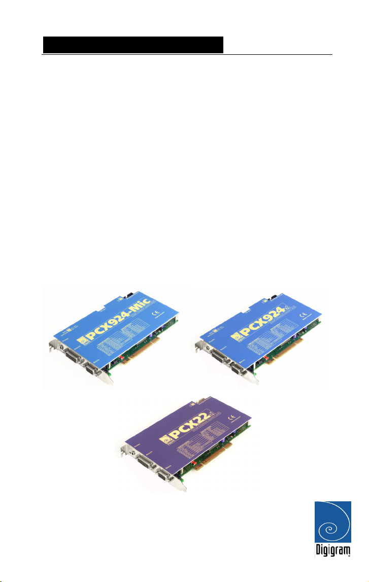
PCX924
v2
PCX924-Mic
PCX22
Professional Stereo Sound Cards
v2
User’s manual

D i g i g r a m
For technical support,
please contact your system supplier.
Digigram S.A.
Parc de Pré Milliet, 38330 Montbonnot - FRANCE
Tel: +33 (0)4 76 52 55 01• Fax: +33 (0) 4 76 52 53 07• E-mail: info@digigram.com
Digigram Inc.
2101 Wilson Boulevard, Suite 1004, Arlington, VA 22201-USA
Tel: +1 703 875 9100 • Fax: +1 703 875 9161 • E-mail: input@digigram.com
Digigram Asia Pte Ltd.
350 Orchard Road - #19-07 Shaw House Singapore 238868-SINGAPORE
Tel: +65 6291 2234 • Fax: +65 6291 3433 • E-mail: info_asia@digigram.com
2

PCX924v2 , PCX924-Mic & PCX22v2
User’s Manual
Table of Contents
INFORMATION FOR THE USER
IMPORTANT NOTICE
CONTENTS OF THIS PACKAGE
FEATURES
Main hardware features ................................................................................................. 6
PCX924v2 and PCX924-Mic....................................................................................6
PCX924-Mic additional hardware features..........................................................7
PCX22v2 ........................................................................................................................7
Main software features................................................................................................... 7
PCX924v2 and PCX924-Mic....................................................................................7
PCX22v2 ........................................................................................................................8
PCX924-Mic additional software features ...........................................................8
PCX924v2 and PCX22v2 optional software features.........................................8
HARDWARE REQUIREMENTS
Minimum requirements................................................................................................... 8
SOFTWARE REQUIREMENTS
Supported operating systems ........................................................................................9
HARDWARE INSTALLAT ON
Installing the card .............................................................................................................9
Interrupt and memory address .....................................................................................9
SOFTWARE INSTALLATION
Installation under Windows 98 SE and Millennium ............................................. 10
Removing the driver under Windows 98 SE and Millennium............................ 11
Installation under Windows 2000 and XP ............................................................. 12
Removing the driver under Windows 2000 and XP ............................................ 13
HOW TO CHECK THE INSTALLATION
SPECIFICATIONS
CONFIGURATION (all cards)................................................................................ 15
INPUTS / OUTPUTS (PCX924v2 and PCX924-Mic)...................................... 15
INPUTS / OUTPUTS (PCX22v2)........................................................................... 16
AUDIO SPECIFICATIONS....................................................................................... 16
PCX924-Mic SPECIAL FEATURES....................................................................... 17
PERFORMANCE ....................................................................................................... 17
PCX924v2 & PCX924-Mic: ................................................................................... 17
PCX22v2 ..................................................................................................................... 17
........................................................................................................................6
..........................................................................................5
I
................................................................................................... 15
.................................................................5
.................................................................6
.....................................................................8
........................................................................8
.......................................................................9
....................................................................... 10
............................................ 14
3

D i g i g r a m
APPENDICES
SCHEMATIC DIAGRAM PCX924-Mic................................................................18
SCHEMATIC DIAGRAM PCX924v2.....................................................................18
SCHEMATIC DIAGRAM PCX22v2 ....................................................................... 18
Layout PCX924v2 & PCX924-Mic....................................................................... 19
Layout PCX22v2........................................................................................................ 19
Switches ......................................................................................................................20
Connectors..................................................................................................................20
PCX924-Mic ANALOG CABLE DIAGRAM......................................................... 21
Wiring Diagram – Analog Cable PCX924-Mic.................................................21
PCX924v2 ANALOG CABLE DIAGRAM.............................................................. 22
Wiring Diagram – Analog Cable PCX924v2......................................................22
DIGITAL CABLE with GPIOs (PCX924-Mic & PCX924v2) ............................ 23
DIGITAL CABLE without GPIOs (PCX924-Mic & PCX924v2) ...................... 23
Wiring Diagram – Digital Cable with GPIOs (PCX924-Mic & PCX924v2)..........24
Wiring Diagram – Digital Cable without GPIOs (PCX924-Mic & PCX924v2).... 24
PCX924-Mic CABLE PINOUT............................................................................... 25
PCX924v2 CABLE PINOUT.................................................................................... 25
PCX22v2 ANALOG CABLE DIAGRAM ................................................................26
Wiring Diagram – Analog Cable PCX22v2 ........................................................26
PCX22v2 DIGITAL CABLE with GPIOs ................................................................ 27
PCX22v2 DIGITAL CABLE without GPIOs .......................................................... 27
Wiring Diagram – Digital Cable with GPIOs (PCX22v2)................................ 28
Wiring Diagram – Digital Cable without GPIOs (PCX22v2).......................... 28
PCX22v2 CABLE PINOUT ...................................................................................... 28
Copyright 2004 Digigram. All rights reserved.
No portion of this manual may be reproduced without prior written consent from Digigram. The copyright protection
claimed here includes photocopying, translation and/or reformatting of the information contained in this manual.
While every effort has been made to ensure accuracy, Digigram is not responsible for errors and omissions, and
reserves the right to make improvements or changes in the products and programs described without notice.
Digigram, PCX924, and PCX22 are registered trademarks or trademarks of Digigram S.A. Other trademarks are
property of their respective holders.
.............................................................................................................. 18
4

PCX924v2 , PCX924-Mic & PCX22v2
User’s Manual
INFORMATION FOR THE USER
This device complies with part 15 of FCC rules. Operation is subject to the following
two conditions: (1) This device may not cause harmful interference, and (2) This device
must accept any interference received, including interference that may cause undesired
operation.
This equipment has been tested and found to comply with the limits for a CLASS B
digital device, pursuant to Part 15 of the FCC Rules. These limits are designed to
provide reasonable protection against harmful interference in a residential installation.
This equipment generates, uses, and can radiate radio frequency energy and, if not
installed and used in accordance with the instructions contained in this data sheet, may
cause harmful interference to radio and television communications. However, there is
no guarantee that interference will not occur in a particular installation.
If this equipment does cause harmful interference to radio or television reception, which
can be determined by turning the equipment off and on, the user is encouraged to try to
correct the interference by one or more of the following measures:
* reorient or relocate the receiving antenna
* increase the separation between the equipment and the receiver
* connect the equipment into an outlet on a circuit different from that of the receiver
* consult the dealer or an experienced audio television technician.
Note: Connecting this device to peripheral devices that do not comply with CLASS B
requirements or using an unshielded peripheral data cable could also result in
harmful interference to radio or television reception. The user is cautioned
that any changes or modifications not expressly approved by the party responsible
for compliance could void the user’s authority to operate this equipment. To ensure
that the use of this product does not contribute to interference, it is necessary to use
shielded I/O cables.
IMPORTANT NOTICE
This card has been tested and found to comply with the following standards:
• International: CISPR22 Class B.
• Europe: EMC 89/336/CEE (1992) specifications.
• United States: FCC Rules-Part 15-Class B (digital device).
In order to guarantee compliance with the above standards in an installation,
the following must be done:
• the provided cables must not be modified.
• additional cables used must have their respective shield connected to
each extremity.
5

D i g i g r a m
CONTENTS OF THIS PACKAGE
Thank you for purchasing a Digigram PCX924 or PCX22
The package consists of the following components:
* a PCX924
v2, PCX924-Mic, or PCX22v2 sound card,
* the User’s Manual at hand.
The cables (optional) are delivered separately.
FEATURES
PCX924
v2, PCX924-Mic, and PCX22v2 are audio cards for PCI bus. They are
‘Universal PCI 32-bit/33 MHz’, which means they can be plugged in 5 V PCI
slots as well as in 3.3 V keyed PCI slots. The cards are also compatible with
PCI-X interfaces.
Main hardware features
PCX924v2 and PCX924-Mic
• 2 balanced analog mono line inputs, with:
- Software programmable analog and digital gain
- Input impedance selection (600 Ω, >10 KΩ) via switches on the card
(see top cover of the card)
• 2 servo-balanced
programmable analog and digital gain
• 1 digital AES/EBU
• 1 digital AES/EBU
These two AES/EBU inputs allow:
- recording of a digital signal on the AES/EBU synchronization input
- recording of a digital signal on the AES/EBU data input, synchronized
on a digital clock connected to the AES/EBU synchronization input.
- synchronization of analog record/playback on an AES/EBU clock
The selection of the digital input for recording excludes the selection of
the analog inputs.
• 1 digital AES/EBU
Always plays the digital version of the analog outputs 1 and 2.
∗
analog mono line outputs, with software
∗∗
stereo input, for synchronization
∗∗
stereo input, for digital data only
∗∗
stereo output
v2 card.
∗
Electronically servo-balanced outputs provide automatic level adjustment to accommodate
either balanced or unbalanced lines
∗∗
can be used as S/PDIF interface as well
6

PCX924v2 , PCX924-Mic & PCX22v2
User’s Manual
• 1 CD-ROM input
• 1 SMPTE-LTC (longitudinal time code) input
• Variable programmable sampling clock, from 8 kHz to 50 kHz .
• 1 mini jack headphone stereo output
(This output is in parallel of the analog outputs 1 and 2)
• 2 General Purpose inputs and 2 outputs (GPIOs)
• Inter-card synchronization connector
If this connector is not used, synchro switches must be ON.
If it is used, one of the connected cards must have the synchro switches
ON, all the other linked cards must have the switches OFF.
PCX924-Mic additional hardware features
• 1 microphone input with switchable 48 V phantom power, and analog
expander/compressor/limiter
This input and the line input are mixed together before analog to digital
conversion.
PCX22v2
• 2 servo-balanced∗ analog mono line outputs, with software
programmable analog and digital gain
• 1 digital AES/EBU
• 1 digital AES/EBU
(Always plays the digital version of the analog outputs 1 and 2)
• 1 mini jack headphone stereo output
(This output is in parallel of the analog outputs 1 and 2)
• 2 General Purpose inputs and 2 outputs (GPIOs)
• Inter-card synchronization connector
If this connector is not used, synchro switches must be ON.
If it is used, one of the connected cards must have the synchro switches
ON, all the other linked cards must have the switches OFF.
∗∗
synchronization input
∗∗
stereo output
Main software features
PCX924v2 and PCX924-Mic
• Decoding and mixing of several PCM (8, 16 and 24 bits) and MPEG
Audio streams (Layer 1, II & III)
• Real-time, simultaneous record and playback in PCM (8, 16 and 24 bits)
as well as in MPEG Audio layer I and layer II
∗
Electronically servo-balanced outputs provide automatic level adjustment to accommodate
either balanced or unbalanced lines
∗∗
can be used as S/PDIF interface as well
7

D i g i g r a m
• When using the np SDK:
- panning, cross-fades, punch-in/punch-out, scrubbing, time stretching, pitch-shifting, format and frequency conversions
- inter-board synchronization of multiple PCX924 cards in one PC
- synchronization via an LTC (SMPTE) time code input
PCX22
• Decoding and mixing of several PCM (8, 16 and 24 bits) and MPEG
• When using the np SDK:
PCX924-Mic additional software features
• Software control of the microphone input:
• Additional 24-bit DSP effects on the output in playback:
v2
Audio streams (Layer 1, II & III)
- panning, cross-fades, scrubbing, time-stretching, pitch-shifting, format
and frequency conversions
gain, 48 V switch, analog compressor-limiter-expander parameters
3-band parametric equalizer and Maximizer
PCX924v2 and PCX22
• Additional 24-bit DSP effects on the output in playback:
3-band parametric equalizer and Maximizer
v2
optional software features
HARDWARE REQUIREMENTS
PCX924v2, PCX924-Mic, and PCX22v2 cards have been developed for IBM and
IBM-compatible PC systems.
Minimum requirements
• Pentium III minimum (or equivalent)
• 128 MB RAM
• One free PCI slot (5 V or 3.3 V)
SOFTWARE REQUIREMENTS
To use your PCX924v2 or PCX22v2 card, you have to install the driver from the
np Runtime package version 6.01 or higher.
The PCX924-Mic requires the installation of np Runtime version 6.30 or
higher.
These packages also include a Wave driver that may be installed so that the
card can be used with standard multimedia applications.
8

PCX924v2 , PCX924-Mic & PCX22v2
User’s Manual
Supported operating systems
PCX924v2 and PCX22v2 cards run under Windows 98 (SE and Millennium),
Windows 2000, and Windows XP, the PCX924-Mic under Windows 2000
and Windows XP only.
HARDWARE INSTALLATION
Note: Under Windows 2000 and XP, the card has to be installed in the
computer prior to installing its driver.
Under Windows 9x, first install the driver, and then insert the card.
Installing the card
Gently plug the card in a free PCI slot and press it down to position it firmly.
Tighten the screw.
Interrupt and memory address
Hardware interrupt and addresses are automatically set up at start-up by the
PCI PnP BIOS.
WARNING
The PCX924-Mic includes a microphone pre-amplifier, which is sensitive to
electro-magnetic perturbations.
In order to avoid spurious noise when using the microphone input, we
recommend not to install the PCX924-Mic close to another card equipped
with a fan. If this happens try to have some free slots between the two cards.
9
 Loading...