

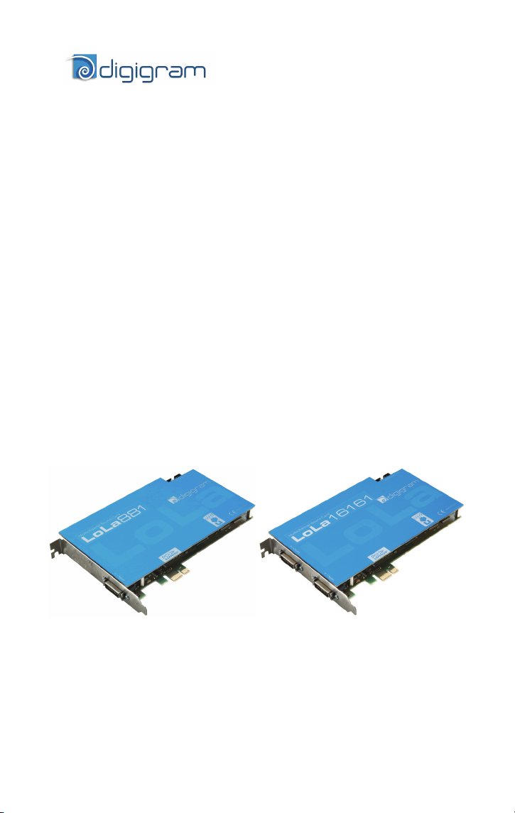
LoLa881
LoLa16161
Professional
Multichannel Sound Cards
User manual

For technical support
please contact your system supplier
Digigram S.A.
82/84 Allée Galilée, 38330 Montbonnot-Saint-Martin, FRANCE
Tel: +33 (0)4 76 52 47 47• Fax: +33 (0) 4 76 52 18 44• E-mail: info@digigram.com
Digigram Inc.
2000 North 14th Street - Suite 530, Arlington, VA 22201, USA
Tel: +1 703 875 9100 • Fax: +1 703 875 9161 • E-mail: input@digigram.com
Digigram Asia Pte Ltd.
60 Albert Street - #19-11OG Albert Complex Singapore 189969, Singapore
Tel : +65 6291 2234 • Fax : +65 6291 3433 • E-mail : info_asia@digigram.com
2

LoLa881 & LoLa16161
User manual
Table of Contents
INFORMATION FOR THE USER
IMPORTANT NOTICE
.......................................................................................................................5
CONTENTS OF THIS PACKAGE
FEATURES
LoLa881 main hardware features..........................................................................................................6
LoLa16161 main hardware features..................................................................................................... 6
Main software features..............................................................................................................................6
.....................................................................................................................................................6
MINIMUM REQUIREMENTS
Minimum hardware requirements.......................................................................................................... 7
Software requirements...............................................................................................................................7
OS supported ...............................................................................................................................................7
HARDWARE INSTALLATION
Installing the card........................................................................................................................................ 7
Interrupt and memory address................................................................................................................ 7
SOFTWARE INSTALLATION
Installation under Windows XP, Windows Server 2003, Windows Server 2008,
Windows Vista, Server 2008, and Windows 7 ................................................................................... 8
The ASIO Control panel.....................................................................................................................9
‘LoLa Manager’ control panel ....................................................................................................... 10
Removing the driver under Windows XP and Windows Server 2003....................................... 11
Removing the driver under Windows Vista, Server 2008, and Windows Server 7................ 11
HOW TO CHECK THE INSTALLATION
SPECIFICATIONS
Configuration ..................................................................................................................................... 16
Inputs................................................................................................................................................... 16
Outputs ............................................................................................................................................... 17
Connectors ......................................................................................................................................... 17
Audio specifications.......................................................................................................................... 17
Development environments........................................................................................................... 18
APPENDICES
LoLa881/16161 schematic diagram .......................................................................................... 19
LoLa881 Connector ......................................................................................................................... 20
LoLa16161 Connector.................................................................................................................... 20
LoLa881/16161, AES 1 – 4 and sync cable connector......................................................... 21
Wiring diagram LoLa881/16161, AES 1 – 4 and sync......................................................... 21
Wiring diagram LoLa881/16161, AES 5 - 8............................................................................ 22
Pinout - LoLa881/16161, AES 1 – 4 and sync........................................................................ 23
Copyright 2009 - 2010 Digigram. All rights reserved.
No portion of this manual may be reproduced without prior written consent from Digigram. The copyright protection
claimed here includes photocopying, translation and/or reformatting of the information contained in this manual.
While every effort has been made to ensure accuracy, Digigram is not responsible for errors, omissions or typos and
reserves the right to make improvements or changes in the products and programs described without notice.
Digigram and the Digigram logo, and LoLa881/16161 are registered trademarks or trademarks of Digigram S.A.. Other
trademarks are property of their respective holders.
Pinout - LoLa16161, AES 5 - 8 .................................................................................................... 23
................................................................................................................................. 16
........................................................................................................................................... 19
..............................................................................................4
..............................................................................................5
........................................................................................................7
....................................................................................................7
.......................................................................................................8
.......................................................................... 11
3
INFORMATION FOR THE USER
This device complies with part 15 of FCC rules. Operation is subject to the following
two conditions: (1) This device may not cause harmful interference, and (2) This device
must accept any interference received, including interference that may cause undesired
operation.
This equipment has been tested and found to comply with the limits for a CLASS B
digital device, pursuant to Part 15 of the FCC Rules. These limits are designed to
provide reasonable protection against harmful interference in a residential installation.
This equipment generates, uses, and can radiate radio frequency energy and, if not
installed and used in accordance with the instructions contained in this data sheet, may
cause harmful interference to radio and television communications. However, there is
no guarantee that interference will not occur in a particular installation.
If this equipment does cause harmful interference to radio or television reception, which
can be determined by turning the equipment off and on, the user is encouraged to try to
correct the interference by one or more of the following measures:
* reorient or relocate the receiving antenna
* increase the separation between the equipment and the receiver
* connect the equipment into an outlet on a circuit different from that of the receiver
* consult the dealer or an experienced audio television technician.
Note: Connecting this device to peripheral devices that do not comply with CLASS B
requirements or using an unshielded peripheral data cable could also result in
harmful interference to radio or television reception. The user is cautioned
that any changes or modifications not expressly approved by the party
responsible for compliance could void the user’s authority to operate this
equipment. To ensure that the use of this product does not contribute to
interference, it is necessary to use shielded I/O cables.
Warning:
Electrostatic discharge (ESD) can damage several
components on the board. To avoid such damage in
handling the board, take the following precautions:
Bring the device and everything that contacts it to
ground potential by providing a conductive surface and
discharge paths. As a minimum, observe these
precautions:
• Disconnect all power and signal sources.
• Place the device on a grounded conductive work surface.
• Ground yourself via a grounding wrist strap or by holding a grounded
object.
• Ground any tool that will contact the device.
4

LoLa881 & LoLa16161
User manual
IMPORTANT NOTICE
This card has been tested and found to comply with the following standards:
• International: CISPR22 (2005) Class B.
• Europe: EMC 2004/108/CE specifications.
• United States: FCC Rules-Part 15-Class B (digital device).
In order to guarantee compliance with the above standards in an installation, the
following must be done:
• the provided cable must not be modified.
• additional cables used must have their respective shield connected to each
extremity.
Due to the reduced length of the PCI EXPRESS
resulting lack of mechanical stability, we strongly advise against transporting
the card(s) installed in a computer, unless its chassis or case provides a
dedicated support to keep the card securely in place in order to avoid physical
damage.
CONTENTS OF THIS PACKAGE
You have just acquired a LoLa sound card by Digigram and we congratulate
you!
The package consists of the following components:
• A flyer indicating the web address of the product page with information
on downloading drivers, firmware, documentation…
• a LoLa881 or LoLa16161 sound card
The end user version additionally includes:
• A primary cable
• a secondary cable (LoLa16161 only)
For the OEM version, the cables are available optionally.
TM
bus connector and the
5
FEATURES
LoLa881 and LoLa16161 are audio cards for PCI EXPRESSTM (PCIe®) bus.
They come in PCI EXPRESS
slot (x1, x2, x4, x8, x16, x32).
LoLa881 main hardware features
• 4 AES/EBU inputs∗ with h/w frequency converters (up to 192 kHz)
• 4 AES/EBU∗ outputs (up to 192 kHz)
• 1 AES/EBU∗ sync input (up to 192 kHz in play and record)
• 1 standard Word Clock input (up to 192 kHz)
• 1 standard Word Clock output (up to192 kHz)
• 1 PAL/NTSC video sync input
LoLa16161 main hardware features
• 8 AES/EBU inputs∗ with h/w frequency converters (up to 192 kHz)
• 8 AES/EBU outputs∗ (up to 192 kHz)
• 1 AES/EBU sync input
• 1 standard Word Clock input (up to 192 kHz)
• 1 standard Word Clock output (up to192 kHz)
• 1 PAL/NTSC video sync input
Main software features
• Real-time, simultaneous record and playback in PCM (8, 16 and 24 bits
and 32 bits Float)
• LoLa Manager application by Digigram allowing to easily configure and
control the boards.
• Low latency DirectSound and ASIO
TM
format and can thus be plugged into any PCIe®
∗
(up to 192 kHz in play and record)
∗∗
drivers
∗
can be used as S/PDIF interfaces as well
∗∗
supporting 32-bit ASIO applications
6

LoLa881 & LoLa16161
User manual
MINIMUM REQUIREMENTS
Minimum hardware requirements
PC with one free PCI EXPRESSTM (PCIe®) slot (x1, x2, x4, x8, x16 or x32).
The power of the processor and the memory depend on application and
operating system used on the PC.
Software requirements
The LoLa881/16161 requires installation of the drivers included in the LoLa
Kit version 1.03 or higher.
The LoLa Kit includes:
• a WDM DirectSound driver
• an ASIO driver
• LoLa Manager application to configure and control the boards
OS supported
LoLa881 and LoLa16161 run under Windows XP, Windows Server 2003,
Windows Server 2008, Windows Vista, and Windows 7.
HARDWARE INSTALLATION
Due to the reduced length of the PCI EXPRESSTM bus connector and the resulting
lack of mechanical stability, we strongly advise against transporting the card(s)
installed in a computer, unless its chassis or case provides a dedicated support to
keep the card securely in place in order to avoid physical damage.
The card has to be installed in the computer prior to installing its driver.
Installing the card
Gently plug the card in a free PCIe® slot and press it down to position it
firmly. Tighten the fastening screw of the bracket, or lock the card by means
of the mechanism provided for this purpose on your computer.
∗
∗
supporting 32-bit ASIO applications
7
 Loading...