


Digigram
Networking Your Sound
ES8in
ES8mic
ES8out
U
SER’ S M ANUAL
M
ANUEL UTILISATEUR
EtherSound ES8in, ES8mic & ES8out
Ethernet Audio Bridges
Important Safety Information
read carefully before using this equipment!
Follow these instructions and keep them in a safe place! Keep in mind that damages due to failure to
observe the instructions contained in this manual are not covered by warranty.
Instructions importantes de sécurité
lire soigneusement avant d'utiliser l'équipement!
Lisez et suivez ces instructions. Conservez les pour consultation ultérieure! Les dommages dus au
non-respect des instructions contenues dans ce manuel ne sont pas couverts par la garantie.
Wichtige Sicherheitshinweise
vor Inbetriebnahme des Gerätes sorgfältig lesen!
Befolgen Sie die Anweisungen und bewahren Sie sie für spätere Fragen auf! Bei Schäden, die durch
Nichtbeachten dieser Bedienungsanleitung verursacht werden, erlischt der Garantieanspruch!
Do Not Open the Cabinet
There are no user-serviceable
Opening the cabinet may present a shock hazard,
and any modification to the product will void
your warranty. If it is necessary to open the device
for maintenance or advanced configuration
purposes, this is to be done by qualified personnel
only after disconnecting the power cord and
network ca
manual and marked on the equipment. This
equipment must be earthed!
Do not block any of the ventilation openings!
Humidity
To reduce the risk of fire or shock, do not expose
this device to rain or moisture. Do not place
objects filled with liquid on this device.
Installation Location
To ensure proper operation and to avoid safety
hazards, the device must be installed in a 19“ rack
mount chassis. If this is not possible, place it on a
firm and level surface. Avoid installation in
extremely hot or cold locations, or in an area that
is exposed to direct sunlight or heating
equipment. Avoid moist or humid locations.
Cleaning
Clean only with a soft, dry cloth. If necessary,
after disconnecting the unit’s cables, wipe it with a
soft cloth dampened with mild soapy water, then
with a fresh cloth with clean water. Wipe dry
immediately with a dry cloth. NEVER use
benzene, aerosol cleaners, thinner, alcohol or any
other volatile cleaning agent. Do not use abrasive
cleaners, which may damage the finish of metal or
other parts.
Refer all servicing to qualified service
personnel.
Servicing is required when the apparatus has been
damaged in any way, such as power supply cord
or plug is damaged, liquid has been spilled, the
apparatus has been exposed to rain or moisture,
does not operate normally, or has been dropped.
Moving the device
Before moving the unit, be certain to disconnect
any cables that connect with other components.
components inside this product.
bles!
Power supply
The device is to be connected only to a
power supply as specified in this
modificatio
est nécessaire d'ouvrir l'appareil pour l'entretien
ou la configuration avancée, cela doit être fait par
du personnel qualifié, après avoir débranché le
cordon d'alimentation et les câbles réseaux !
ma
Cet équipement doit être raccordé à la terre !
N'obstruer aucune ouverture de ventilation !
Humidité
Afin de rédu
n'exposez pas cet appareil à la pluie ou l'humidité.
Ne placez pas d´objet contenant un liquide sur
l'appareil.
Installation
Afin d'assurer le fonctionne
minimiser les risques potentiels liés à la sécurité,
l'appareil doit être installé dans une baie de
montage de type 19 pouces. Si cela ne vous est
pas possible, placez le sur une surface solide et
plane.
Evitez
chauds ou très froids ainsi que dans des lieux
exposés directement au soleil. Evitez les lieux
présentant un excès d'humidité.
Nettoyage
Nettoyez un
Si nécessaire, après avoir débranché le cordon
d´alimentation, essuyez-le avec un chiffon doux
humidifié avec de l´eau savonneuse puis rincez le
á l´aide d un chiffon propre et d´eau claire.
Séchez-le immédiatement avec un chiffo
N'utilisez JAMAIS d´essence, de nettoyants en
aérosols, d´alcool ou tout autre agent nettoyant
volatile. N'utilisez pas de produits nettoyants
abrasifs qui pourraient endommager les finitions
métalliques ou d´autres pièces.
Réparation
Lorsque l'app
soit la cause ou qu'il ne fonctionne pas
normalement, toute réparation doit être effectuée
par du personnel qualifié. Avant de transporter
l´unité, assurez-vous d´avoir bien déconnecté le
cordon d'alimentation ainsi que tous les câbles la
reliant à d´autres appareils.
Ne pas ouvrir l'appareil
L'ouverture du coffret peut produire
un risque de choc électrique, et toute
n du produit annule votre garantie. S'il
Alimentation
Il est primo
l'appareil à une alimentation
électrique telle que spécifiée dans ce
u
tilisateur et sur le matériel même.
nuel d´
ire les risques de feu ou de choc,
, mise en place
une installation dans des endroits très
iquement avec un chiffon doux et sec.
areil a été endommagé quelle qu'en
rdial de connecter
ment correct et de
n sec.
Throughout this manual,
the lightning bolt triangle is
used to alert the user to the
risk of electric shock.
The exclamation point
triangle is used to alert the
user to important operating
or maintenance instructions.
Gerät nicht öffnen
Öffnen des Geräts kann eine
Gefährdung durch Stromschlag und
Erlöschen der Garantie zur Folge haben.
Reparaturarbeiten und Änderungen der
Hardwarekonfiguration dürfen nur von
qualifiziertem Personal nach entfernen der Stromund Netzwerkkabel durchgeführt werden.
Stromversorgung
Das Gerät darf nur mit der in dieser
Bedienungsanleitung und auf dem
Gerät angegebenen Stromversorgung
betrieben werden. Erdung ist zu gewährleisten!
Belüftungsschlitze nicht verdecken!
Wasser und Feuchtigkeit
Um Brand- oder Stromschlagrisiken zu
vermeiden, darf das Gerät nicht mit Feuchtigkeit
in Berührung kommen.
Aufbau des Geräts
Um den einwandfreien Betrieb zu gewährleisten
und Sicherheitsrisiken zu vermeiden, muss das
Gerät in einem 19-Zoll Baugruppenrahmen
montiert werden. Nur wenn dies nicht möglich
ist, stellen Sie das Gerät auf einen festen,
waagerechten Untergrund. Meiden Sie Standorten
in den Nähe von Wärme- oder
Feuchtigkeitsquellen sowie direkte
Sonneneinstrahlung.
Reinigen des Geräts
Säubern Sie das Gerät nur mit einem weichen,
trockenen Tuch. Bei Bedarf verwenden Sie ein mit
mildem Seifenwasser befeuchtetes Tuch, nachdem
Sie die Netzanschlusskabel aus der Steckdose
gezogen haben, anschliessend ein weiches, mit
klarem Wasser befeuchtetes Tuch. Trocken Sie
das Gerät sofort im Anschluss. Keinesfalls Benzol,
Verdünner oder sonstige starke Lösungsmittel
oder Scheuerreiniger verwenden, da hierdurch
das Gehäuse beschädigt werden könnte.
Lassen Sie etwaige Reparaturen nur von
qualifizierten Fachleuten durchführen!
Sollten das Netzkabel oder der Netzstecker
beschädigt sein, oder sollte das Gerät selbst
beschädigt worden sein (z. B. durch Eindringen
von Feuchtigkeit durch Fall auf den Boden), oder
sollte es nicht ordnungsgemäss funktionieren oder
eine deutliche Funktionsabweichung aufweisen,
so ist es von qualifizierten Fachleuten zu
reparieren.

D i g i g r a m
Table of Contents
INFORMATION FOR THE USER
Overview
Contents of this package
The ES8in/ES8mic and ES8out front panels
The ES8in/ES8mic and ES8out rear panels
XLR models............................................................................................................................................................. 6
Terminal block models ......................................................................................................................................... 6
INSTALLATION
Before mounting dev ces in a rack…
Internal settings (ES8in/ES8mic only)
C
onnecting your EtherSound device
Power ........................................................................................................................................................................ 8
Network ................................................................................................................................................................... 8
Co
Audio .........................................................................................................................................................................9
GPIO.......................................................................................................................................................................... 9
Serial port (RS232 on DB9) ............................................................................................................................ 10
.....................................................................................................................................................................4
................................................................................................................................4
....................................................................................................................................................8
i
Example 1: point-to-point transmission of eight audio channels......................................................... 8
Example 2: adding more devices.................................................................................................................9
Example 3: more complex architectures................................................................................................... 9
nnecting a computer to manage the EtherSound network.................................................................... 9
..........................................................................................................4
......................................................................................................8
...............................................................................................................8
.....................................................................................................8
......................................................................................5
.......................................................................................6
Setting the EtherSound channels
Manual set-up ..................................................................................................................................................... 10
ES8mic & ES8micCL management ............................................................................................................... 11
Remote set-up by means of configuration software .................................................................................. 11
Fi
rmware update
2
.............................................................................................................................................. 11
.......................................................................................................... 10

EtherSound ES8in, ES8mic & ES8out
Ethernet Audio Bridges
SPECIFICATIONS
Configuration
Parameters
............................................................................................................................................................12
Inputs/Outputs
..............................................................................................................................................12
.......................................................................................................................................................12
....................................................................................................................................................12
ES8micCL special features..........................................................................................................................12
Connectivity
Audio specifications
Synchronization
Appendix A: GPIO description
General Purpose Inputs (GPIs)
..........................................................................................................................................................13
.........................................................................................................................................13
..................................................................................................................................................13
........................................................................................................14
................................................................................................................14
GPI #1....................................................................................................................................................................14
GPI #2....................................................................................................................................................................14
GPI #3 & GPI #4 ................................................................................................................................................14
GPI optocoupler specifications..........................................................................................................................15
General Purpose Outputs (GPOs)
.........................................................................................................15
GPO relay specifications.....................................................................................................................................15
Appendix B: Setting the internal jumpers
Jumper locations on the main board
....................................................................................................16
........................................................................16
Sampling frequency.............................................................................................................................................17
Input impedance and nominal input level.....................................................................................................18
Appendix C: Glossary
.................................................................................................................................19
Copyright 2004 Digigram. All rights reserved.
No portion of this manual may be reproduced without prior written consent from Digigram. The copyright protection claimed here includes
photocopying, translation and/or reformatting of the information contained in this manual.
While every effort has been made to ensure accuracy, Digigram is not responsible for errors and omissions, and reserves the right to make improvements
or changes in the products and programs described without notice.
Digigram, EtherSound, ES8in, ES8mic, and ES8out are registered trademarks or trademarks of Digigram S.A. Other trademarks are p operty of their
respective holders.
EtherSound technology is protected by international patents and patent applications, including, but not limited to, the following: WO 03/023759, FR 2 829
655, US 2003/0050989
r
3

D i g i g r a m
Thank you for purchasing Digigram EtherSound ES8in/ES8mic/ES8out!
EtherSound ES8in, ES8mic, and ES8out by Digigram incorporate our patented EtherSound audio networking
technology. They offer the easiest and most affordable way to install and distribute up to 64 channels of
audio between up to 65 534 devices using standard Ethernet switches and cabling.
ES8in/ES8mic insert eight analog audio channels into an EtherSound network with ES8mic adding the
flexibility to connect up to eight microphones instead of the line inputs, while ES8out extracts eight analog
audio channels for playback. All three feature GPIOs and RS232 for bi-directional control and take
advantage of EtherSound's simple, nearly instant set-up.
EtherSound ES8in, ES8mic, and ES8out allow audio distribution going well beyond the possibilities of analog
audio installations and their physically defined signal paths. Routing can be adapted remotely to the
changing needs of the audio installation.
INFORMATION FOR THE USER
This equipment has been tested and found to comply with the limits for a CLASS B digital device, pursuant to Part 15 of the FCC
Rules and with the following European and international Standards for:
Electrical safety: Electromagnetic Compatibility:
Europe : EN60950, 3rd edition
European Directive 73/23/CEE “Low Voltage Directive“
International: IEC 60950, 3rd edition
Europe: EN55022:1998 + A1:2000, Class B / EN55024 : 1998 + A1:2001
European Directive 89/336/CEE on electromagnetic compatibility
International: CISPR22:1997 + A1:2000 CLASS B
United states: FCC rules-Part 15 Class B ( digital device )
In order to guarantee compliance with the above standards in an installation, the following must be done:
· the provided cables must not be modified.
· additional cables used must have their respective shield connected to each extremity.
Operation is subject to the following two conditions: (1) This device may not cause harmful interference, and (2) This device must
accept any interference received, including interference that may cause undesired operation.
If this equipment does cause harmful interference to radio or television reception, which can be determined by turning the equipment
off and on, the user is encouraged to try to correct the interference by one or more of the following measures:
* reorient or relocate the receiving antenna
* increase the separation between the equipment and the receiver
* connect the equipment into an outlet on a circuit different from that of the receiver
* consult the dealer or an experienced audio television technician.
Note: Connecting this device to peripheral devices that do not comply with CLASS B requirements or using an unshielded peripheral data
cable could also result in harmful interference to radio or television reception. The user is cautioned that any changes or modifications
not expressly approved by the party responsible for compliance could void the user’s authority to operate this equipment. To ensure
that the use of this product does not contribute to interference, it is necessary to use shielded I/O cables.
OVERVIEW
Contents of this package
* one ES8in, one ES8mic or one ES8out 1U rack device,
* power cord,
* terminal block counterpart connectors (TB versions only),
* the user's manual at hand
* a CD-Rom with configuration software,
4
EtherSound ES8in, ES8mic & ES8out
Ethernet Audio Bridges
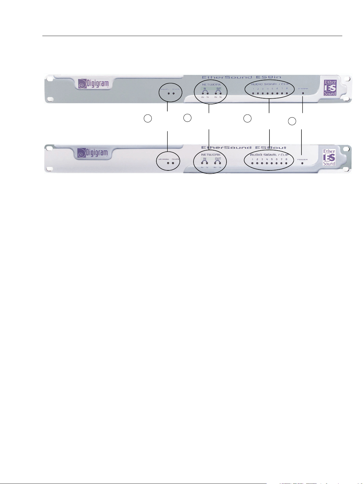
The ES8in/ES8mic and ES8out front panels
1
Device status
group
2
Network status
group
Audio metering
3
group
4
Power
1. Device status group (two orange LEDs):
on ES8in/ES8mic
The first LED is called “Primary”. It shines when ES8in/ES8mic is the first Master device in the EtherSound
network, thus the Primary Master of the EtherSound network (see chapter on EtherSound for more details on
the Primary Master concept)
on ES8out
The first LED is called “Upstream”. It indicates that an EtherSound stream is correctly received on the “IN”
(“FROM”) port of ES8out; in normal operation mode it constantly emits light, unless the connections to the
network have not been properly established.
on all ES8 devices
The second LED is labeled “Remote” on all devices: It is lightened when the EtherSound channel configuration
is done remotely and not by the rotary switches on the rear panels.
2. Network status group
These four green LEDs indicate an activity on the two Ethernet ports (“IN” (“FROM”) and “OUT” (“TO”)); RX
flashing means that data are received while TX flashing means that data are transmitted. As the audio in the
EtherSound stream is unidirectional (from the “IN” (“FROM”) port to the “OUT” (“TO”) port), the RX of “IN”
(“FROM”) and the TX of “OUT” (“TO”) will flash most of the time during normal operation. The TX of “IN”
(“FROM”) and the RX of “OUT” (“TO”) will flash more rarely as they only concern control data (which is bidirectional on the EtherSound network).
3. Audio metering group
These eight bi-color LEDs exemplify the level of the analog signals passing into the eight channels of the
device. They change from green to red at 6 dB before clipping (i.e. “-6 dBfs”).
4. Power
This LED simply shows that the device is up and running!
5
D i g i g r a m
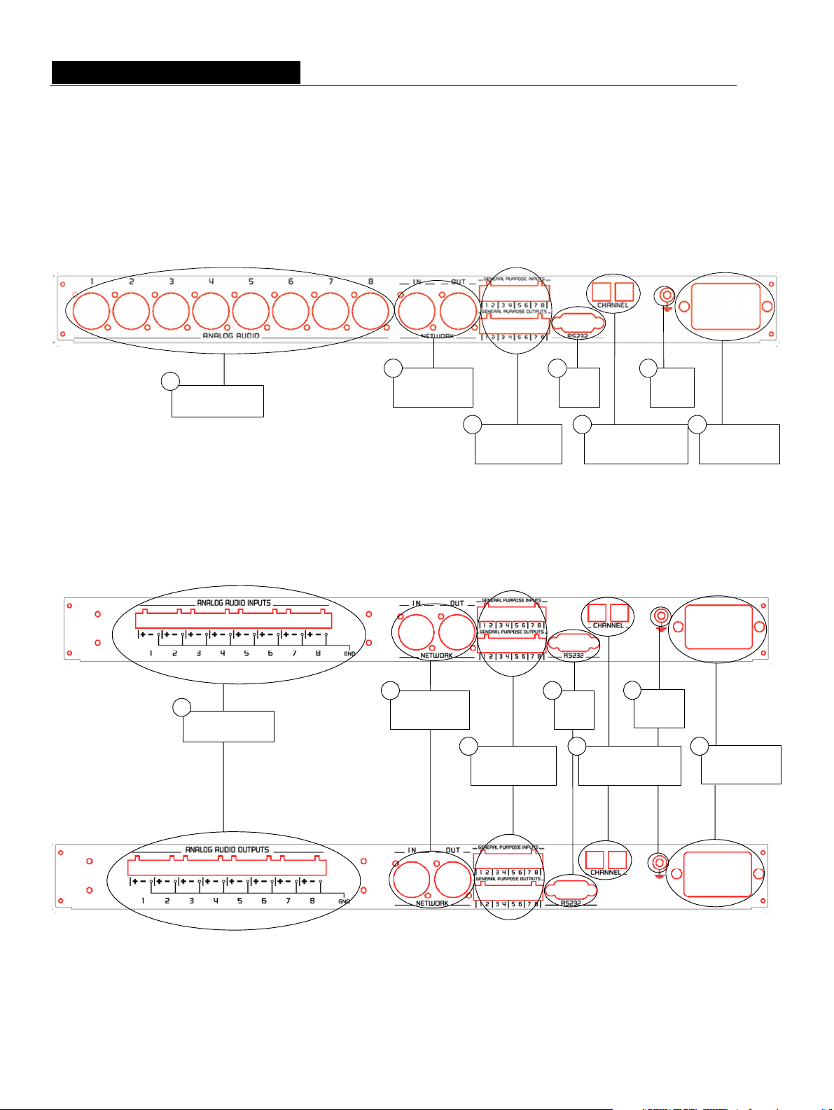
The ES8in/ES8mic and ES8out rear panels
XLR models
1
Audio connectors
Terminal block models
1
Audio connectors
2
connectors
2
connectors
Network
Network
3
3
GPIO
connectors
GPIO
connectors
4
Serial
port
5
EtherSound channel
4
Serial
port
5
EtherSound channel
6
positionning
6
Ground
positioning
Ground
7
Power supply
7
Power supply
6

EtherSound ES8in, ES8mic & ES8out
Ethernet Audio Bridges
1. Audio connectors
On ES8out XLR, eight male XLR-3 connectors are used to output eight balanced analog line level
signals; on ES8in XLR, eight female XLR-3 connectors are used to input eight balanced analog line
level signals, on ES8mic the input signals can be either microphone or line level. As the distinction
between in/out using female/male convention is not possible with Terminal Block models, the
serigraphy recalls whether these are inputs or outputs. Counterparts are supplied to facilitate the use
of the terminal blocks but you may buy different models at your convenience through your usual
electric parts reseller.
2. Network connectors
These two Neutrik
EtherSound network. The “IN” (“FROM”) port receives the EtherSound stream (from devices located
“upstream”) while the “OUT” (“TO”) port forwards it to the next devices (located “downstream”); see
EtherSound chapter for more details on upstream/downstream concepts.
3. GPIO connectors
These terminal blocks allow setup of external control and monitoring devices through configurable
and protected General Purpose Inputs and Outputs. See dedicated GPIO chapter for details.
Note: The GPIO ports are managed by configuration software only.
4. Serial port
RS232 interface on DB9.
Note: The RS232 serial port management requires specific software.
5. EtherSound channel positioning
These two decimal rotary switches determine whether the assignment of the EtherSound channels to
the analog inputs or outputs of ES8 is done locally or remotely through software control.
6. Ground
Connect this ground bolt to the chassis of the mounting rack for a better grounding of the electronics,
thus ensuring immunity to electromagnetic interference.
7. Power supply
Power plug MUST be earthed properly.
TM
EtherConTM RJ45 connectors allow of a steady and reliable connection to the
7

D i g i g r a m
INSTALLATION
Note: To use your ES8 devices outside of fixed installations, they must be mounted on slide rails inside the rack to
insure correct support and prevent damages during transport and handling.
Before mounting devices in a rack…
Internal settings (ES8in/ES8mic only)
On ES8in, impedance and the nominal level of entry, as well as the sampling rate can be configured using
internal jumpers.
On ES8mic, only the sampling rate is configurable.
The default values are:
- Nominal input level: +4 dBu
- Impedance: 22.2kΩ
- Sampling frequency: 48 kHz.
In case you need to change the default settings, please refer to appendix B of this manual.
Note: These operations require opening of the cabinet and shall be done by qualified personnel only.
Connecting your EtherSound device
It is recommended to establish all connections before powering up the device.
Power
Before plugging the power cord, make sure that:
• the power cord is not damaged
• the AC outlet used is properly earthed.
Just like any other audio system, power the individual devices up following the audio path and power down
in the opposite direction.
Do not allow anything to rest on the power cable. Keep the power cable away from where people could trip
over it.
Network
The cable type most commonly used today is CAT5e. For more detailed information, please refer to the
chapter “Ethernet cables” in this manual.
The network connections are established via two Neutrik
Connection is very easy: use the base labeled “IN” (“FROM”) to input the EtherSound stream,
the base labeled “OUT” (“TO”) to send the EtherSound stream to other devices.
The Neutrik
disconnect the cable from the device, press the latch, then withdraw the cable while
maintaining the latch pushed.
If you use ES8in/ES8mic as the Primary Master, the “IN” (“FROM”) port may be connected directly to a
control computer for system configuration with a crossover cable
standard cables are to be used.
TM
EtherConTM RJ45 provide secure connection through a latching system. To
TM
EtherConTM RJ45 receptacles.
; if connection is established via a switch,
Example 1: point-to-point transmission of eight audio channels
This application is very easy with EtherSound ES8in/ES8mic and ES8out.
8
EtherSound ES8in, ES8mic & ES8out
Ethernet Audio Bridges
Connect a standard Ethernet cable between an ES8in/ES8mic “OUT” (“TO”) port to the “IN” (“FROM”) port of
an ES8out device. Select the ES8in/ES8mic and ES8out channels accordingly (see “Setting the EtherSound
channels” chapter).
Example 2: adding more devices
You can easily insert further ES8 devices to build a simple daisy chain. There are only two rules to follow:
1. The first device in the chain is necessarily the Primary Master, typically an ES8in/ES8mic.
2. Install the devices in the chain starting from the Primary Master; connect its “OUT” (“TO”) port to the
“IN” (“FROM”) port of the next device, connect its “OUT” (“TO”) port to the “IN” (“FROM”) port of
the following device, and so on.
Example 3: more complex architectures
System topology may be daisy chain, star, or a combination of both. The first device in a network, such as an
EtherSound ES8in/ES8mic, provides the master clock for the entire network.
Connect the one device's “OUT” (“TO”) port to the “IN” (“FROM”) port of the following device (EtherSound
ES8in/ES8mic for inserting additional channels or EtherSound ES8out for extracting existing channels).
Repeat this step for each device in the network. The maximum distance between two devices is 100 meters
(328 feet). Intermediate switches or fiber optic links may be used to considerably increase this distance.
All EtherSound devices “downstream” from an audio source can play the corresponding network channel.
Connecting a computer to manage the EtherSound network
To connect a PC directly to ES8in/ES8mic, it must be equipped with a network card. Use a
crossover Ethernet cable
Primary Master.
You can also access the Primary Master through a conventional Ethernet network; in this case, use a standard
Ethernet cable (e. g. connected to a switch)
to connect the network card to the “IN” (“FROM”) port of the
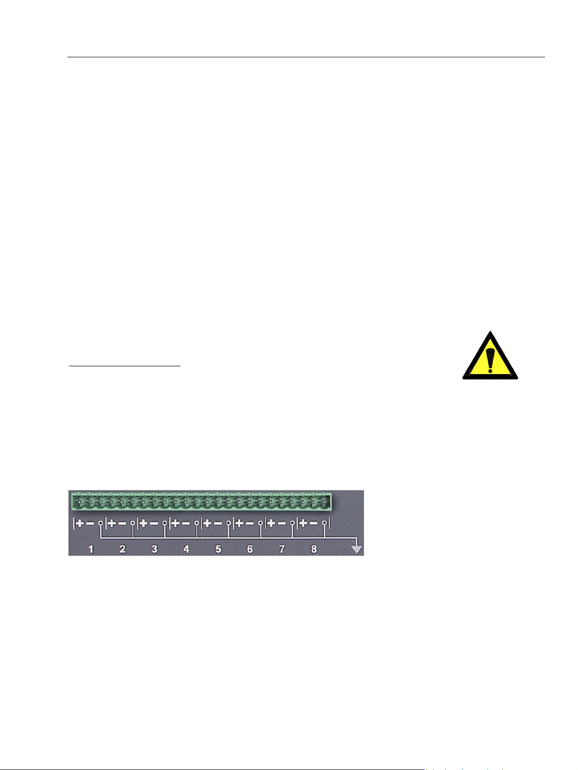
Audio
Depending on the ES8 model purchased, balanced inputs and outputs are available either on eight XLRs or on
a terminal block on the rear panel. The pinout used on the XLRs is standard: pin 1 carries the signal ground,
pin 2 carries the positive signal (“hot”, +) and pin 3 carries the negative signal (“cold”, -).
The pinout of the terminal block is depicted beneath the strip:
These balanced connections are
compatible with unbalanced audio
sources and destinations: just wire
both cold pin and ground pin on ES8
to the ground of the unbalanced signal,
and the ES8 hot pin to the signal.
By default, ES8in/ES8mic nominal input level is set to +4 dBu; for details, see Appendix B.
By default, ES8out nominal output level is +4 dBu. The value can be adjusted for each channel through
management software and stored in the ES8out device.
GPIO
ES8in/ES8mic and ES8out are shipped with four GPIs and four GPOs on terminal blocks, counterparts are
supplied. For details see Appendix A.
9
D i g i g r a m
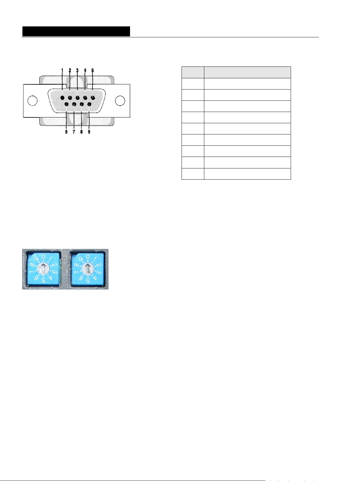
Serial port (RS232 on DB9)
ES8in/ES8mic and ES8out dispose of a serial RS232 DB9 male port on the rear panel. Use this port to connect
any compatible device. For pinout allocation details, please refer to the figure and table above.
Note: The RS232 serial port requires specific software.
Pin # Description
1 not connected
2 RxD (received data)
3 TxD (transmitted data)
4 not connected
5 signal ground
6 not connected
7 RTS (request to send)
8 CTS (clear to send)
9 not connected
Setting the EtherSound channels
These two decimal rotary switches on the rear panel determine whether the
assignment of the EtherSound channels to the analog inputs or outputs of
ES8 is done locally or remotely by software control. The rotary switch on
the left is the “tens” position and the rotary switch on the right is the “ones”
position. Channels 1 to 64 are reserved for manual set-up, 0 and the
channels from 65 on set the device to remote configuration mode.
Manual set-up
To manually set the EtherSound channels to be used by the device, configure the number of the EtherSound
channel to be assigned to the first analog input or output using a small screwdriver (e. g. if you choose
channel no. 24 to be the first EtherSound channel, set the left switch to “2”, the right one to “4”). The other
channels will then be assigned subsequently (e. g. second channel = 25, third channel = 26 and so on…).
10

EtherSound ES8in, ES8mic & ES8out
Ethernet Audio Bridges
ES8mic & ES8micCL management
The ES8mic & ES8micCL management requires connection to a PC and Digigram's EScontrol software. For
further information, please refer to the EScontrol online help.
Remote set-up by means of configuration software
To prepare the device for remote control mode, set the rotary switches manually to either zero or to any
number between 65 and 99. Use of the configuration software allows for advanced channel allocation; for
software details, please refer to the online help file.
ES8in/ES8mic is shipped with a CD-ROM containing it’s the driver and EScontrol, the Digigram configuration
software. Insert the CD into a computer connected to an EtherSound network. Install the EtherSound driver
first. A window lists the instructions to follow to achieve this step.
Next, launch EScontrol setup.exe. An InstallShield Wizard will guide you through the installation process.
(Note: This operation is only necessary if software control is needed).
ES8in/ES8mic and ES8out may also be managed through configuration software edited by Digigram
development partners.
To uninstall the software go to Add/remove programs in the Windows Control Panel.
Firmware update
Digigram may decide in the context of further development to provide firmware updates for existing devices.
In this case, please refer to the respective documentation provided with the firmware upgrade tool.
11

D i g i g r a m
SPECIFICATIONS
Configuration
Size 1U 19“ rack: 43.9 x 482.6 x 297.1 mm
Power supply 100 – 240 VAC, 47-400 Hz
switching-mode, automatic voltage detection
WARNING: Do not open the power supply module. It contains hazardous
voltages. There are no user-serviceable parts inside
Temperature/humidity
(non-condensing):
Operating:
Storage:
Power consumption 0.29 A
Net weight
0 °C – 50 °C / 0% - 95%
-5 °C – 70 °C / 0% - 95%
∼3,4 kg (∼7.5 lbs)
Parameters
Selection of audio channels Manually by rotary switches or by Windows 2000/XP compatible software
EtherSound System
Configuration Software
Software application allowing the detection of the EtherSound network,
remote channel assignment, control of the GPIOs
Inputs/Outputs
EtherSound ES8in EtherSound ES8mic EtherSound ES8out
Analog audio
Impedance
8 balanced analog mono
line inputs
22.2 kΩ 22.2 kΩ <100 Ω
8 balanced analog mono
line/mic inputs
with switchable
48 V phantom power
8 servo-balanced
mono line outputs
∗
analog
Nominal level +4 dBu or -10 dBV
(switchable)
Maximum level
Analog output gain
+22 dBu or +10 dBu
(switchable)
-62, -44, -26, -8, +4 dBu
(software selectable)
line: +22 dBu
mic: +10 dBu
(software selectable)
+4 dBu
(software adjustable)
+22 dBu
(software adjustable)
from –72 to 0 dB
(software adjustable)
ES8micCL special features
Programmable noise-gate threshold -52 dB, -42 dB, -32 dB
Programmable compressor/limiter threshold From –26 dB to 0 dB
Programmable compressor ratio 1, 1.5, 1.8, 2, 3, 4
Programmable compressor/limiter gain From 0 to 16 dB
∗
Electronically servo-balanced outputs provide automatic level adjustment to accommodate either balanced or unbalanced lines
12
 Loading...