

digigard DG85 Programming Manual
Outdoor High-Security Digital Motion Detector Modules
DG85
OPERATIONAL MODE
Digigard DG85 can function in two operational modes (see Table 4 below): DGP2 Mode or Relay Mode. When set to Relay Mode, DG85 functions as would
any standard motion detector by communicating its alarm and tamper signals via relays. When set to DGP2 Mode, DG85 functions like a DGP2 motion
detector module by communicating alarm signals, tamper signals, data and detector settings via the combus. In DGP2 Mode, both section programming and
manual programming can be used to program the settings. In Relay Mode, only manual programming can be used to program the settings (see Table 4
below). Refer to DG85’s connection drawing on page 33 for the location of the DIP switches.
DIP Switch 1:OFF = Relay Mode (default)
ON = DGP2 Mode
SETTINGS
Refer to DG85’s connection drawing on page 33 for the location of the DIP switches and Trimpot.
Table 4: DG85 Settings
Feature Setting
Section Programming
Signal Processing Mode
LED
Movement Signal Indication
Tamper Recognition
Sensitivity
3
Single [001]J[1] = OFF DIP switch 2 = OFF
Dual
U
Disabled [001]J[2] = OFF DIP switch 3 = OFF
Enabled
Disabled [001]J[3] = OFF
Enabled
Disabled U
Enabled [001]J[5] = ON N/A
U
U
U = 10 seconds
[001]J[1] = ON DIP switch 2 = ON
[001]J[2] = ON DIP switch 3 = ON
[001]J[3] = ON
[001]J[5] = OFF N/A
[002]J001-010
U Default Setting
1
When in DGP2 Mode only (see Operational Mode above).
2
When in DGP2 Mode or Relay Mode (see Operational Mode above).
3
This feature is always enabled in Relay Mode.
4
To set the sensitivity manually, remove the front cover and, using a screwdriver, turn the trimpot clockwise to increase the detector’s sensitivity or
counter-clockwise to decrease it. You can turn the trimpot 360° in both directions. To determine the sensitivity setting, remove the cover and view how
many times the LED flashes. The number of times the LED flashes corresponds to the sensitivity setting. Thus if the sensitivity is set to 6, the LED will flash
6 times.
In instances where a particular setting can be set either manually or through section programming, a discrepancy may exist between the
setting of the DIP switches and the setting in the appropriate sections. In such cases, the last change that is made will dictate the setting.
For example, if you disable the LED from within section programming, the DIP switch will still show that it is enabled, however the LED is
actually disabled.
Digiplex & DigiplexNE - 11 - Modules Programming Guide
Programming
1
Manual Settings
Enabled when DIP switch 3 = ON
TrimpotJ0-10
4
2
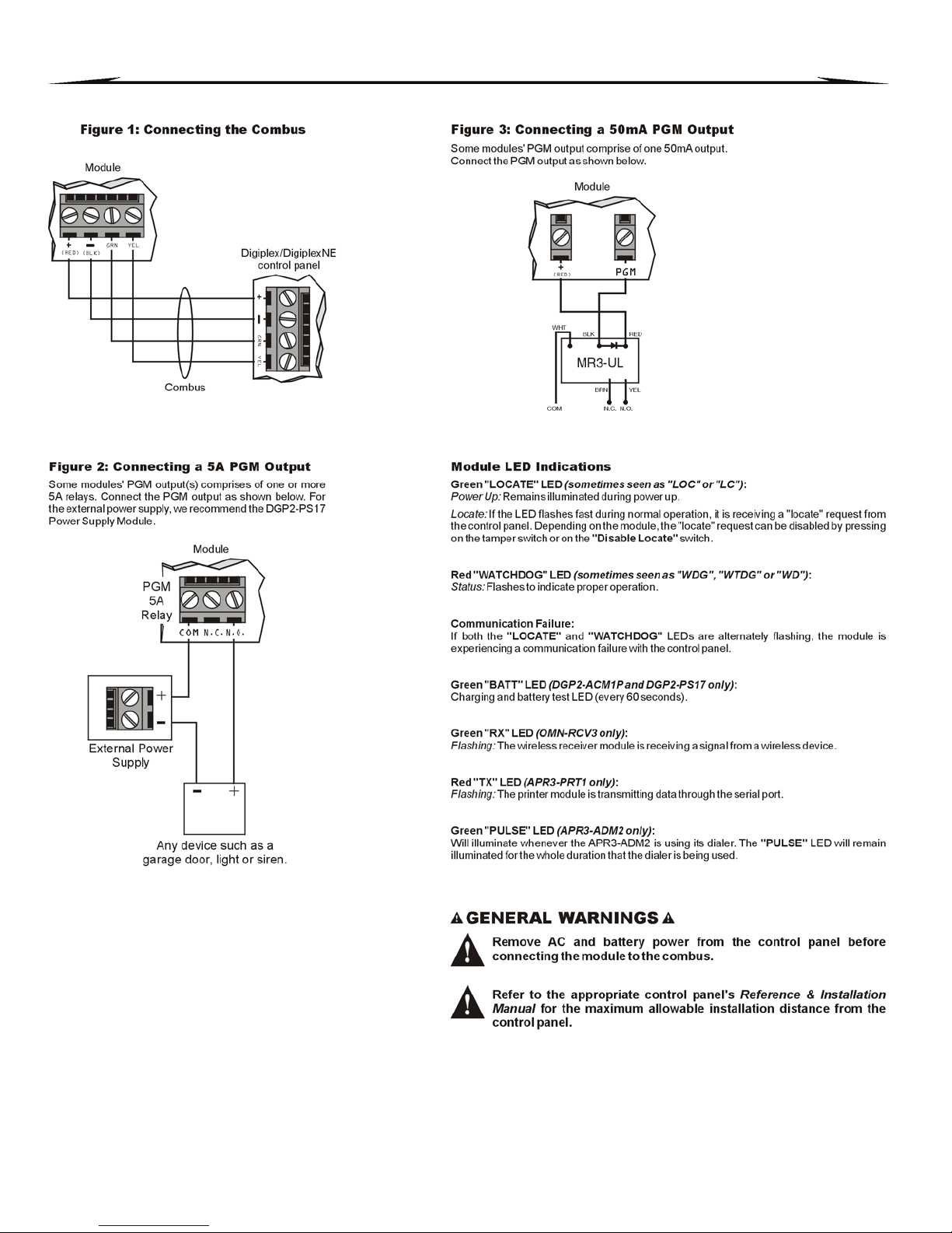
Module Connection Drawings
MODULE CONNECTION OVERVIEW
Digiplex & DigiplexNE - 29 - Modules Programming Guide
 Loading...