

Page 1
User
Guide
Issue 1.02
VISION-64
Security Controller
®
Page 2

2
Vision-64 User Guide
VISION-64
Security Controller
Document Part Number MACC110U
Document Issue 1.02
Date Released 10 November 2004
Firmware Revision 0.117 or higher
Hardware Revision D or higher
VisionLink version required
COPYRIGHT NOTICE
Copyright © 2002-2004 by Digiflex Pty Limited, Sydney, Australia
All rights reserved. No part of this publication may be reproduced,
transmitted or stored in a retrieval system in any form or by
any means, electronic, mechanical, photocopying, recording, or
otherwise, without the prior written permission of Digiflex Pty
Limited.
TRADEMARKS
Throughout this document trademark names may have been used.
Rather than put a trademark symbol in every occurrence of a
trademark name, we state that we are using the names only in an
editorial fashion and to the benefit of the trademark owner with no
intention of infringement of the trademark.
NOTICE OF LIABILITY
While every effort has been taken the accuracy of this document,
neither Digiflex Pty Limited nor any of its official representatives
shall have any liability to any person or entity with respect to any
liability, loss or damage caused or alleged to be caused directly or
indirectly by the information contained in this book. Should you
find any error on inconsistency, please notify us accordingly.
Digiflex Pty Limited reserves the right to make changes to features
and specifications at any time without prior notification in the
interest of ongoing product development and improvement.
V1.00 or higher
TELEPERMIT NOTE
The grant of a Telepermit for a device in no way indicates Telecom
acceptance of responsibility for the correct operation of that device
under all operating conditions.
This equipment shall not be used in any manner that could constitute
a nuisance to other Telecom customers.
Immediately disconnect this equipment should it become physically
damaged, and arrange for its disposal or repair.
The transmit level from this device is set as a fixed level and because
of this there may be circumstances where the performance is less
than optimal. Before reporting such occurrences as faults, please
check the line with a standard telepermitted telephone.
Warnings
1) This product must be installed by a qualified and licensed
security installer.
2) This product may not perform as expected if installed
incorrectly.
3) Some features of this product require a working telephone
line to operate and telephone communication service
provider charges may be applicable.
4) Australian standard AS 2201 require regular service by
qualified and licensed security persons and regular user
testing. Please consult your security alarm company for
further details.
5) Incorrect programming of options can result in operation
contrary to what may be desired.
6) Leave the mains adapter plugged in at all times.
7) Leave the telephone line plugged in at all times under normal
conditions.
Issue 1.02
Copyright
© 2002-2004 Digflex Pty Ltd
Page 3

Cont e n t s
Vision-64 User Guide
3
Copyright Notice ......................................................... 2
Trademarks .................................................................. 2
Notice of Liability ........................................................ 2
Telepermit Note .......................................................... 2
Program Menu Tree ......................................................... 4
Introduction ...................................................................... 5
Features ............................................................................ 5
User’s Guide ..................................................................... 5
Reporting Alarms ............................................................. 6
About the Keypad ............................................................ 6
Keypad Keys ................................................................ 6
Status Icons / LED’s ..................................................... 6
Keypad Tones ............................................................... 7
Basic System Operation ................................................... 8
Turning An Area All On .............................................. 8
Turning An Area Part On / Part 2 On ......................... 8
Turning The System Off .............................................. 8
Silencing Alarms .......................................................... 8
Automatic Arming ...................................................... 8
System Programming ....................................................... 9
Change Own PIN ..................................................... 9
Programming Text Using The Keypad ........................ 9
Change Other PIN ................................................. 10
Add PIN .................................................................. 10
Delete PIN .............................................................. 10
Tokens ........................................................................ 11
Add Token .............................................................. 11
Delete Token .......................................................... 11
Token Status ........................................................... 11
RF Keyfob .................................................................. 11
Add Keyfob ............................................................. 11
Delete Keyfob ......................................................... 12
User Name ............................................................. 12
Area Assignment .................................................... 12
User Options .......................................................... 12
Timer Group ........................................................... 13
Access Assignment ................................................. 13
Areas .......................................................................... 13
Area Status ............................................................ 13
Turn Area On/Off ................................................... 14
Turn All Areas On .................................................. 14
Turn All Areas Off .................................................. 14
Move To Area ......................................................... 14
Chime On/Off ......................................................... 14
Area Name ............................................................. 15
Inputs ......................................................................... 15
Zone Status ............................................................ 15
Bypass Zones .......................................................... 15
Set Chime Zones .................................................... 16
Set Part 2 Zones .................................................... 16
Smoke Sensor Reset .............................................. 17
Zone Name ............................................................ 17
Walk Test All Zones ................................................ 17
Walk Test A Single Zone ........................................ 17
Outputs ...................................................................... 18
Output Status ........................................................ 18
Turn Output On/Off ............................................... 18
Output Name ......................................................... 18
External Siren Test ................................................. 19
Internal Siren Test .................................................. 19
Strobe Test ............................................................. 19
Communication / Reporting ......................................
20
Call/Answer RAS .................................................... 20
Call Forward On/Off ............................................... 20
Check Web Email ................................................... 20
Email System Log ................................................... 20
Set Domestic Phone Number ............................... 20
Call Forward On Number ...................................... 21
Call Forward Off Number ...................................... 21
Customer ................................................................ 21
Send Test Report .................................................... 21
Devices and Optional Modules ................................. 22
Keypad Status ........................................................ 22
RF Status ................................................................ 22
Serial Status ........................................................... 22
X10 Status .............................................................. 22
LAN P/Supply ......................................................... 22
GSM Status ............................................................ 22
Ethernet Status ...................................................... 22
Access Status ......................................................... 23
X10 Status .............................................................. 23
Volume .................................................................... 23
Contrast .................................................................. 23
Backlight ................................................................. 23
System Events ........................................................... 23
Panel Status ............................................................ 23
System Trouble ....................................................... 23
History Log ............................................................. 24
Set Date & Time .................................................... 24
Name ...................................................................... 26
Time ........................................................................ 26
Day .......................................................................... 26
Name ...................................................................... 26
Start / Stop Day ..................................................... 27
Keypad Hi/Lo Temp ................................................ 27
Walk Test All Zones ................................................ 27
Battery Test ............................................................ 28
Installation Details .......................................................... 29
Index ............................................................................... 30
Issue 1.02
Copyright
© 2002-2004 Digflex Pty Ltd
Page 4

4
Vision-64 User Guide
Prog ram Men u T r e e
Table 1: shows all of the system options in a tabular format. Each option can be access by pressing the Menu key and then drilling down
using the arrow and OK keys until the required option is listed on the display. A quick way to jump to a particular option is to press the
Menu key followed by the specific option number.
You may be asked to enter your PIN when accessing some options.
Example:
To set a new call forward number enter MENU + 5 + 1 + 6 and then follow the on screen prompts.
1 Access 2 Areas 3 Inputs 4 Outputs
1-0 Commands 2-0 Commands 3-0 Command 4-0 Commands
1-0-0 Erase User 2-0-0 Area Status 3-0-0 Zone Status 4-0-0 Output Status
1-1 PIN Codes 2-0-2 Turn All Areas On 3-0-3 Set Chime Zones
1-1-0 Change Own PIN 2-0-3 Turn All Areas Off 3-0-4 Set Part 2 Zones 4-1 Output Properties
1-1-1 Change Other PIN 2-0-4 Move To Area 3-0-5 Smoke Sensor Reset 4-1-0 Output Name
1-1-2 Add PIN 2-0-5 Chime On/Off
1-1-3 Delete PIN 3-1 Zone Properties 4-9 Output Testing
1-2 Token 2-1-0 Area Name 4-9-1 Internal Siren Test
1-2-0 Add Token 3-9 Input Testing 4-9-2 Strobe Test
1-2-1 Delete Token 3-9-0 Walk Test All Zones
1-2-2 Token Status 3-9-1 Walk Test A Zone
2-0-1 Turn Area On/Off 3-0-2 Bypass Zones 4-0-1 Turn Output On/Off
2-1 Area Properties 3-1-0 Zone Name 4-9-0 External Siren Test
1-3 RF Keyfob
1-3-0 Add Keyfob
1-3-1 Delete Keyfob
1-4 User Properties
1-4-0 User Name
1-4-1 Area Assignment
1-4-2 User Options
1-4-4 Timer Group
1-4-5 Access Assignment
5 Comms 6 Devices 7 System
5-0 Commands 6-0 Commands 7-0 Commands
5-0-0 Set Domestic Number 6-0-0 Keypad Status 7-0-0 Panel Status
5-0-1 Call/Answer RAS 6-0-1 RF Status 7-0-1 System Trouble
5-0-2 Call Forward On/Off 6-0-2 Serial Status 7-0-2 History Log
5-0-3 Check Web Email 6-0-3 Output Status
5-0-4 Email System Log 6-0-4 LAN P/Supply Status 7-1 Clock
5-1 Telephone Numbers 6-0-6 Ethernet Status
5-1-5 Domestic Number 6-0-7 Access Status 7-5 Schedules (TEF)
5-1-6 Call Forward On 6-0-8 X10 Status 7-5-0 Name
5-1-7 Call Forward Off 7-5-1 Time
5-5 Registration 6-1-0 Volume 7-5-3 Function
5-5-0 Customer 6-1-1 Contrast
5-9 Periodic Test 7-6-0 Name
5-9-0 Send Test Report 7-6-1 Start Stop Dates
6-0-5 GSM Status 7-1-0 Set Date & Time
6-1 Keypads 7-5-2 Day
6-1-2 Backlight 7-6 Holidays
Issue 1.02
7-7 System Options
7-7-3 Keypad Hi/Lo Temp
7-9 System Testing
7-9-0 Walk Test All Zones
7-9-1 Battery Test
Table 1: Vision-64 Menu Tree
Copyright
© 2002-2004 Digflex Pty Ltd
Page 5
Intr o d u c t i o n
Your system helps to secure life, property and investments against
fire, theft and bodily harm. It consists of a keypad (or keypads),
sensors such as motion detectors or devices located on doors
and windows, and other sensing devices designed to detect the
presence of smoke or combustion. The location and quantity of
sensing devices will have already been discussed with you by your
alarm installer.
Control of your security system is achieved through the unique
Vision Graphic keypad, which displays all system information
in written text and graphical symbols. Its versatility and ease of
operation, make it ideal for any home or business application.
Fe at u r e s
Listed below are the main features of the VISION-64 control
panel.
Up to 64 Fully Programmable Zones
Fire Alarm Verification
Up to 48 Unique PINs
Up to 5 Relay Outputs (1 amp rating)
3 Open Collector Outputs
Supervised Siren Driver
8 Programmable Schedules
Up To 8 Areas (Common Area Programmable)
Built-In Dialler
Up To 8 Fully Supervised Graphic Keypads
Keyswitch Input (Programmable)
256 History Event Memory
EMI / Lightning Transient Protection
Programmable Via Keypad
Remote Programmable Via Upload/Download Software
Alarm Event Memory
Automatic Test Reports
Built-In Telephone Line Fail Monitor
Securitel Compatible
User ’ s G u i d e
This user’s guide shows you how to use and maintain your security
system. It covers basic functions, such as turning the system on
and off as well as some general programming. More complex
programming and system configuration should be performed by
your installer.
Many of the programming functions described in this guide will have
already been programmed by your alarm installer while others may
need to be programmed or changed by you. Depending on your
particular system configuration some features described in this
manual may not be available. Please discuss this with your alarm
installer.
Functions outlined in this user guide may require you to enter your
PIN (Personal Identification Number) so make sure you choose a
number that is easy to remember. For security reasons do not write
this code down or give it to anyone else. If more than one person
needs to operate the system then you should create a unique code
for them if this has not been done by your installer. This guide will
explain how to do this.
Please take the time to familiarise your self with the following terms
before reading the rest of this guide.
Zones
A ‘Zone’ is a detection device, or group of devices connected
to your security system. Zones are identified by the area they
monitor, such as a front door, bedroom window or hallway.
Vision-64 User Guide
5
Faulted Zones
When a zone (such as a door or window) is closed, it is said to be
‘normal’. When the door or window is open, the zone is said to be
‘faulted’. When you turn your system on, you will usually want all
of the zones in your system to be normal, although, you can turn
your system on with faulted zones.
Zones Types
There are two basic types of zones, Non 24-hour and 24-hour.
See below.
Non 24-Hour Zones
Non 24-hour zones respond to alarm conditions depending upon
whether the system is turned on or off. They are programmed to
either respond instantly to alarm conditions or to provide a delay
for you to reach the keypad and turn the system off. Various zones
will be located throughout your premises.
When you turn your system on, you have the option of turning on
all zones (All On), or just some of the zones (Part On). Refer to
All On and Part On, on page 7 for more information.
Bypassed Zones
A zone which has been bypassed will remain unarmed when the
system is armed. You may need to bypass a zone when doing
renovations in the building or if a sensor becomes faulty. Bypassed
zones will reset the next time the system is disarmed.
24-Hour Zones
24-hour zones are always on and cannot be turned off, even when
the system is turned off (disarmed). There are two types of 24hour zones, fire zones and non-fire zones.
What Is An Area?
The Vision control panel comes defaulted and programmed for a
single area configuration (Area 1), therefore, all zones are assigned
to Area 1. The alarm system can be divided into 4 individual areas
running off the same Vision control panel. In this case, the security
company would assign different sensors (zones) to each area
according to the area they belong.
Example:
Partitioning a commercial business to 4 individual areas may be as
follows:
Area 1 – Main entry/exit area
Area 2 – Sales
Area 3 – Administration
Area 4 – Dispatch
Each area can be controlled individually as if they were separate
alarm systems.
All On
When you turn an area All On, you are turning on all non 24-hour
zones, both interior (motion detectors) and perimeter (doors and
windows of the building).
Part On
When you turn an area Part On, you only turn on some of the
non 24-hour zones. Your security company will program which
zones are included in this portion. Part zones may include only
the perimeter (doors and windows) or your system, or sensors in
other areas of your premises. Check with your security company
to learn which zones are Part zones.
Issue 1.02
Copyright
© 2002-2004 Digflex Pty Ltd
Page 6
6
Vision-64 User Guide
Re p o rt i n g A l a r m s
Your system may be programmed to send reports to your security
company. Once the report is complete, the system returns
the telephone to normal operation (check with your security
company).
Your system makes repeated attempts to send reports to your
security company. If your system fails to report, the keypad will
display the ‘service’ symbol.
Abou t t h e Ke y pa d
Your keypad has 20 keys or buttons. The buttons allow you to
input instructions and navigate the menu screens as required. Some
buttons have a secondary function which is activated by holding
them down for two seconds.
Each button’s function is described below:
KEYPAD KEYS
Key
to
The numeric keys allow you to enter you
numbers when required
Use the [MENU] and the numeric keys to
enter commands. The [MENU] key is also
used to go back one level when navigating
through menus or to exit a programming
location without saving changes.
The [ON] key allows you to turn an area or
output on. To turn all areas on at the same
time when the system has been partitioned,
press and hold the [ON] key for two
seconds.
The [PART] key allows you to turn an area
Part On. This key can also be used to bypass
a zone or multiple zones when you press
and hold for two seconds.
The [OFF] key allows you to turn an area or
output off. To turn all areas off at the same
time when the system had been partitioned,
press and hold the [OFF] key for two
seconds.
The [OK] key allows you to save any changes
and exit the command.
Description
Key
Description
The [] key allows you to navigate through
menus or to toggle characters when
programming telephone numbers. Pressing
The [] key will display current trouble
conditions when the area that the keypad is
displaying is disarmed.
Pressing the 1 and 3 keys together and
holding them down for 2 seconds will cause
+
a Panic alarm to be triggered. If programmed
the sirens will sound and the monitoring
station will be notified.
Pressing the 4 and 6 keys together and
holding them down for 2 seconds will cause
+
a Fire alarm to be triggered. If programmed
the sirens will sound and the monitoring
station will be notified.
Pressing the 7 and 9 keys together and
holding them down for 2 seconds will
+
cause a Medical alarm to be triggered. If
programmed the sirens will sound and the
monitoring station will be notified.
Table 2: Keypad Keys and Their Function
STATUS ICONS / LED’S
The following table describes the function of each of the status
icons.
Icon Status Meaning
The keypad can display which areas (1 – 8) are turned on
or off via the Area Icon Indicators. This programmable
option can be disabled in MENU
On
Off
Flashing
Fast
On
Flashing
Flashing
The area is turned All On or Part On
The area is turned Off
The area has an alarm
System power is normal
System power is missing
A fire alarm is active
Issue 1.02
The [MAIL] key allows you to read stored
mail. This key can also be used to initiate a
dialler test when you press and hold for two
seconds.
The [] key allows you to move the cursor
left when programming text or telephone
numbers.
The [] key allows you to move the cursor
left when programming text or telephone
numbers.
The [↑] key allows you to navigate through
menus or to toggle characters when
programming telephone numbers.
Off
On
On
Off
Flashing
On
Off
No fire alarm
Fire alarm in memory
(Turn the area All On and Off to Clear).
The existing service or trouble condition
has been acknowledged.
No service or trouble conditions exist
A service or trouble condition is present
that has not been acknowledged.
The area is turned Part On.
The area is not turned Part On.
Copyright
© 2002-2004 Digflex Pty Ltd
Page 7
Vision-64 User Guide
7
Icon Status Meaning
Red
LED
Green
LED
On
Off
On
Off
On
Off
On
Off
On
Flashing
On
Flashing
The area is turned off.
The area is turned All On or Part On
The area is turned All On
The area is turned Off
You have mail waiting to be read
No Mail
Area is ready to turn on (All On / Part
On)
Not ready, Zone Open
All On
Alarm
Area is off.
Area not ready to turn on
Exit
Delay
Tone
Error
Tone
Menu
Mode
Chime
Tone
After you turn an area All On, the keypad will
sound 1 short beep every second. During the last
10 seconds fast short beeps will be heard. If you
don’t exit before the delay time expires and an
exit delay door is faulted, an alarm occurs.
If you press an incorrect key, your keypad will
sound a 2 second tone.
The keypad will sound a Hi / Lo tone to indicate
you have entered MENU Mode and a Lo/Hi tone
to indicate you have exited MENU mode.
The keypad sounds fast short beeps to alert you
when a zone programmed for chime is faulted or
unsealled.
Table 4: Keypad Tones and Their Meanings
Red &
Green
LED
Flashing
Table 3: Status ICONs, LED Indicator’s and Their Meanings
Installer programming mode is active.
KEYPAD TONES
Your keypad emits several distinct tones and displays text to
alert you to system events. Additional bells or sirens may also be
connected to your system. Bells or sirens mounted on the exterior
of your premises alert neighbours to emergencies and provide an
audible guide for police and fire fighters.
Type
Fire
Alarm
Tone
Burglary
Alarm
Tone
Trouble
Tone
When a fire zone sounds an alarm, the keypad will
sound 3 seconds on and 2 seconds off (repeat).
When a burglary zone activates while your system
is turned on, your keypad emits a continuous
siren tone. It sounds for the time set by your
security company.
When a system component is not functioning
properly, your keypad sounds 4 fast short beeps
followed by a 5 second pause (repeat).
Meaning
Figure 1: CM100 Graphic Keypad
Press
Delay
Issue 1.02
Key
Tone
Entry
Tone
Pressing any key on the keypad sounds one short
beep, indicating that the key press is accepted.
When you enter the premises through a zone
programmed for entry delay, the keypad sound a
Hi/Low tone to remind you to turn off the area.
If the area is not turned off before the entry delay
expires, an alarm condition will sound and a
report may be sent to your alarm company.
Copyright
© 2002-2004 Digflex Pty Ltd
Page 8

8
Vision-64 User Guide
Basi c S y s t e m O p e rat i o n
TURNING AN AREA ALL ON
Use this function to turn an area All On. The Vision control panel
is factory default only for one area. As soon as you turn an area
on, exit time will start. Exit time allows you to exit the premises
without sounding an alarm. Your security company programs the
length of exit delay time.
1. Make sure that all zones are normal (not faulted).
2. Enter your PIN, then press the [ON] key.
If your PIN is valid and if all zones are normal, exit delay time will
start. You should leave now. If your Vision control panel detects a
faulted zone, you should return it to normal, or bypass the zone.
During exit delay, you may stop the area from turning on by entering
your PIN followed by the [OFF] key.
3. To turn the system (or area) off, enter your PIN, then
press [OFF].
TURNING AN AREA PART ON / PART 2 ON
Use this function to turn an area Part On or Part 2 On. The Vision
control panel is factory default only for one area. Part On and Part
2 On turns on only part of the area, leaving the rest of the area
turned off.
Only the security company can program which zones are
monitored for Part On. The master user can program which zones
are monitored when a user turns an area Part 2 On.
Once you have turned an area Part On or Part 2 On, exit delay
time starts to count down. You should leave all zones that are
active before exit delay time expires. Leaving active zones after
exit delay expires causes an alarm event. Use Part On or Part 2 On
only when you want part of an area turned on.
TURNING THE SYSTEM OFF
When the system is on, you must enter through a designated entry
door to prevent an alarm. Opening a designated door (e.g. front
door) will start entry time. During entry time, the keypad will emit
a pulsing tone “beep” to remind you to turn the system off. To turn
the area off, enter your PIN followed by the [OFF] key before the
entry delay time expires.
If you enter through the wrong door or fail to turn the system off
before the entry delay time expires, you may sound an alarm. If an
alarm occurs, silence the alarm (by entering your PIN followed by
the [OFF] key) and call your security company to let them know
that it is not an emergency situation.
1. Enter your PIN + [OFF] to turn the system (or area) off.
The keypad will no longer display the ‘Lock’ or ‘Part’ icons.
SILENCING ALARMS
When the Vision control panel has registered an alarm, the keypad
(s) and sirens will sound to alert personnel that an alarm occurred.
The keypad will scroll all alarms on the keypad display for visual
feedback. If you enter your PIN before the system dials your
security company, the alarm report is cancelled (if programmed).
1. Enter your PIN + [OFF] to silence any alarm and turn the
system off.
The keypad will continue to scroll all alarm events that caused the
alarm. This is called alarm memory.
2. To clear alarm memory, turn the area on and off again (eg.
PIN + [ON] + PIN + [OFF]).
AUTOMATIC ARMING
Your system may have been programmed to automatically arm
itself at a certain time of the day.
1. Make sure that all zones are normal (not faulted).
2. Enter your PIN, then press the [PART] key.
If your PIN is valid and if all zones are normal, the keypad will
prompt you to select Part On or Part 2 On.
3. Using the arrow keys, highlight Part On or Part 2 On then
press [OK].
Exit delay time will start. You should leave now. If your system
has a faulted zone, you should return it to normal, or bypass the
faulted zone.
During exit delay, you may stop the system from turning Part On
by entering your PIN followed by the [OFF] key.
4. When exit time has expired, the keypad will display the
Part On icon.
5. To turn the system off, enter your PIN, then press [OFF].
If for some reason you are still in the building when the auto arming
is taking place then it is possible to extend or delay the auto-on
time (automatic arming time) by one hour simply by entering
your PIN during the auto-on pre-alert time. The auto-on pre-alert
time sounds the keypad buzzer to warn you that the system will
automatically turn All On, Part On or Part 2 On.
Example:
If the control panel is programmed by your installer to automatically
turn All On at 6:00pm and the auto-on pre-alert time starts beeping
the keypad at 5:55pm, entering your PIN between 5:55pm and
6:00pm will delay the auto-on time by one hour and the autoon pre-alert time will again commence at 6:55pm. Therefore the
system will automatically turn All On at 7:00pm.
Issue 1.02
Copyright
© 2002-2004 Digflex Pty Ltd
Page 9
Vision-64 User Guide
9
Syst e m P r o g ra m m i n g
Access > PIN Codes >
Change Own PIN
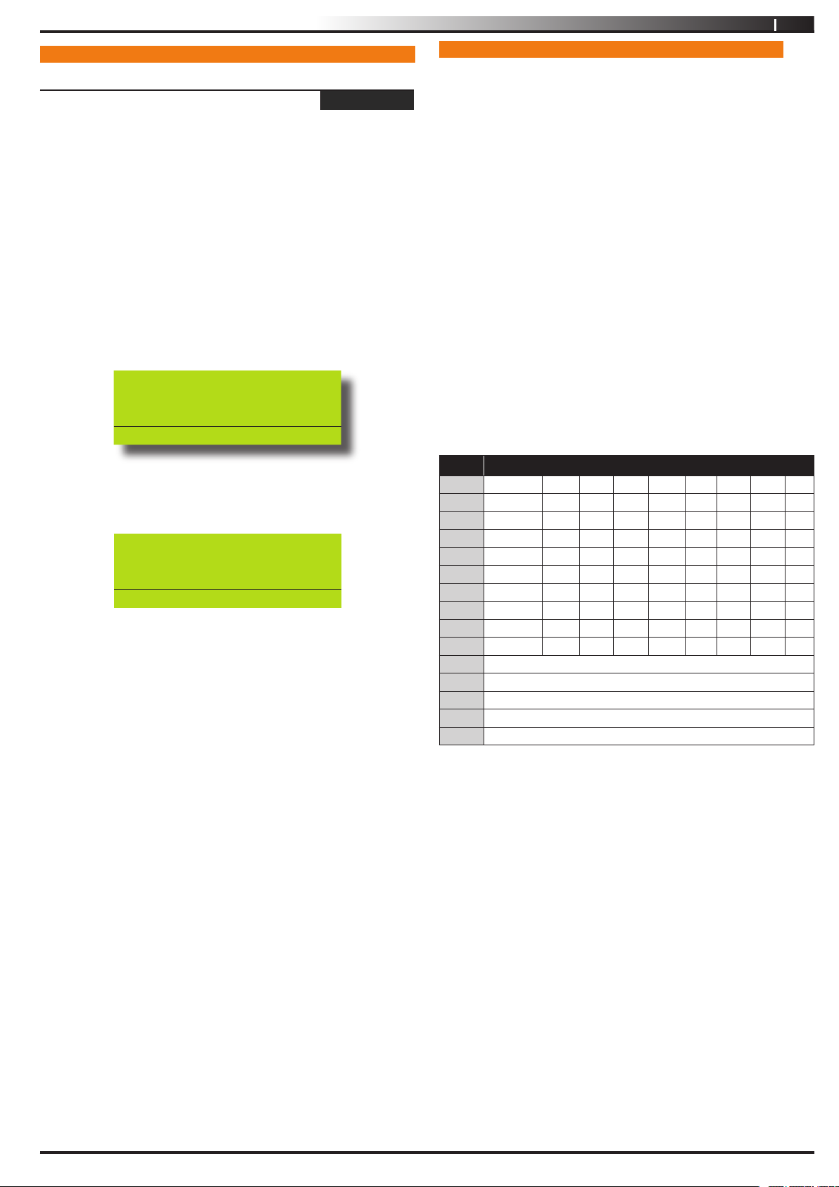
This menu lets you change your own PIN. It is recommended that
you write down your old PIN and the new one before you begin.
The new PIN must have the same number of digits as your old
PIN. Once the change is complete you should destroy the written
copy.
At factory default, each PIN is fixed to 4 digits in length. The default
PIN for User 1 (Master user) is 2580. Only the security installer
can change the PIN length.
1. Ensure that the system (or area) is turned off.
2. Enter your PIN, and then press [MENU] + [1] + [1] + [0].
The keypad will prompt you to enter a new PIN.
Enter New PIN for
DEBBIE SMITH U002
Press OK or MENU
3. Enter your new PIN, and then press [OK]. If an error tone
sounds, try a different PIN. The keypad will now prompt you
to enter your new PIN again.
Confirm New PIN for
DEBBIE SMITH U002
Press OK or MENU
4. Enter your new PIN again.
5. Press [OK] to save and exit, or press [MENU] to exit without
saving Your PIN has now been changed.
MENU 1-1-0
PROGRAMMING TEXT USING THE KEYPAD
When programming text via the keypad, various keys on the keypad
operate differently.
A group of characters is assigned to each of the numeric keys on
the keypad. Pressing the same numeric key again will toggle to
the next character assigned to the key (eg. Press the [2] key will
display the ‘A’ character, press the [2] key again will toggle to the
‘B’ character, press the [2] key again will toggle to the ‘C’ character
etc).
Once the correct character is display use the arrow keys to move
to the next letter of the word you are entering.
The key assignments are identical to those found on most fixed and
mobile phones.
When programming text, each numeric key represents a different
group of characters.
Pressing the same numeric key repeatedly will step you through
the available characters assigned to the key. The text key layout
is the same as most phones. Refer to the table below for detailed
character information.
Refer to the table below for more information.
Key Characters Assigned To Each Numeric Key
1
2
3
4
5
6
7
8
9
0
OFF
. , ? ! - & < > 1
A B C a b c 2
D E F d e f 3
G H I g h i 4
J K L j k l 5
M N O m n o 6
P Q R S p q r s 7
T U V t u v 8
W X Y Z w x y z 9
SPACE
_
@ # $ % * 0
Scroll Up through entire character list
Scroll Down through entire character list
Move to left one character position
Move to right one character position
Clear from cursor postiion to end of line
Table 4: Text Keypad Character Set
Issue 1.02
Once the desired character is displayed press the right [] arrow
key to move to the next character position.To save programming
changes, press [OK], or press [MENU] to exit without saving.
Copyright
© 2002-2004 Digflex Pty Ltd
Page 10
10
Vision-64 User Guide
Access > PIN Codes >
Change Other PIN
MENU 1-1-1
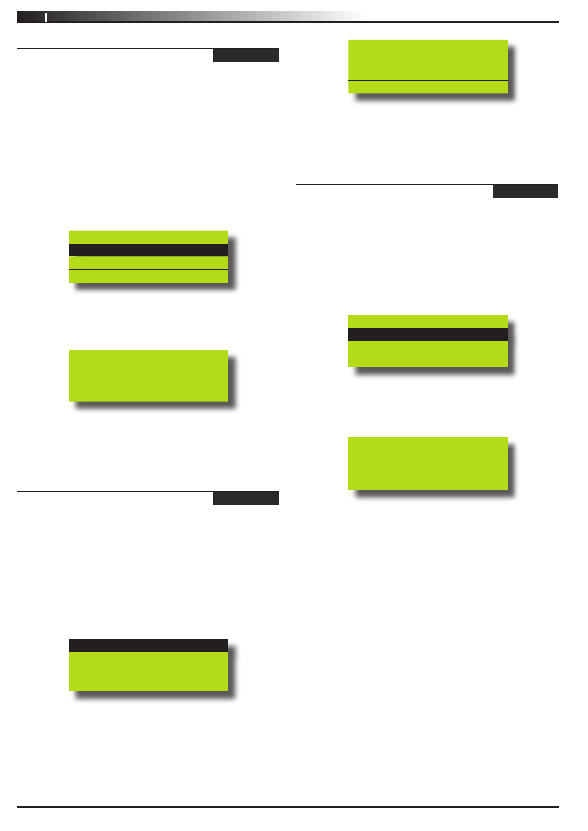
If you have a master PIN, this command allows you change
somebody ors PIN. It is recommended that you write down the
old PIN and the new one before you begin. Once the change is
complete you should destroy the written copy. The new PIN must
have the same number of digits as the old PIN.
At factory default, each PIN is fixed to 4 digits in length. The default
PIN for User 1 (Master user) is 2580.
Ensure that the system (or area) is turned off.
1.
2.
Press [MENU] + [1] + [1] + [1]. The keypad will display a
list of available users that you can change their PIN.
U001 JOHN SMITH
U002 DEBBIE SMITH
U003 USER 3 NAME
Press , OK or MENU
Use the [↑] and [↓] keys to select the user that you want to
3.
change the PIN, then press [OK] to select. Alternatively, you
can enter the user number you want to change, then press
[OK ].
Please Enter PIN for
DEBBIE SMITH U002,
Then Press OK.
Enter New PIN for
User 3 Name U003
Press OK or MENU
Enter the new PIN for the user you have selected.
3.
If an error tone sounds, try a different new PIN.
Press [OK] to save and exit, or press [MENU] to exit without
4.
saving.
Access > PIN Codes >
Delete PIN
MENU 1-1-3
This menu allows a Master user the ability delete other users PIN’s.
A Master user can only delete a PIN for those users that have been
assigned to the same area(s) as the Master user. A Master user
cannot delete their own PIN.
1. Make sure that the system is turned off.
2. Press [MENU] + [1] + [1] + [3].
The keypad will list all users that you can delete.
U001 JOHN SMITH
U002 DEBBIE SMITH
U003 USER 3 NAME
Press , OK or MENU
Enter the new PIN.
4.
If an error tone sounds, try a different PIN.
5.
Press [OK] to save and exit, or press [MENU] to exit
without saving.
Access > PIN Codes >
Add PIN
MENU 1-1-2
This menu allows a Master user to add a PIN to a new user. A
Master user can only program a new PIN for those users that have
been assigned to the same area(s) as the Master user.
At factory default, each PIN is fixed to 4 digits in length. The default
PIN for User 1 (Master user) is 2580.
Enter [MENU] + [1] + [1] + [2].
1.
A list of users will display on the keypad.
U001 JOHN SMITH
U002 DEBBIE SMITH
U003 USER 3 NAME
Press , OK or MENU
3. Use the [↑] and [↓] keys to select the user that you want to
add a PIN, then press [OK] to select. Alternatively, you can
enter the user number you want to add, then press [OK].
Press OK to delete PIN
For U002 DEBBIE SMITH
Press OK or MENU
4. Press [OK] again to delete the PIN, or press [MENU] to
cancel.
Use the [] and [↓] keys to select the user that you
2.
want to add a PIN, then press [OK] to select.
Alternatively, you can enter the user number you want
to add, then press [OK].
The keypad will prompt you to enter the new pin.
Issue 1.02
Copyright
© 2002-2004 Digflex Pty Ltd
Page 11
Vision-64 User Guide
11
TOKENS
This section outlines how to add and delete token cards that allow
an alternate method for users to turn the system on and off via a
prox reader enabled Keypad or an external reader. The system
can also be configured to automaticall open a door if it has been
fitted with an electric door lock. You should discuss this feature
with your installer for more details on your particular installation.
A token is a small plastic tag card that has a unique ID. A user can
place the token card in front of a keypad that has a built-in token
reader to turn the system or specific areas on and off.
Access > Token >
Add Token
MENU 1-2-0
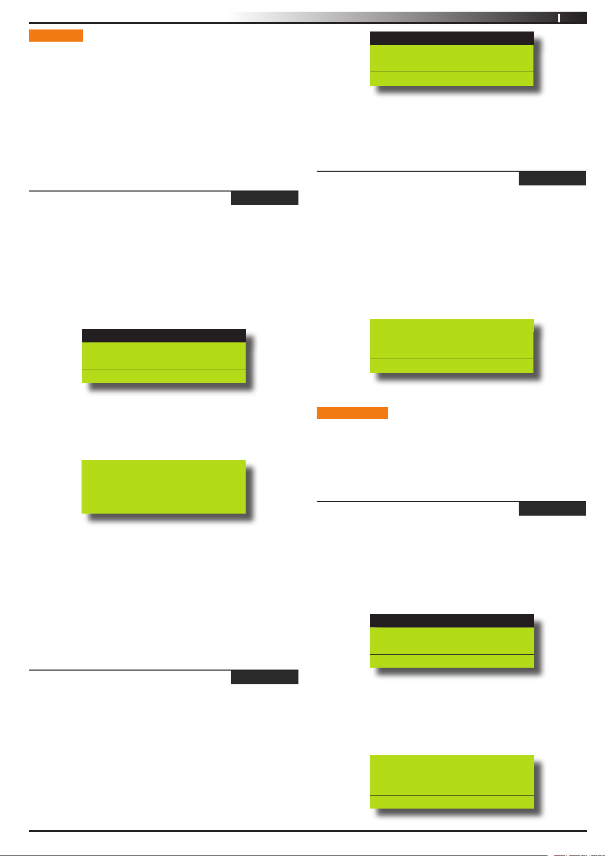
This menu allows a Master user the ability to add a new token for
for those users that have been assigned to the same area(s) as the
Master user.
1. Enter [MENU] + [1] + [2] + [0].
A list of users will display on the keypad.
Use the [] and [↓] keys to select the user that you want to
2.
add a token for, then press [OK] to select.
U001 JOHN SMITH
U002 DEBBIE SMITH
U003 USER 3 NAME
Press , OK or MENU
U001 JOHN SMITH
U002 DEBBIE SMITH
U003 USER 3 NAME
Press , OK or MENU
When prompted press the [OK] key to confirm token
3.
deletion.
Access > Token >
Token Status
MENU 1-2-2
This menu allows a Master user the ability to identify a token which
has been programmed into the system. Only tokens that have been
assigned to the same area(s) as the Master user cn be identified.
1. Enter [MENU] + [1] + [2] + [2].
The system will prompt you to present the token to the
keypad.
Once the token is presented the system will display the
2.
owner of the token.
Token belongs to ur002
DEBBIE SMITH
Press OK or MENU
If you are using a keypad with built in reader the system will
3.
prompt you to present the token to the keypad. Once the
token is presented the keypad we beep and return to the
menu.
To Add token for U001
JOHN SMITH swipe new
token
If you are learning the token via an external reader the
4.
system will prompt you to select the reader to learn from.
Use the [] and [↓] keys to select the reader and then repeat
step 3 presenting the token to the external reader.
A Master user can only delete a PIN for those users that have been
assigned to the same area(s) as the Master user. A Master user
cannot delete their own PIN.
Access > Token >
Delete Token
MENU 1-2-1
This menu allows a Master user the ability to delete a token for
those users that have been assigned to the same area(s) as the
Master user.
1. Enter [MENU] + [1] + [2] + [1].
A list of users will display on the keypad.
Use the [] and [↓] keys to select the user who’s token you
2.
want to delete, then press [OK] to select.
RF KEYFOB
This section outlines how to add and delete RF keyfobs that allow
an alternate method for users to turn an area(s) on and off. The
RF Keyfob must be compatible with the RF Receiver that has been
installed by the security company.
Access > RF Keyfob >
Add Keyfob
MENU 1-3-0
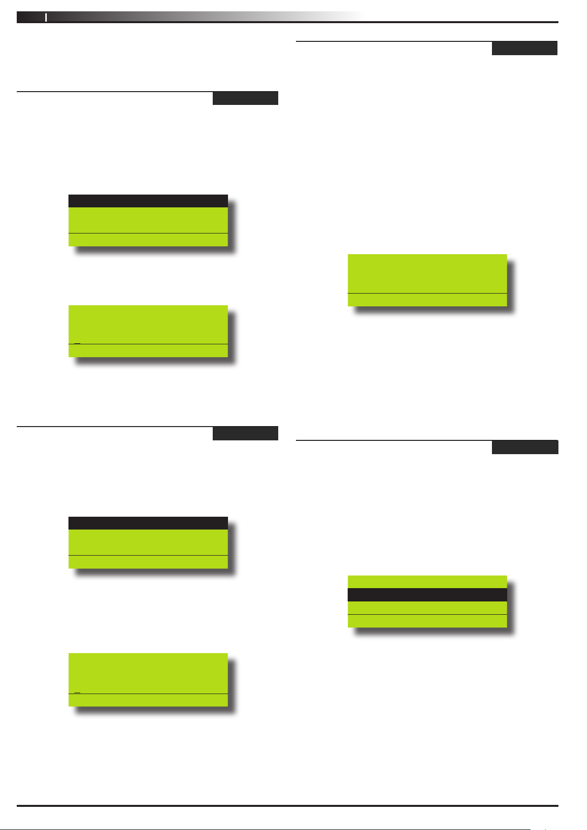
This menu allows the security installer or a master user to program
the user’s keyfob ID number.
1. Enter [MENU] + [1] + [3] + [0].
A list of users will display on the keypad.
U001 JOHN SMITH
U002 DEBBIE SMITH
U003 USER 3 NAME
PRESS , OK or MENU
2. Use the [↑] and [↓] keys to select the user that you want
to add the RF keyfob ID, then press [OK] to select.
Alternatively, you can enter the user number you, then press
[OK].
The keypad will prompt you to enter the RF keyfob ID number:
Enter keyfob RFid for
U016 User 16 Name
000000000
Press OK or MENU
Issue 1.02
Copyright
© 2002-2004 Digflex Pty Ltd
Page 12
12
3. Enter the RF Keyfob ID Number
4. Press [OK] to save and exit, or press [MENU] to exit without
Access > RF Keyfob >
Delete Keyfob
Vision-64 User Guide
saving.
MENU 1-3-1
This menu allows the security installer or a master user to delete
the RF keyfob ID that has been assigned to a user.
Access > User Properties >
Area Assignment
MENU 1-4-1
This menu allows the master user to program which areas (1 to
8) a user can access. Each user can be assigned to one or multiple
areas. The master user is restricted and can only assign another
user to any one or multiple areas that the master user has been
assigned to. At factory default, each user is assigned to operate
Area 1.
1. Enter [MENU] + [1] + [3] + [1].
A list of users will display on the keypad.
U001 JOHN SMITH
U002 DEBBIE SMITH
U003 USER 3 NAME
PRESS , OK or MENU
2. Use the [↑] and [↓] keys to select the user that you want to
delete the keyfob, then press [OK] to select. Alternatively,
you can enter the user number, then press [OK].
OK to delete Keyfob for
U002 Debbie Smith
009553507
Press OK or MENU
3. Press [OK] to delete the RF Keyfob ID number and exit, or
press [MENU] to exit without saving.
Access > User Properties >
User Name
MENU 1-4-0
This menu allows the master user to program the user’s name. A
maximum of 16 characters can be entered.
Enter [MENU] + [1] + [4] + [0].
1.
A list of users will display on the keypad.
1. Enter [MENU] + [1] + [4] + [1].
A list of users will display on the keypad.
2. To assign areas to a user, use the [
the user that you want to program, then press [OK] to
select. Alternatively, you can enter the user number you
want to program, then press [OK].
The keypad will display which areas the user has been
assigned to.
↑] and [↓] keys to select
Area 1
Area 2
Area 3
Press OK ON OFF MENU
3. Use the [↑] and [↓] keys to select the area that you want to
assign to the user. Press the [ON] key to assign the user to
the area (√ will display) or press the [OFF] key to disable the
user from the corresponding area (√ will no longer display).
4. Repeat Step 3 until you have assigned the user to all areas
that are required.
5. Press [OK] to save and exit, or press [MENU] to exit without
saving.
Access > User Properties >
User Options
1. Enter [MENU] + [1] + [4] + [2].
The keypad will list all users that can be programmed.
MENU 1-4-2
U001 JOHN SMITH
U002 DEBBIE SMITH
U003 USER 3 NAME
Press OK or MENU
To program the user name, use the [↑] and [↓] keys to select
2.
the user that you want to program, then press [OK] to
select. Alternatively, you can enter the user number you
want to program, then press [OK].
The keypad will display the current user name.
User Name U001
User 1 Name
Press ◄► OK to SAVE
Use the [←] and [→] keys to scroll the cursor left and right
3.
across the user name text. Use the [
through the different characters available. To clear all text
from the cursor position to the right, press the [OFF] key.
When the user name is complete, press [OK] to save and
4.
exit, or press [MENU] to exit without saving.
↑] and [↓] keys to scroll
2. Use the [
program user options, then press [OK]. Alternatively, you
can enter the user number, then press [OK].
The keypad will display the user’s options.
↑] and [↓] keys to select the user that you want to
Master User
PIN Expires
Arm Only
Press OK ON OFF MENU
3. Use the [↑] and [↓] keys to select the user option that you
want to assign to the user. Press the [ON] key to assign
the user to the area ( will display) or press the [OFF] key
to disable the corresponding user option ( will no longer
display). Multiple user options can be programmed for each
user.
4. Repeat Step 3 until you have assigned the user to all user
options that are required.
5. Press [OK] to save and exit, or press [MENU] to exit without
saving.
This menu is used by the master user to program/or restrict various
options for each user. Below is an explanation for each option.
Issue 1.02
Copyright
© 2002-2004 Digflex Pty Ltd
Page 13
Vision-64 User Guide
13
Has Master PIN Code Privileges
This option allows the user to access all menu commands listed in
the user guide. PIN codes that are not assigned as a master PIN
are restricted to which menu commands are available.
Expire PIN Code
This option restricts the user to turn on/off the system for the
number of days (0 = Unlimited/ 1 to 255 days) programmed
programmed by the installer.
Is Arm Only Code
This option restricts the user to only turn an area on. The user has
no access to turn an area off or reset an alarm.
Can Bypass Zones
This option allows the user to manually bypass and un-bypass
zones.
Can Auto Bypass Zones
This option allows the user to automatically bypass faulted zones
upon turning the area on. The keypad will prompt the user to
bypass each faulted zone.
Send ‘Open’ / ‘Close’ Reports
This option allows the Vision control panel to send ‘Open’ reports
when a user turns off (disarm) an area. When the user turns on
(arms) an area, the Vision control panel will send a ‘Close’ report.
AREAS
The Vision-64 control panel has the ability to be partitioned up
to 8 individual areas. This section outlines various commands that
control individual areas.
Areas > Commands >
Area Status
MENU 2-0-0
This menu allows users the ability view the area status of the
current area or the status of a different area. This menu is only
available via a keypad who’s corresponding area is turned off.
1. Enter [MENU] + [2] + [0] + [0].
A list of available areas will display on the keypad.
A001 Main Office
A002 Production
A003 Warehouse
PRESS , OK or MENU
2. Use the [↑] and [↓] keys to select the area that you want
to view the status information, then press [OK] to select.
Alternatively, you can enter the area number, then press
[OK].
The keypad will display the area status information.
Access > User Properties >
Timer Group
Reserved
Access > User Properties >
Access Assignment
Reserved
MENU 1-4-4
MENU 1-4-5
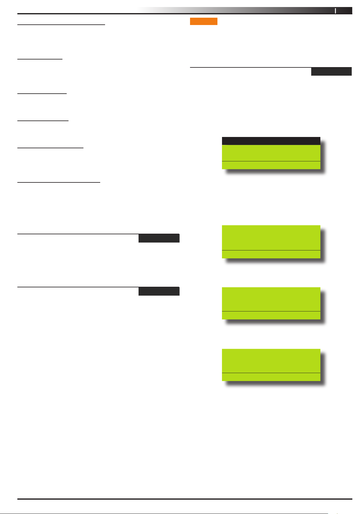
Main Office A001
Disarmed
Press OK or MENU
If the area is turned All On, the keypad will display:
Main Office A001
Armed All On
If the area is turned Part On, the keypad will display:
Main Office A001
Armed Part On
3. To exit, press [OK].
Issue 1.02
Copyright
© 2002-2004 Digflex Pty Ltd
Page 14
14
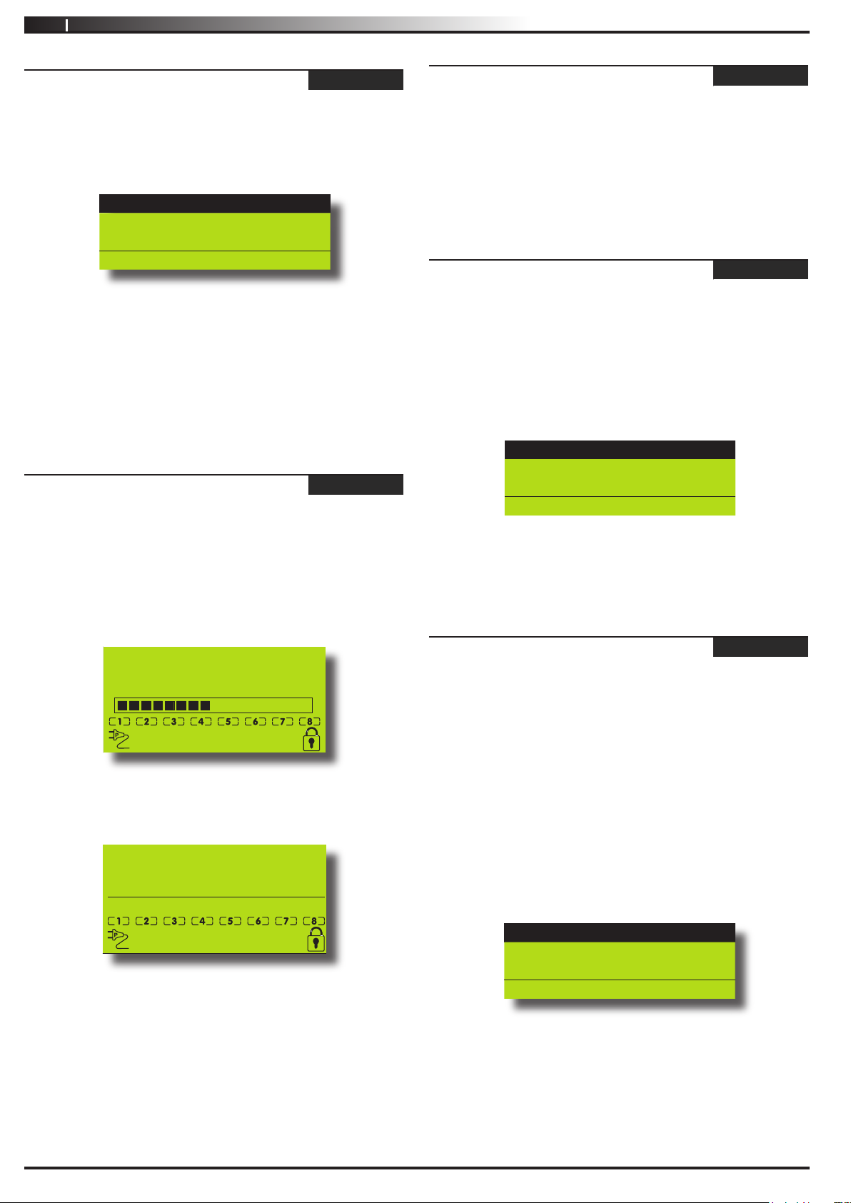
Area 1 Name
EXIT
NOW
Area 1 Name
ARMED
Fri,Aug,13 5:34 pm
Vision-64 User Guide
Areas > Commands >
Turn Area On/Off
MENU 2-0-1
This menu allows you to turn an area All On or off.
1. Enter [MENU] + [2] + [0] + [1].
A list of different areas will display on the keypad.
A001 Reception Area
A002 Sales Dept
A003 Administration Dept
Press , OK or MENU
If an area has already been turned All On or Part On, a
‘tick’ () will be displayed on the right side of the name
description (see A002 Sales Dept above).
2. Use the [
turn on or off, then press [OK] to select. Alternatively, you
can enter the area number you want to turn on or off, then
press [OK].
Areas > Commands >
Turn All Areas On
↑] and [↓] keys to select the area that you want to
MENU 2-0-2
This menu allows you to turn on all areas that your PIN has been
assigned to at the same time All On. The keypad display below
shows the area icons 1 through to 8.
1. Enter [MENU] + [2] + [0] + [2].
The keypad will display the exit time bar to prompt you to
exit all areas. You should leave all areas now.
Areas > Commands >
Turn All Areas Off
MENU 2-0-3
This menu allows you to turn off all areas that your PIN has been
assigned to at the same time. However, this menu requires at least
one area that has a keypad assigned to it to be disarmed before you
can access this command.
1. Enter [MENU] + [2] + [0] + [3].
Areas > Commands >
Move To Area
MENU 2-0-4
This menu allows you to operate multiple areas from the same
keypad when the system has been partitioned. Before operating a
different area, you will need to move the keypad to the area that
you want to operate.
1. Enter [MENU] + [2] + [0] + [4].
A list of different areas will display on the keypad.
A001 Reception Area
A002 Sales Dept
A003 Administration Dept
Press , OK or MENU
2. Use the [↑] and [↓] keys to select the area that you want
to move the keypad display to, then press [OK] to select.
Alternatively, you can enter the area number that you want
to move the keypad display to, then press [OK].
Areas > Commands >
Chime On/Off
MENU 2-0-5
When exit time has expired, the keypad will display that all
areas are turned All On (Armed).
Note:
Area icons will only display if programmed to
do so by your security installer.
Note: Area icons will only display if programmed to do
so by your security installer.
i
Issue 1.02
Chime mode allows you to monitor a zone (or group of zones)
to sound the keypad buzzer or activate a programmable output
when the corresponding area is turned off (disarmed). This can
be useful when you need to monitor the front or back entrance to
the premises.
This menu allows a user to turn chime mode on or off. Only
keypads programmed to sound the chime tone will be heard when
a zone programmed for chime is faulted.
The master user can Set Chime Zones on page ????. This allows the
master user to program which zones can be monitored for chime.
1. Enter [MENU] + [2] + [0] + [5].
A list of different areas will display on the keypad.
A001 Reception Area
A002 Sales Dept
A003 Administration Dept
Press OK or MENU
2. Use the [↑] and [↓] keys to select the area that you want
to turn chime mode on or off, then press [OK] to select.
Alternatively, you can enter the area number that you want
to turn chime mode on or off, then press [OK].
Copyright
© 2002-2004 Digflex Pty Ltd
Page 15
Vision-64 User Guide
15
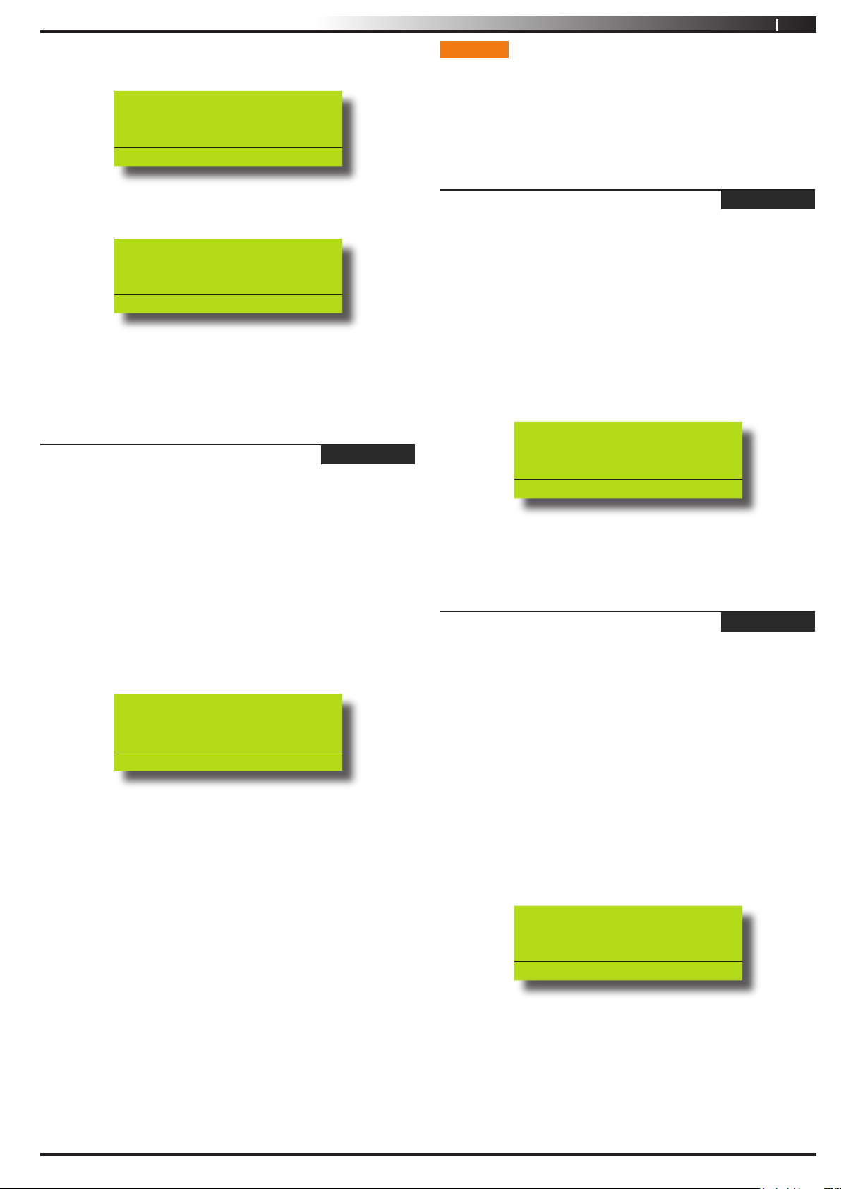
The keypad will display the following when chime mode is
turned off:
Reception Area A001
Chime Is OFF,
To Turn ON, Press ON.
To Go Back Press OK
The keypad will display the following when chime mode is
turned on:
Reception Area A001
Chime Is ON,
To Turn OFF, Press OFF.
To Go Back Press OK
3. Press the [ON] key to turn chime mode on, or, press [OFF]
to turn chime mode off.
4. Press the [OK] key to exit.
Areas > Area Properties >
Area Name
MENU 2-1-0
INPUTS
Each Vision-64 control panel has up to a maximum 64 zones. 16
zones are available as standard with an additional 48 wireless zones
available when the optional radio received is fitted. Your installer
will advise you on the exact makeup and configuration of your
system.
Inputs > Commands >
Zone Status
MENU 3-0-0
This menu allows you to view the zone status of each zone (i.e.
Normal, Open or Short).
1. Enter [MENU] + [3] + [0] + [0].
A list of different zones will display on the keypad.
2. Use the [
turn view the status information then press [OK] to select.
Alternatively, you can enter the zone number that you want
to view status information, then press [OK].
The keypad will display the following zone status information:
↑] and [↓] keys to select the zone that you want to
Zone 1 Name Z001
EOL=Normal 06523 ohms
This menu allows you to program the name for each area. Each
area name can be programmed with up to 16 characters. At factory
default, only Area 1 is used. The Vision control panel can have a
maximum of 8 independent areas programmed.
1. Enter [MENU] + [2] + [1] + [0].
A list of different areas will display on the keypad.
2. Use the [↑] and [↓] keys to select the area that you want to
program the name, then press [OK] to select. Alternatively,
you can enter the area number that you want to program
the name, then press [OK].
The keypad will display the following:
Area Name A001
Area 1 Name
Press ◄► OK to SAVE
3. Use the [←] and [→] keys to scroll the cursor left and right
across the area name text. Use the [
through the different characters available. To clear all text
from the cursor position to the right, press the [OFF] key.
4. When the user name is complete, press [OK].
↑] and [↓] keys to scroll
Press OK or MENU
3. Press the [OK] key to exit.
Inputs > Commands >
Bypass Zones
MENU 3-0-2
This menu allows you to bypass or un-bypass a single or multiple
zones before you turn the area All On, Part On or Part 2 On. When
bypassing zones, it disables the ability for a zone to detect intrusion
and sound an alarm.
A burglary zone will automatically become un-bypassed when you
turn the corresponding area off (disarm). Any 24-Hr fire or 24-Hr
non fire zones will need to be manually un-bypassed.
1. Enter [MENU] + [3] + [0] + [2].
A list of zones that can be bypassed will display on the
keypad. A ‘√’ displayed on the right side of the zone name
indicates that the zone is already bypassed.
Issue 1.02
Z001 Zone 1 Name
Z002 Zone 2 Name
Z003 Zone 3 Name
Press OK or MENU
2. Use the [↑] and [↓] keys to select the zone that you want to
bypass, then press [OK]. Alternatively, you can enter the
zone number that you want to bypass, then press [OK].
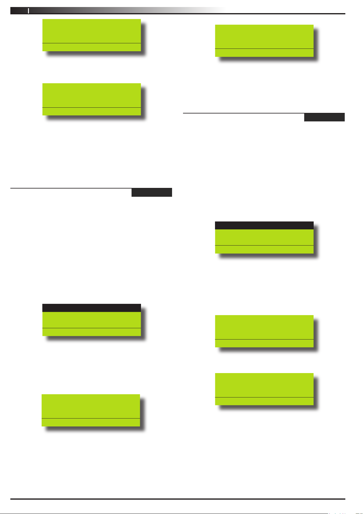
If the zone is bypassed, the keypad will prompt:
Copyright
© 2002-2004 Digflex Pty Ltd
Page 16
16
Vision-64 User Guide
Zone 1 Name Z001 is
bypassed. To un-bypass,
press OFF.
Press OK or MENU
If the zone is not bypassed, the keypad will prompt:
Zone 1 Name Z001 is
un-bypassed. To bypass,
press ON.
Press OK or MENU
3. Press [ON] or [OFF] to toggle the zone to be bypassed/unbypassed.
4. Press [OK] to save and exit, or press [MENU] to exit without
saving.
Repeat steps 1 to 4 to bypass or un-bypass additional zones.
Inputs > Commands >
Set Chime Zones
MENU 3-0-3
This menu allows you to program zones to be monitored when the
system is turned off. Chime mode is ideal to monitor a front door
to sound the keypad buzzer when opened (faulted).
1. Enter [MENU] + [3] + [0] + [3].
A list of areas will display on the keypad.
2. Use the [
to program zones for chime mode, then press [OK].
Alternatively, you can enter the area number that you want
to program chime zones, then press [OK].
The keypad will list all zones that can be programmed for
chime mode. A ‘’ displayed on the right side of the zone
name indicates that the zone is already set for chime.
] and [] keys to select the area that you want
Z001 Zone 1 Name
Z002 Zone 2 Name
Z003 Zone 3 Name
Press OK or MENU
3. Use the [↑] and [↓] keys to select the zone that you want to
set for chime, then press [OK]. Alternatively, you can enter
the zone number that you want to set for chime, then press
[OK].
If the zone is not programmed for chime, the keypad will
prompt:
Zone 1 Name Z001
Zone Chime is OFF,
To turn ON, Press ON.
To Go Back Press OK
If the zone is programmed for chime, the keypad will
prompt:
Zone 1 Name Z001
Zone Chime is ON.
To turn OFF, Press OFF.
To Go Back Press OK
4. Press [ON] or [OFF] to toggle the zone to be monitored
when chime mode is turned on.
5. Press [OK] to save and exit, or press [MENU] to exit without
saving.
Inputs > Commands >
Set Part 2 Zones
MENU 3-0-4
This menu allows you to program which zones are to be monitored
when an area has been turned Part 2 On.
1. Enter [MENU] + [3] + [0] + [4].
A list of areas will display on the keypad.
2. Use the [
program zones for Part 2 On, then press [OK]. Alternatively,
you can enter the area number that you want to program
Part 2 On zones, then press [OK].
The keypad will list all zones that can be programmed for
Part 2 On. A ‘’ displayed on the right side of the zone
name indicates that the zone is already bypassed.
↑] and [↓] keys to select the area that you want to
Z001 Zone 1 Name
Z002 Zone 2 Name
Z003 Zone 3 Name
Press OK or MENU
3. Use the [↑] and [↓] keys to select the zone that you want to
set for Part 2, then press [OK]. Alternatively, you can enter
the zone number that you want to set for Part 2, then press
[OK].
If the zone is not programmed for Part 2, the keypad will
prompt:
Zone 1 Z001
Is not a PART2 Zone,
To Enable, Press ON.
To Go Back Press OK
If the zone is programmed for Part 2, the keypad will
prompt:
Zone 1 Z001
Is a PART2 Zone,
To remove, Press OFF.
To Go Back Press OK
4. Press [ON] to monitor the zone when the area is turned Part
2 On, or press [OFF] so that you do not monitor the zone
when the area is turned Part 2 On.
5. Press [OK] to save and exit, or press [MENU] to exit without
saving.
Issue 1.02
Copyright
© 2002-2004 Digflex Pty Ltd
Page 17
Vision-64 User Guide
17
Inputs > Commands >
Smoke Sensor Reset
MENU 3-0-5
This menu allows you to reset smoke sensors.
1. Enter [MENU] + [3] + [0] + [5].
A list of different areas will display on the keypad.
2. Use the [
to reset the smoke detectors, then press [OK] to select.
Alternatively, you can enter the area number, then press
[OK].
The keypad will display the following:
↑] and [↓] keys to select the area that you want
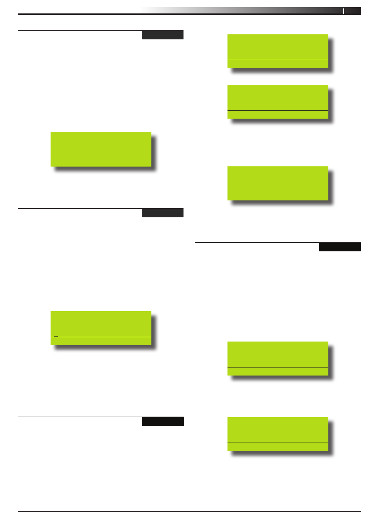
Smoke detector reset in
Progress. Please wait
3. The keypad will automatically return to the menu when all
smoke detectors in the area has been reset.
Inputs > Zone Properties >
Zone Name
MENU 3-1-0
This menu allows you to program up to 16 characters for the name
of each zone.
1. Enter [MENU] + [3] + [1] + [0].
A list of different zones will display on the keypad.
2. Use the [
want to change, then press [OK] to select. Alternatively, you
can enter the zone number, then press [OK].
The keypad will display the following:
↑] and [↓] keys to select the zone name that you
Zone Name Z001
Zone 1 Name
Press ◄► OK to SAVE
3. Use the [←] and [→] keys to scroll the cursor left and right
across the zone name text. Use the [
through the different characters available. To clear all text
from the cursor position to the right, press the [OFF] key.
4. Press [OK] to save and exit, or press [MENU] to exit without
saving.
Inputs > Input Testing >
Walk Test All Zones
↑] and [↓] keys to scroll
MENU 3-9-0
This menu allows you to test all zones within an area at the same
time. To successfully walk test each zone, you must open and close
each zone.
The keypad will scroll all zones that you can test.
To test Z001 open/close
Zone 1
Press OK or MENU
To test Z002 open/close
Zone 2
Press OK or MENU
3. Open and close each zone that needs to be tested. A zone
that has been successfully tested will no longer scroll on the
keypad display.
When all zones have been tested, the keypad will display:
Selected zones have been
Tested OK
Press OK or MENU
4. Press [OK] to save and exit, or press [MENU] to exit without
saving.
Inputs > Input Testing >
Walk Test A Single Zone
MENU 3-9-1
This menu allows you to select a single zone to be tested via walk
test.
1. Press [MENU] + [3] + [9] + [1].
The keypad will display a list of zones that are available to be
tested via walk test.
2. Use the [↑] and [↓] keys to select the zone that you want to
walk test, then press [OK] to select. Alternatively, you can
enter the zone number, then press [OK].
The keypad will display the zone to be tested.
To test Z001 open/close
Zone 1 Name
Press OK or MENU
3. Open and close the zone that needs to be tested.
When the zone has been successfully faulted and restored,
the keypad will display:
Z001 Zone 1 Name
Test Successful
Press OK or MENU
1. Press [MENU] + [3] + [9] + [0].
The keypad will display a list of areas that are available to
walk test zones.
2. Use the [
do walk test, then press [OK] to select. Alternatively, you
can enter the area number, then press [OK].
Issue 1.02
↑] and [↓] keys to select the area that you want to
4. Press [OK] to save and exit, or press [MENU] to exit without
saving.
Copyright
© 2002-2004 Digflex Pty Ltd
Page 18
18
Vision-64 User Guide
OUTPUTS
Each Vision-64 Vision control panel has up to a maximum of 8
outputs. 4 outputs are available as standard with an additional 4
available when the optional output expander is fitted. Your installer
will advise you on the exact makeup and configuration of you
system.
Outputs > Commands >
Output Status
MENU 4-0-0
This menu allows you to view the status of each output.
1. Ensure that the system is turned off.
2. Press [MENU] + [4] + [0] + [0].
The keypad will display a list of outputs that the status may
be viewed.
3. Using the [
to view the status information, then press [OK] to select.
Alternatively, you can enter the output number and then
press [OK].
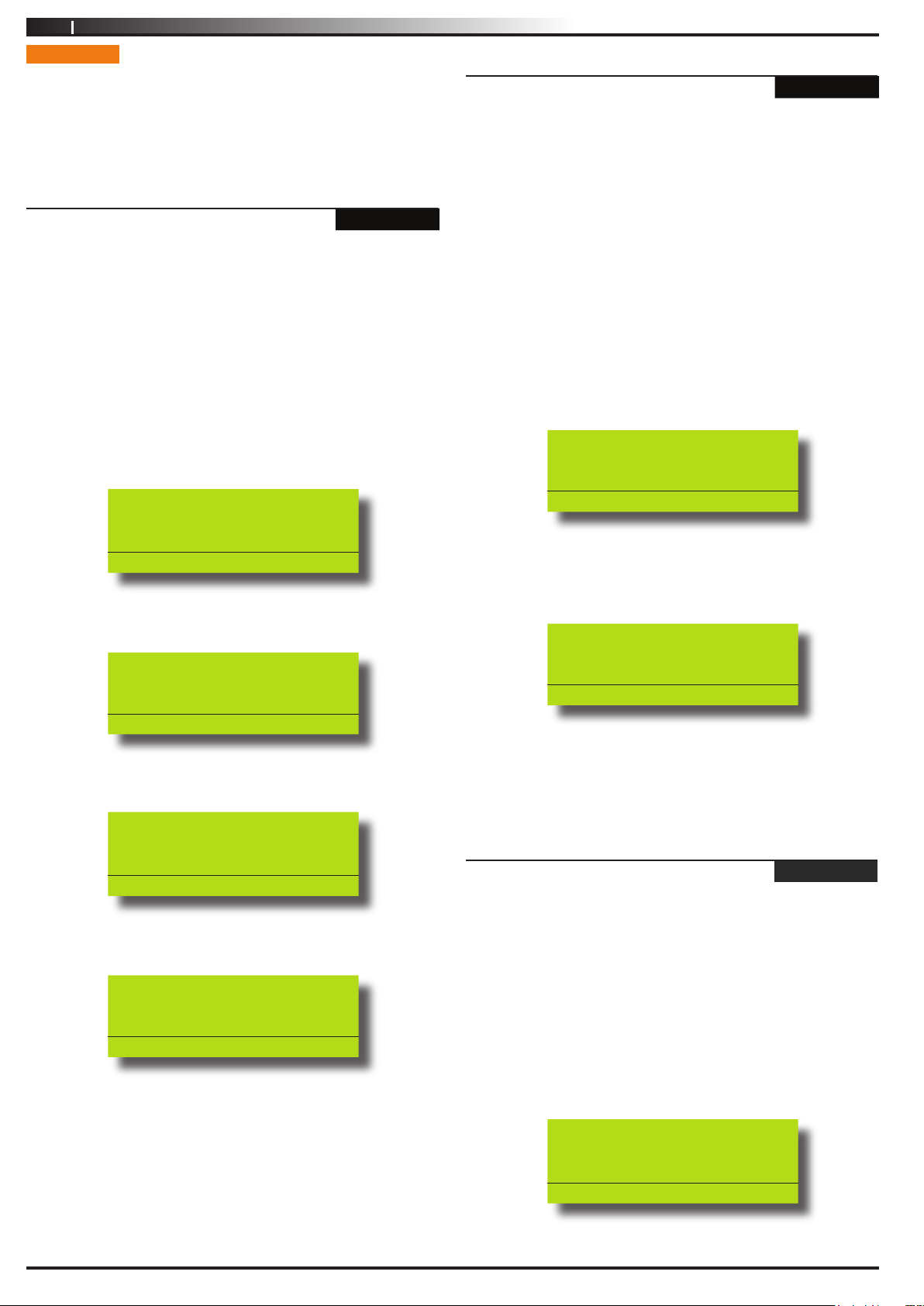
The keypad will display the following when the output is off
and OK:
↑] and [↓] keys, highlight the output that you want
Output 1 Name O001
Is Off and Ready
Press OK or MENU
Outputs > Commands >
Turn Output On/Off
MENU 4-0-1
This menu allows you to turn outputs that have been programmed
by your security company on or off. These outputs can be
programmed to control outside lighting, pool pumps, watering
systems etc.
1. Press [MENU] + [4] + [0] + [1].
If a valid PIN is required, the keypad will prompt you to
enter your PIN.
2. Use the [
want to change, then press [OK] to select. Alternatively, you
can enter the output number, then press [OK].
3. To toggle the output on or off, use the [ON] and [OFF] keys.
The keypad will display the following when the output is off:
↑] and [↓] keys to select the output name that you
Output 1 Name O001
Output is OFF,
To Turn ON,Press ON.
To Go Back Press OK
To turn the output on, press [ON].
The keypad will display the following when the output is off
and missing:
Output 1 Name O001
Is Off and Ready
Connection Trouble
Press OK or MENU
The keypad will display the following when the output is ON
and OK:
Output 1 Name O001
Is ON and Ready
Press OK or MENU
The keypad will display the following when the output is ON
and missing:
Output 1 Name O001
Is ON and Ready
Connection Trouble
Press OK or MENU
4. Press [OK] to save and exit, or press [MENU] to exit without
saving.
The keypad will display the following when the output is on:
Output 1 O001
Output is ON,
To Turn OFF,Press OFF.
To Go Back Press OK
To turn the output off, press [OFF].
4. Press [OK] to save and exit, or press [MENU] to exit without
saving.
Outputs > Properties >
Output Name
MENU 4-1-0
This menu allows you to program the name for each output. Each
output name supports up to 16 characters.
1. Enter [MENU] + [4] + [1] + [0].
A list of different outputs will display on the keypad.
2. Use the [
want to change, then press [OK] to select. Alternatively, you
can enter the output number, then press [OK].
The keypad will display the following:
↑] and [↓] keys to select the output name that you
Issue 1.02
Output Name O001
Output 1
Press ◄► OK to SAVE
3. Use the [←] and [→] keys to scroll the cursor left and right
across the output name text. Use the [
↑] and [↓] keys to
Copyright
© 2002-2004 Digflex Pty Ltd
Page 19
Vision-64 User Guide
19
scroll through the different characters available. To clear all
text from the cursor position to the right, press the [OFF]
key.
4. Press [OK] to save and exit, or press [MENU] to exit without
saving.
Outputs > Output Testing >
External Siren Test
MENU 4-9-0
This menu allows you to test any external sirens which have been
connected by your installer. The test will last for 5 seconds.
1. Enter [MENU] + [4] + [9] + [0].
If the system has been partitioned, the keypad will display a
list of areas.
A001 Area 1 Name
A002 Area 2 Name
A003 Area 3 Name
PRESS OK or MENU
2. Use the [↑] and [↓] keys to select the area that you want to
test the siren, then press [OK]. Alternatively, you can enter
the area number, then press [OK].
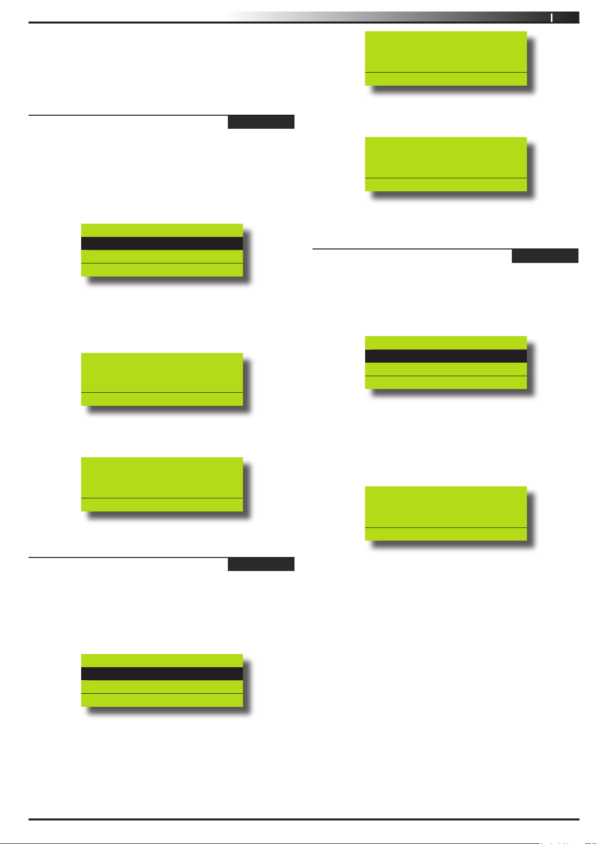
The keypad will display the following during the siren test.
External Audible
Testing Press any key to
abort
Press OK or MENU
When the siren test is complete, the keypad will display the
following:
Testing Complete. Press
OK to continue
Press OK or MENU
Internal Audible Testing
Press any key to abort
Press OK or MENU
When the bell test is complete, the keypad will display the
following:
Testing Complete. Press
OK to continue
Press OK or MENU
3. Press [OK] to exit.
Outputs > Output Testing >
Strobe Test
MENU 4-9-2
This menu allows you to test the external strobe light.
1. Enter [MENU] + [4] + [9] + [2].
If the system has been partitioned, the keypad will display a
list of areas.
A001 Area 1 Name
A002 Area 2 Name
A003 Area 3 Name
PRESS OK or MENU
2. Use the [↑] and [↓] keys to select the area that you want to
test the strobe, then press [OK].
Alternatively, you can enter the area number, then press
[OK].
The keypad will display the following during the strobe test.
Strobe Activated. Will
Reset On exit
3. Press [OK] to exit.
Outputs > Output Testing >
Internal Siren Test
MENU 4-9-1
This menu allows you to test any internal sirens which have been
connected by your installer. The test will last for 5 seconds.
1. Enter [MENU] + [4] + [9] + [1].
If the system has been partitioned, the keypad will display a
list of areas.
A001 Area 1 Name
A002 Area 2 Name
A003 Area 3 Name
PRESS OK or MENU
2. Use the [↑] and [↓] keys to select the area that you want to
test the bell, then press [OK]. Alternatively, you can enter
the area number, then press [OK].
The keypad will display the following during the bell test.
Issue 1.02
Press OK or MENU
Check and verify that the strobe light is on.
3. Press [OK] to exit.
Copyright
© 2002-2004 Digflex Pty Ltd
Page 20
20
Vision-64 User Guide
COMMUNICATION / REPORTING
Programming options in this section relate to how you alarm syetm
will communicate alarm information. Your installer will advise you
on the exact makeup and configuration of you system.
Comms > Commands >
Call/Answer RAS
MENU 5-0-1
This menu allows you to initiate a modem call to the installer’s
off-site computer for programming changes or updates. Your
installer may request that you enter this command so that they can
remotely service and configure you system. You should not enter
this command unless requested to do so.
Comms > Commands >
Call Forward On/Off
MENU 5-0-2
This menu allows you to turn on and off the call forward feature.
When you turn on call forwarding, the Vision control panel will
automatically activate and de-activate the call forward on and call
forward off sequence accordingly when you turn Area 1 All On and
off (arm and disarm).
1. Enter [MENU] + [5] + [0] + [2].
If the call forward status is off, the keypad will display:
Comms > Commands >
Set Domestic Phone Number
MENU 5-1-5
Domestic reporting allows the Vision control panel to send reports
to personal telephone numbers (eg. mobile telephone numbers).
Up to three different telephone numbers can be programmed,
each having a maximum of 32 digits.
A telephone call needs to be acknowledged by the user that answers
the incoming call. If the user fails to acknowledge the call, the
Vision control panel will make another attempt to report until the
maximum number of call attempts are reached. To acknowledge
the call, the user needs to press the [#] key on their telephone.
1. Enter [MENU] + [5] + [1] + [5].
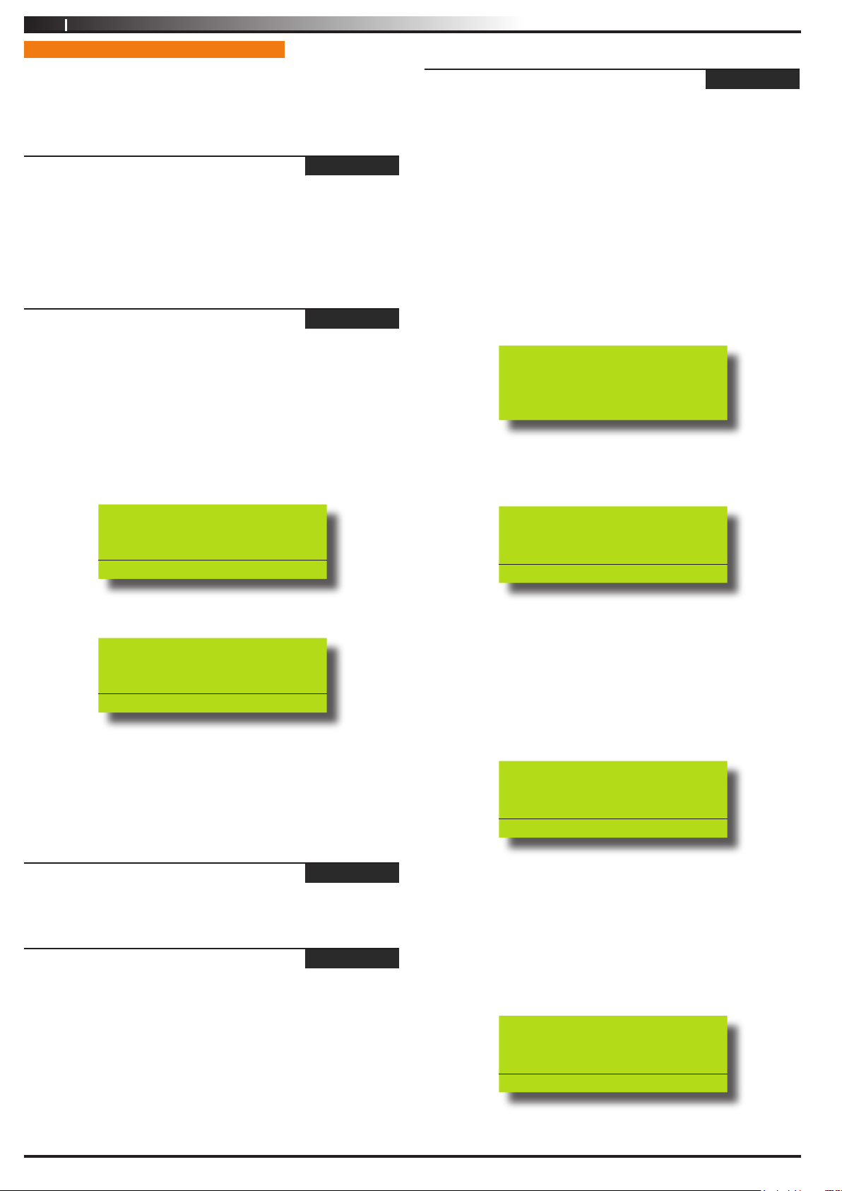
If the control panel is configured to report via domestic
format, the keypad will display the following:
Domestic Reports Not
Enabled. Please contact
Your Security Service
Provider
If the control panel has been configured to report via
domestic format, the keypad will display information for
telephone number 1.
Call Forward On/Off
Call Forward is OFF,
To turn ON, Press ON.
To Go Back Press OK
If the call forward status is on, the keypad will display:
Call Forward On/Off
Call Forward is ON,
To turn OFF, Press OFF.
To Go Back Press OK
2. To toggle call forward on, press the [ON] key or press the
[OFF] key to turn call forward off.
3. Press [OK] to save and exit, or press [MENU] to cancel.
Comms > Commands >
Check Web Email
MENU 5-0-3
Reserved
Comms > Commands >
Email System Log
MENU 5-0-4
Domestic Phone Number 1
631728_
Press 0-9 OK to SAVE
2. Using the numeric keys, enter all the digits of the first
telephone number.
You can change a single digit by scrolling the cursor left [
and right [→]. For special characters (eg. , = pause * or
# etc), use the [↑] and [↓] keys. To clear all text from the
cursor position to the right, press the [OFF] key.
3. Press [OK] to program telephone number 2.
Domestic Phone Number 2
4331_
Press 0-9 OK to SAVE
4. Using the numeric keys, enter all the digits of the second
telephone number (if required).
You can change a single digit by scrolling the cursor left [
and right [→]. For special characters (eg. , = pause * or
# etc), use the [↑] and [↓] keys. To clear all text from the
cursor position to the right, press the [OFF] key.
←]
←]
Reserved
Issue 1.02
5. Press [OK] to program telephone number 3.
Domestic Phone Number 3
6789_
Press 0-9 OK to SAVE
Copyright
© 2002-2004 Digflex Pty Ltd
Page 21
Vision-64 User Guide
21
6. Using the numeric keys, enter all the digits of the third
telephone number (if required).
You can change a single digit by scrolling the cursor left [
and right [→]. For special characters (eg. , = pause * or
# etc), use the [↑] and [↓] keys. To clear all text from the
cursor position to the right, press the [OFF] key.
7. Press [OK] to save and exit, or press [MENU] to cancel.
Comms > Commands >
Call Forward On Number
MENU 5-1-6
←]
When you leave your premises, you no longer need to remember
to manually activate the Call Forward On feature via the telephone.
These addresses allow you to program the Call Forward On
sequence that the Vision control panel will automatically use when
you turn Area 1 ‘On’.
In Australia, a typical sequence of activating the Call-Forward On
– After Time (All Calls) is described below:
For other countries please substitute the appropriate commands after
consultaion with your telephone company.
1. *61 (To turn Call Forward On – After Time).
2. Telephone number that you want calls to go to (e.g.
0416123456).
3. *5# (End of Call Forward sequence after 5 seconds).
Therefore, you would program the above steps as follows:
*610416123456*5#.
1. Enter [MENU] + [5] + [1] + [6].
The keypad will display information for telephone number 1.
Call Forward On N001
Comms > Commands >
Call Forward Off Number
MENU 5-1-7
When you enter your premises, you no longer need to remember
to manually disable the Call Forward feature via the telephone.
These addresses allow you to program the Call Forward Off
sequence that the Vision control panel will automatically use when
you turn Area 1 ‘Off’.
In Australia, a typical sequence of activating the Call Forward Off
feature is described below:
For other countries please substitute the appropriate commands after
consultaion with your telephone company.
1. #61 (To turn Auto-Forward After Time - Off).
2. # (End of Call-Forward sequence).
Therefore, you would program the above steps as follows:
#61#
1. Enter [MENU] + [5] + [1] + [7].
The keypad will display the current call-forward off sequence.
Call Forward Off N001
_
Press 0-9 OK to SAVE
2. Using the numeric keys, enter all the digits of the call
forward off sequence.
You can change a single digit by scrolling the cursor left [
and right [→]. For special characters (eg. , = pause, * or #
etc), use the [↑] and [↓] keys.
←]
Press 0-9 OK to SAVE
2. Using the numeric keys, enter all the digits of the call
forward on sequence.
You can change a single digit by scrolling the cursor left [
and right [→]. For special characters (eg. , = pause * or #
etc), use the [↑] and [↓] keys.
3. Press [OK] to save and exit, or press [MENU] to exit without
saving.
←]
3. Press [OK] to save and exit, or press [MENU] to exit without
saving.
Comms > Registration >
Customer
MENU 5-5-0
Reserved
Comms > Periodic Test >
Send Test Report
MENU 5-9-0
This menu allows you to test the reporting functions of the Vision
control panel by manually sending a ‘Test’ report to the receiving
party (i.e. security company monitoring station, mobile telephone
etc).
1. Enter [MENU] + [5] + [9] + [0].
The keypad will prompt that it is in the process of sending a
test report.
Comms testing in
progress. Please wait..
Issue 1.02
To Go Back Press OK
Copyright
© 2002-2004 Digflex Pty Ltd
Page 22
22
Vision-64 User Guide
If the test is successful, the keypad will prompt:
Communications Test
Successful
If the test is NOT successful, the keypad will prompt:
Test Report Failed
Please call for service
Press OK or MENU
2. Press [OK] or [MENU] to exit.
DEVICES AND OPTIONAL MODULES
Programming options in this section relate to the keypads and
other devices which may be connected to your alarm system. Your
installer will advise you on the exact makeup and configuration of
your system.
Devices > Commands >
Keypad Status
The keypad status will display the following information:
Line 1 = Keypad Number
Line 2 = Type of Keypad
Line 3 = Toggle Voltage, Temperature and Area Assignment
information.
MENU 6-0-0
Devices > Commands >
X10 Status
Reserved
Devices > Commands >
LAN P/Supply
Reserved
Devices > Commands >
GSM Status
Reserved
Devices > Commands >
Ethernet Status
Reserved
Devices > Commands >
Access Status
Reserved
Devices > Commands >
X10 Status
Reserved
MENU 6-0-3
MENU 6-0-4
MENU 6-0-5
MENU 6-0-6
MENU 6-0-7
MENU 6-0-8
1. Press [MENU] + [6] + [0] + [0].
Kp001 Keypad 001
Kp002 Keypad 002
Exit
Press OK or MENU
2. Use the [↑] and [↓] keys to select the keypad that you want
to view, then press [OK] to select. Alternatively, you can
enter the keypad number, then press [OK]. The location of
the keypad you are at is displayed by the ( tick).
3. The keypad will display the status of the keypad.
Keypad 001 K001
Graphic + Prox V001
Volts = 13.87
Press OK or MENU
4. Press [OK] or [MENU] to exit.
Devices > Commands >
RF Status
MENU 6-0-1
Reserved
Devices > Commands >
Serial Status
Reserved
Issue 1.02
MENU 6-0-2
Copyright
© 2002-2004 Digflex Pty Ltd
Page 23
Vision-64 User Guide
L
Keypad 001 Volume
Press
SAVE
OK
to
H
L
Keypad 001 Contrast
Press
SAVE
OK
to
H
L
Keypad 001 Backlight
Press
SAVE
OK
to
H
23
Devices > Keypads >
Volume
MENU 6-1-0
This menu allows you to adjust the volume of the keypad’s buzzer.
Each keypad will need to have their volume adjusted separately.
1. Press [MENU] + [6] + [1] + [0].
The keypad will display:
2. Use the [←] and [→] keys or use the [↑] and [↓] keys to
increase or decrease the volume of the keypad buzzer until
the desired volume has been reached.
3. Press [OK] to save and exit, or press [MENU] to exit without
saving.
Devices > Keypads >
Contrast
MENU 6-1-1
This menu allows you to adjust the contrast of the keypad’s LCD
display. Each keypad can have their display adjusted separately.
SYSTEM EVENTS
Options in this section relate to programming of system wide
options and interpretation of system trouble events when and if
they occur. Some events such as open zones will appear and single
events while other may be grouped together. In this case you need
to drill down to see the specific detail for each event. Your installer
will advise you how to interrogate system trouble events.
System > Commands >
Panel Status
MENU 7-0-0
The panel staus menu displays the panel software version
information as well as highlighting any system troubles that
are currently in effect. This is a view only location.
System > Commands >
System Trouble
MENU 7-0-1
The System Trouble Menu displays all current system troubles in a
list format. Some trouble events require you to drill down and nonsystem trouble that are curent within the Vision control panel.
1. Press [MENU] + [7] + [0] + [1].
The keypad will display a list of all current system and non
system trouble conditions.
1. Press [MENU] + [6] + [1] + [1].
The keypad will display the contrast screen.
2. Use the [←] and [→] keys to adjust the bar until the desired
contrast is reached.
3.
Press [OK] to save and exit, or press [MENU] to exit without
saving.
Devices > Keypads >
Backlight
MENU 6-1-2
This menu allows you to adjust the brightness of the keypad’s
LCD display backlight. Each keypad can have their display adjusted
separately.
1. Press [MENU] + [6] + [1] + [2].
The keypad will display the backlight screen.
To determine the system trouble condition, highlight the
panel number (P001 to P002) that you want to view using
the [↑] and [↓] keys, then press [OK] to select.
P001 System Trouble
Z001 Zone 1 Name
Z002 Zone 2 Name
Press OK or MENU
To determine the non system (zone) trouble condition,
highlight the zone number Z001 to Z064) that you want to
view using the [↑] and [↓] keys, then press [OK] to select.
P001 System Trouble
Z001 Zone 1 Name
Z002 Zone 2 Name
Press OK or MENU
2. If viewing system trouble conditions, the keypad will display
similar to the following:
Panel 001 P001
Voltage= 13.9V Temp=36
Date And Time
Press OK or MENU
Use the [←] and [→] keys to adjust the bar until the desired
2.
backlight is reached.
3.
Press [OK] to save and exit, or press [MENU] to exit without
saving.
Issue 1.02
The third line of the keypad display scrolls between all
current system trouble events.
If viewing non-system trouble conditions, the keypad will
display similar to the following:
Copyright
© 2002-2004 Digflex Pty Ltd
Page 24
24
Vision-64 User Guide
Zone 1 Name Z001
EOL = Open
1. Press [MENU] + [7] + [0] + [2].
The keypad will display the most recent event stored in the
history log.
Press OK or MENU
3. Press [OK] or [MENU] to exit the system trouble menu
command:
If there are no system troubles, the keypad will display:
There are no
System troubles.
Press OK or MENU
Refer to the Trouble Messages table for a complete list of
trouble events and their meanings.
System > Commands >
History Log
MENU 7-0-2
This menu allows you to review the last 256 history events (from
most recent to least recent).
Each event will display:
Line 1 - Displays Event Number
- Date / Time
- Destination 1 and/or 2 report status (S= Sent, P =
Pending, F = Fail, A = Abort and L = Log Only).
Line 2 - Displays the source of the event (eg. zone name and
zone number or user name and user number)
E001 Mon,01Oct 03:41 S1L2
Manual Test Report
Press OK or MENU
2. Use the [↑] and [↓] keys scroll between history events.
3. Press [OK] or [MENU] to exit.
System > Clock >
Set Date & Time
MENU 7-1-0
This menu allows you to program/adjust the date and time in the
Vision control panel.
1. Press [MENU] + [7] + [1] + [0].
The keypad will display the current date and time.
Set Date And Time
01-Jan-2004 04:37am
Press ◄► OK to SAVE
2. Use the [↑] and [↓] keys to program the month, day, year,
hour and minute. Use [←] and [→] keys to scroll cursor left
and right to between the month, day, year, hour and minute.
3. Press [OK] to save and exit, or press [MENU] to exit without
saving.
Line 3 - Displays the event description.
Issue 1.02
Copyright
© 2002-2004 Digflex Pty Ltd
Page 25
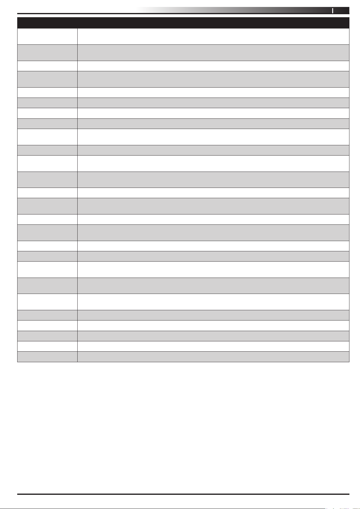
Trouble Condition Description
Vision-64 User Guide
25
Mains Missing
Battery Low
The system has detected that the AC mains supply has failed or is disconnected. If there is not a general power outage
in your area then you should contact your security company.
The backup battery has failed the periodic test which the system performs on a regular basis. You should contact your
security company as the battery may need replacing.
Battery Missing The system has detected that its backup battery has been disconnected.
Battery Reversed
The system has detected that backup battery has not been connected correctly.
You should contact your security company.
Voltage Low The voltage reading the keypad has fallen below the minimum programmed by the security company.
Voltage High The voltage reading at the keypad has increased above the maximum programmed by the security company.
RF Rxer Missing The system has detected that the RF receiver is disconnected.
RF Rxer Tamper
RF Rxer Jammed
The system has detected that the tamper circuit on the RF receiver is faulted.
The system has registered a jamming fault from the RF receiver. This situation may preven certain parts of your system
from working correctly. You should contact your security company.
Comms Trouble R1 The system has failed to send reports to the primary report contact. You should contact your security company.
Comms Trouble R2
Comms Test Fail
Buss Trouble
Default PIN Trbl
The system has failed to send reports to the secondary report contact.
You should contact your security company.
The system has failed to send its periodic report to the monitoring station.
You should contact your security company.
The system has failed to communicate to a system device (e.g. keypad etc).
The system has detected that either the Installer PIN or User 1 PIN has not been changed from the factory default codes.
These codes should be changed immediately to prevent a security risk.
Date And Time
Cabinet Tamper
Siren Trouble
Telco Line Trouble
LAN Overload
Comm+ Overload
Accessory Overld
The system date and time needs to be set.
The system has detected that someone has tampered with its metal enclosure or that it has been forced open. Inspect
and contact your security company if necessary.
The system has detected that the external siren has failed or has been disconnected from the system.
The system has detected that its telephone line has been disconnected for a minimum of 30 seconds.
The system has detected that the current load has exceeded the maximum LAN rating.
You should contact your security company.
The system has detected that the current load has exceeded it’s maximum COMM+ rating.
You should contact your security company.
The system has detected that the current load has exceeded it’s maximum ACCS+ rating.
You should contact your security company.
Time For Service The system displays this trouble condition to remind you that a service call is due.
Memory Fault The system has detected an error with its internal memory. You should contact your security company.
Default Memory The system memory has reset to factory default. You should contact your security company.
Service Mode The security installer has entered service mode.
Phone In Use The system is using the phone line.
Table 5: Vision-64 Trouble Messages
Issue 1.02
Copyright
© 2002-2004 Digflex Pty Ltd
Page 26
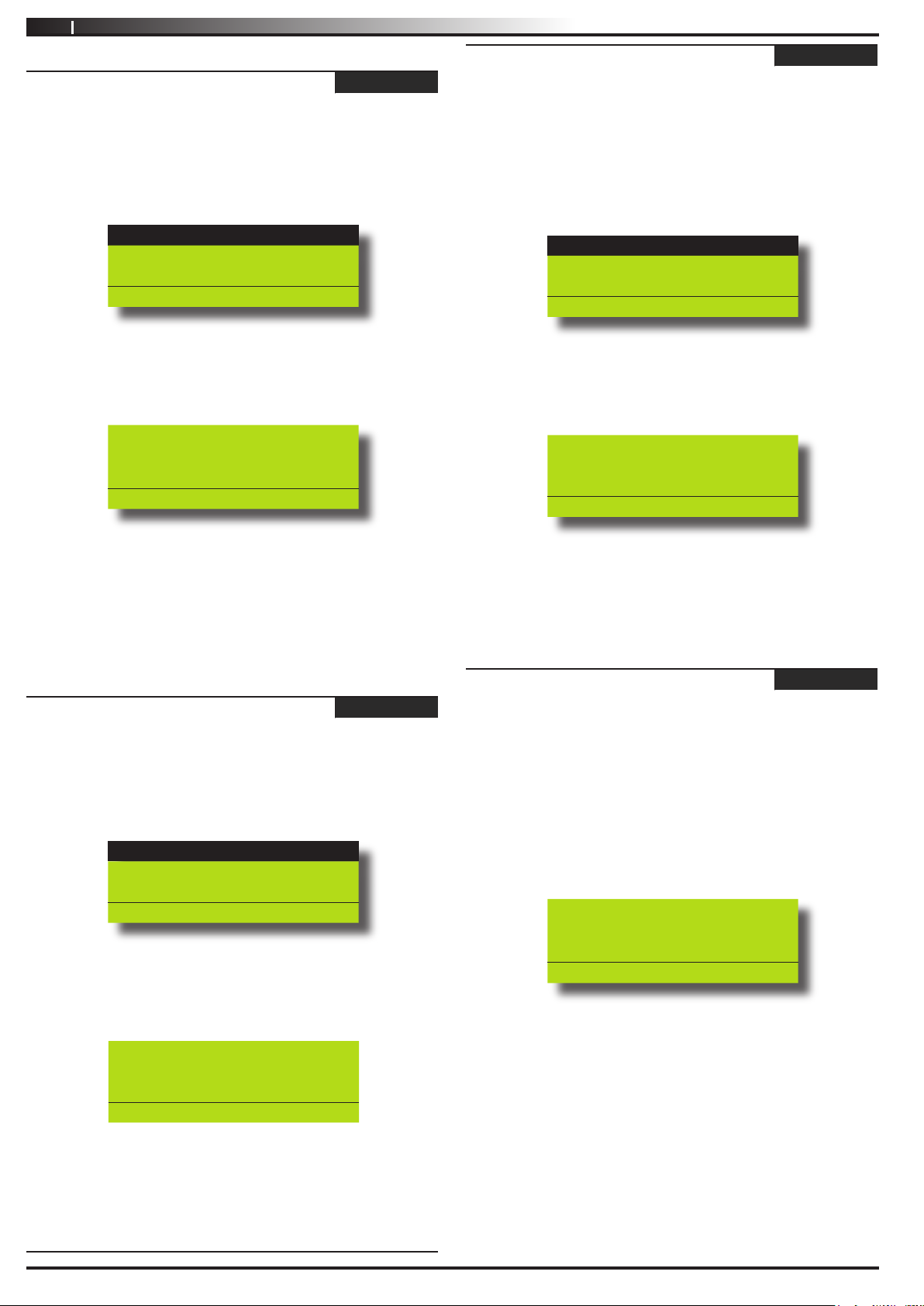
26
Vision-64 User Guide
System > Schedules >
Name
MENU 7-5-0
This menu allows you to program 16 characters of text for each
schedule name.
1. Enter [MENU] + [7] + [5] + [0].
A list of schedules will display on the keypad.
Sk001 Schedule 1 Name
Sk002 Schedule 2 Name
Sk003 Schedule 3 Name
Press OK or MENU
2. Use the [↑] and [↓] keys to select the schedule name that you
want to change, then press [OK] to select. Alternatively, you
can enter the schedule number, then press [OK].
The keypad will display the following:
Name S001
Schedule 1 Name
PRESS ◄► OK to SAVE
Day
MENU 7-5-2
This menu programs which days of the week the timer execute
function will operate. To toggle the day of the week on/off, press
the corresponding number on the keypad (e.g. to turn Monday on,
press [2] + [OK], to toggle Monday off, press [2] + [OK] ).
1. Enter [MENU] + [7] + [5] + [2].
A list of schedules will display on the keypad.
Sk001 Schedule 1 Name
Sk002 Schedule 2 Name
Sk003 Schedule 3 Name
Press OK or MENU
2. Use the [↑] and [↓] keys to select the schedule that you want
to change, then press [OK] to select. Alternatively, you can
enter the schedule number, then press [OK].
The keypad will display the following:
Day Sk001
S M T W T F S Hol
Y Y Y Y Y Y Y N
Press 1-8 OK to SAVE
3. To program the schedule name, use the [←] and [→] keys
to scroll the cursor left and right across the user name
text. Use the [
characters available. To clear all text from the cursor
position to the right, press the [OFF] key.
4. Press [OK] to save and exit, or press [MENU] to exit without
saving.
System > Schedules >
Time
↑] and [↓] keys to scroll through the different
MENU 7-5-1
This menu allows you to program both the start time and stop time
of each schedule.
1. Enter [MENU] + [7] + [6] + [2].
A list of schedules will display on the keypad.
Sk001 Schedule 1 Name
Sk002 Schedule 2 Name
Sk003 Schedule 3 Name
Press OK or MENU
2. Use the [↑] and [↓] keys to select the schedule that you want
to change, then press [OK] to select. Alternatively, you can
enter the schedule number, then press [OK].
The keypad will display the following:
Sk001 Schedule 1 Name
Start Time: 00:00
Stop Time: 00:00
Press 0-9 OK to SAVE
3. Enter the new start and stop times in 24-hour format (00:00
to 23:59 hours).
4. Press [OK] to save and exit, or press [MENU] to exit without
saving.
System > Schedules >
3. Press [1] to [8] to enable/disable the days of the week that
the schedule will operate.
4. Press [OK] to save and exit, or press [MENU] to exit without
saving.
System > Holidays >
Name
MENU 7-6-0
This menu allows you to program 16 characters for the holiday
name.
1. Enter [MENU] + [7] + [0] + [6].
A list of holiday names will display on the keypad.
2. Use the [
want to change, then press [OK] to select. Alternatively, you
can enter the timer number, then press [OK].
The keypad will display the following:
↑] and [↓] keys to select the timer name that you
Name H001
Holiday 1 Name
PRESS ◄► OK to SAVE
3. To program the holiday name, use the [] and [] keys to
scroll the cursor left and right across the user name text.
Use the [] and [] keys to scroll through the different
characters available. To clear all text from the cursor
position to the right, press the [OFF] key.
4. Press [OK] to save and exit, or press [MENU] to exit without
saving.
Issue 1.02
Copyright
© 2002-2004 Digflex Pty Ltd
Page 27
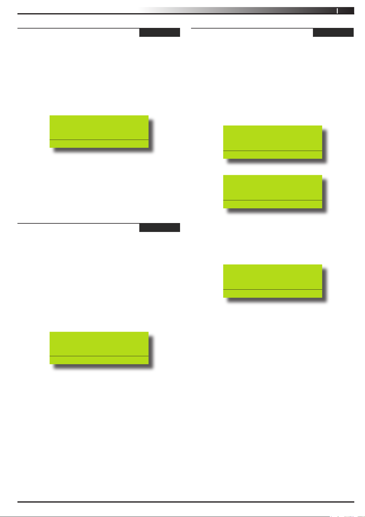
Vision-64 User Guide
27
System > Holidays >
Start / Stop Day
MENU 7-6-1
This menu allows you to program the start date and the stop date
of each holiday period.
1. Enter [MENU] + [7] + [6] + [1].
A list of holiday names will display on the keypad.
2. Use the [
to change, then press [OK] to select. Alternatively, you can
enter the holiday number, then press [OK].
The keypad will display the holiday start date:
↑] and [↓] keys to select the holiday that you want
Holiday Dates H001
Start Date Stop Date
01 Jan 01 Jan
Press ◄► OK to SAVE
3. To program the holiday start date and stop date, use the [↑]
and [↓] keys to scroll the cursor left and right between the
holiday day and month. Use the [←] and [→] keys to scroll
the day and month.
4. Press [OK] to save and exit, or press [MENU] to exit without
saving.
System > System Testing >
Walk Test All Zones
MENU 7-9-0
This menu allows you to test all zones within an area at the same
time.
1. Press [MENU] + [7] + [9] + [0].
The keypad will display a list of areas that are available to
walk test zones.
2. Use the [
do walk test, then press [OK] to select. Alternatively, you
can enter the area number, then press [OK].
The keypad will scroll all zones that you can test.
↑] and [↓] keys to select the area that you want to
To test Z001 open/close
Zone 1
Press OK or MENU
To test Z002 open/close
Zone 2
System > System Options >
Keypad Hi/Lo Temp
MENU 7-7-3
The keypad Hi/Lo temperature allows you to program the
minimum (0 °C) and maximum (50 °C) temperatures the keypad
will monitor (tolerance = +/- 2 °C).
If the temperature falls below the minimum temperature, the
keypad will display ‘Low Temp
˚xx’. If the temperature increases
above the maximum temperature, the keypad will display ‘High
temp ˚xx’.
(xx = programmed temperature to be monitored).
1. Press [MENU] + [7] + [7] + [3].
The keypad will display the current temperature settings.
Keypad Hi/Lo Temp
High Temp Low Temp
00 00
Press ◄► OK to SAVE
2. Use the [↑] and [↓] keys to program the ‘High’ and ‘Low’
temperatures. To toggle between the ‘High’ and ‘Low’
temperature, use the [←] and [→] keys (Range = 0°C to
50°C).
3. Press [OK] to save and exit, or press [MENU] to exit without
saving.
Press OK or MENU
3. Open and close each zone that needs to be tested. A zone
that has been successfully tested will no longer scroll on the
keypad display.
When all zones have been tested, the keypad will display:
Selected zones have been
Tested OK
Press OK or MENU
4. Press [OK] to save and exit, or press [MENU] to exit without
saving.
Issue 1.02
Copyright
© 2002-2004 Digflex Pty Ltd
Page 28

28
System > System Testing >
Battery Test
Vision-64 User Guide
MENU 7-9-1
This menu allows you to manually test the systems back up battery.
The Vision-64 will automatically test the battery once per day and
everytime the system is armed.
The battery test can take up to two minutes to complete and the
keypad will display the voltage of the battery during the test.
1. Press [MENU] + [7] + [9] + [2].
The keypad will display the battery voltage whilst under test:
Battery test in progress.
Please wait..
Voltage = 13.4V
To Go Back Press OK
If the battery has passed the test, the keypad will display:
Battery test Passed.
Press OK to continue
If the battery has failed the test, the keypad will display:
Battery test Failed.
Please Call for Service.
Press OK to continue
2. Press [OK] to exit.
Issue 1.02
Copyright
© 2002-2004 Digflex Pty Ltd
Page 29

Insta l l at ion Deta i l s
INSTALLED BY: DATE
PHONE: FAX:
EMAIL:
SERVICE
PHONE: FAX:
Vision-64 User Guide
29
EMAIL:
MONITORED BY:
PHONE: FAX:
EMAIL:
WARRANTY EXPIRES:
NOTES:
Issue 1.02
Copyright
© 2002-2004 Digflex Pty Ltd
Page 30

30
Vision-64 User Guide
Inde x
A
All On ................................................................... 7, 11
Area
Chime On/Off .......................................................23
Move To Area .......................................................22
Name ...................................................................23
Status ...................................................................20
Turn All Areas Off .................................................22
Turn All Areas On .................................................21
Turn On/Off ..........................................................21
Area Assignment
User .....................................................................16
B
Battery
Test ......................................................................48
Bypass
Zones ...................................................................24
C
Call Forward
Enable/Disable .....................................................33
Off Sequence .......................................................36
On Sequence .......................................................35
I
Inputs
Chime Zones .......................................................25
Part 2 Zones ........................................................26
Zone Bypass ........................................................24
Zone Status .........................................................24
K
Keypad
Display .................................................................38
Hi/Lo Temperature ...............................................46
Icon Descriptions ...................................................9
Keys .......................................................................8
LED Descriptions ...................................................9
Status ...................................................................37
Tones ...................................................................10
Volume .................................................................38
M
Move To Area ...........................................................
N
Name
Area .....................................................................23
Output ..................................................................31
O
22
Chime
Set Zones ............................................................25
Turn On/Off ..........................................................23
Clock
Date/Time ............................................................42
Comm’s
Call Forward Enable/Disable ...............................33
Call Forward Off ...................................................36
Call Forward On ...................................................35
Call/Answer RAS .................................................33
Check Web Email ................................................33
Customer Registration .........................................36
Domestic Numbers ..............................................34
Email System Log ................................................33
Test Report Send .................................................36
D
Date/Time ................................................................
42
F
Features ....................................................................6
H
Output
External Siren Test .........................................31, 32
Name ...................................................................31
Status ...................................................................29
Strobe Test ...........................................................32
Turn On/Off ..........................................................30
P
Part 2
Set Zones ............................................................26
Part On ................................................................7, 11
PIN
Add ......................................................................15
Area Assignment ..................................................16
Change Own ........................................................13
R
Registration
Customer .............................................................36
RF Keyfob
Add ......................................................................19
Delete ..................................................................20
Holidays
Name ...................................................................45
Start/Stop Days ....................................................45
Issue 1.02
S
Schedules
Name ...................................................................43
Time .....................................................................44
Security System Basics
Copyright
© 2002-2004 Digflex Pty Ltd
Page 31

Vision-64 User Guide
31
Are All Zones The Same? ......................................7
What Is A Faulted Zone .........................................7
What Is A Zone ......................................................7
Silencing Alarms ......................................................12
Smoke
Sensor Reset .......................................................27
Status
Area .....................................................................20
Keypad .................................................................37
System
Date/Time ............................................................42
History Log ...........................................................42
Holidays ...............................................................45
Schedules ............................................................43
Trouble .................................................................40
System Log
Email ....................................................................33
T
Telepermit Note .......................................................
48
Telephone Numbers
Call Forward Off ...................................................36
Call Forward On ...................................................35
Domestic ..............................................................34
Z
Zone
24-Hour Zones .......................................................7
Bypass Command ...............................................24
Chime...................................................................25
Non 24-Hour Zones ...............................................7
Part 2 Zones ........................................................26
Test Report
Send ....................................................................36
Testing
Battery Test ..........................................................48
Walk Test All Zones ..............................................47
Walk Test Single Zone .........................................28
Token
Delete ............................................................18, 19
Trouble ....................................................................40
Turn Off ...................................................................12
U
User
Area Assignment ..................................................16
User Options
Arm Only PIN .......................................................17
Auto Bypass Zones ..............................................17
Bypass Zones ......................................................17
Expire PIN ............................................................17
Master PIN ...........................................................17
Send ‘Open’ Reports ............................................17
W
Walk Test
All Zones ........................................................28, 47
Single Zones ........................................................28
Web Email ...............................................................33
Issue 1.02
Copyright
© 2002-2004 Digflex Pty Ltd
Page 32

DI G I F L EX P T Y LTD
Unit 5 , 8 Millennium C o u r t
Silverwater NSW 2128
AUSTRALIA
Phone: ( + 6 1 2 ) 97 417000
Facsim i l e : ( + 6 1 2 ) 9 7 4 17 000
www. d i g i f l e x . c om .au
Our Vision Is Your Peace Of Mind
Made in
Australia
Copyright © 2002-2004 Digiflex Pty Ltd
P/N : MACC110-U
 Loading...