

Digiever DS-8200-RM Pro, DS-4000, DS-4200-RM Pro, DS-4200-RMP Pro, DS-8200-RMP Pro User Manual
...Page 1

Network Video Recorder
User Manual
1.0.0.27
Information in this document is subject to change without notice.
© Copyright 2016. All rights reserved.
Page 2

Table of Contents
Chapter 1. Introduction ................................................................ ............. 1
1.1 Hardware Description ................................................................................. 2
1.1.1 DS-2000 Series ..................................................................................... 2
1.1.2 DS-4000 Series ..................................................................................... 3
1.1.3 DS-1100 Pro Series .............................................................................. 4
1.1.4 DS-2100 Pro Series .............................................................................. 5
1.1.5 DS-4200 Pro Series .............................................................................. 6
1.1.6 DS-4200-RM Pro Series ....................................................................... 7
1.1.7 DS-4200-RMP Pro Series..................................................................... 8
1.1.8 DS-8200-RM Pro Series ....................................................................... 9
1.1.9 DS-8200-RMP Pro Series................................................................... 10
1.1.10 DS-1100 Pro+ Series .......................................................................... 11
1.1.11 DS-2100 Pro+ Series .......................................................................... 12
1.1.12 DS-4200 Pro+ Series .......................................................................... 13
1.1.13 DS-4200-RM Pro+ Series ................................................................... 14
1.1.14 DS-4200-RMP Pro+ Series ................................................................ 15
1.1.15 DS-8200-RM Pro+ Series ................................................................... 16
1.1.16 DS-8200-RMP Pro+ Series ................................................................ 17
1.1.17 DS-4300 Pro+ Series .......................................................................... 18
1.1.18 DS-4300-RM Pro+ Series ................................................................... 19
1.1.19 DS-4300-RMP Pro+ Series ................................................................ 20
1.1.20 DS-8300-RM Pro+ Series ................................................................... 21
1.1.21 DS-8300-RMP Pro+ Series ................................................................ 22
1.1.22 DS-8400-RM Pro+ Series ................................................................... 23
1.1.23 DS-16200-RM Pro+ Series ................................................................. 24
1.1.24 DS-16300-RM Pro+ Series ................................................................. 25
1.1.25 DS-16400-RM Pro+ Series ................................................................. 26
1.1.26 DS-16500-RM Pro+ Series ................................................................. 27
1.1.27 MN-1100 Pro+ Series ......................................................................... 29
i
Page 3

1.1.28 MN-2100 Pro+ Series ......................................................................... 30
1.2 LED Indicators Status.................................................................................. 31
1.2.1 DS-2000 Series ................................................................................... 31
1.2.2 DS-4000 Series ................................................................................... 33
1.2.3 DS-1100 Pro Series ............................................................................ 35
1.2.4 DS-2100 Pro Series ............................................................................ 36
1.2.5 DS-4200 Pro Series ............................................................................ 37
1.2.6 DS-4200-RM Pro Series ..................................................................... 39
1.2.7 DS-4200-RMP Pro Series................................................................... 41
1.2.8 DS-8200-RM Pro Series ..................................................................... 43
1.2.9 DS-8200-RMP Pro Series................................................................... 45
1.2.10 DS-1100 Pro+ Series .......................................................................... 47
1.2.11 DS-2100 Pro+ Series .......................................................................... 48
1.2.12 DS-4200 Pro+ Series .......................................................................... 49
1.2.13 DS-4200-RM Pro+ Series ................................................................... 51
1.2.14 DS-4200-RMP Pro+ Series ................................................................ 53
1.2.15 DS-8200-RM Pro+ Series ................................................................... 55
1.2.16 DS-8200-RMP Pro+ Series ................................................................ 57
1.2.17 DS-4300 Pro+ Series .......................................................................... 59
1.2.18 DS-4300-RM Pro+ Series ................................................................... 61
1.2.19 DS-4300-RMP Pro+ Series ................................................................ 63
1.2.20 DS-8300-RM Pro+ Series ................................................................... 65
1.2.21 DS-8300-RMP Pro+ Series ................................................................ 67
1.2.22 DS-8400-RM Pro+ Series ................................................................... 69
1.2.23 DS-16200-RM Pro+ Series ................................................................. 71
1.2.24 DS-16300-RM Pro+ Series ................................................................. 73
1.2.25 DS-16400-RM Pro+ Series ................................................................. 75
1.2.26 DS-16500-RM Pro+ Series ................................................................. 77
1.2.27 MN-1100 Pro+ Series ......................................................................... 79
1.2.28 MN-2100 Pro+ Series ......................................................................... 80
ii
Page 4

1.3 Dual/Mirror Display Solution: HDMI/VGA/DVI-I Connection ............... 82
Chapter 2. NVR Installation ..................................................................... 83
2.1 Remote Web Browser PC System Requirements ................................... 83
2.2 Connect to NVR ......................................................................................... 84
2.2.1 Quick Guide ........................................................................................ 84
2.2.2 Install NVR Search ............................................................................. 84
2.2.3 Install NVR Decoder .......................................................................... 93
2.2.4 NVRPlayer ........................................................................................... 95
2.2.5 Install NVR Check .............................................................................. 98
2.2.6 User Manual ...................................................................................... 102
2.2.7 Browse CD ........................................................................................ 102
2.2.8 Activate Live View Service ............................................................. 103
2.3 Quick Configuration ................................................................................ 106
2.3.1 Start ................................................................................................... 106
2.3.2 Network Settings .............................................................................. 107
2.3.3 Server Settings ................................................................................. 108
2.3.4 Date & Time ...................................................................................... 109
2.3.5 Disk Management ............................................................................ 110
2.3.6 Camera Settings ............................................................................... 117
2.3.7 Finish ................................................................................................. 125
Chapter 3. Use NVR by Local Display .................................................. 126
3.1 Log in NVR ................................................................................................. 126
3.1.1 Anonymous login ............................................................................. 127
3.1.2 Virtual Keyboard .............................................................................. 128
3.1.3 Selectable Login Entry .................................................................... 128
3.2 Quick Configuration ................................................................................ 129
3.3 Liveview .................................................................................................... 129
3.3.1 Select View Modes on Liveview Page ........................................... 129
3.3.2 Main Functions of Liveview ............................................................ 130
3.3.3 Right Click Functions on Video Window ...................................... 138
iii
Page 5

3.3.4 Zooming with Mouse Scroll ............................................................ 140
3.3.5 Two-way Audio ................................................................................. 141
3.4 Playback ................................................................................................... 142
3.4.1 Steps to Playback Videos ............................................................... 142
3.4.2 Description of Recording Types .................................................... 145
3.4.3 Main Functions of Playback ........................................................... 146
3.4.4 Export Files....................................................................................... 148
3.4.5 Snapshot ........................................................................................... 149
3.4.6 Zooming with Mouse Scroll ............................................................ 149
3.5 Others ........................................................................................................ 149
3.5.1 Screenshot on Local Display ......................................................... 149
3.5.2 System Upgrade on Local Display ................................................ 150
3.5.3 USB Backup by Hardware or Software USB BACKUP Buttons ...... 150
Chapter 4. Use NVR by Remote Web Browser .................................... 150
4.1 Liveview .................................................................................................... 150
4.1.1 Select View Modes on Liveview Page ........................................... 151
4.1.2 Main Functions for Liveview .......................................................... 152
4.1.3 Right Click Functions on Video Window ...................................... 163
4.1.4 Zooming with Mouse scroll ............................................................ 165
4.1.5 Two-way Audio ................................................................................. 166
4.1.6 Built-in Mini-CMS Server ................................................................. 167
4.2 Multi-layer Dynamic E-Map ................................................................... 170
4.2.1 Feature Introduction ........................................................................ 171
4.2.2 Add or Delete Multi-layer E-Maps .................................................. 172
4.2.3 Deploy Cameras ............................................................................... 174
4.2.4 Enable/ Disable Automatically Pop-up Event Window ................ 175
4.2.5 Event Log History ............................................................................ 177
4.3 Playback ................................................................................................... 178
4.3.1 Steps to Playback Videos ............................................................... 178
4.3.2 Description of Recording Types .................................................... 182
iv
Page 6

4.3.3 Multi-NVR Playback ......................................................................... 183
4.3.4 Smart Search .................................................................................... 186
4.3.5 Main Functions on Playback .......................................................... 188
4.3.6 Zooming with Mouse scroll ............................................................ 193
4.3.7 Export ................................................................................................ 194
4.4 Play Video Files ........................................................................................ 199
4.4.1 Windows Networking ...................................................................... 199
4.4.2 FTP Service....................................................................................... 204
4.4.3 Naming Rule of Video files ............................................................. 207
Chapter 5. Configuration ....................................................................... 207
5.1 IP Camera ................................................................................................. 207
5.1.1 Camera Settings ............................................................................... 207
5.1.2 Camera Parameter ........................................................................... 208
5.1.3 Camera Status .................................................................................. 211
5.2 Recording & Events.................................................................................. 212
5.2.1 Recording Settings .......................................................................... 213
5.2.2 Recording Schedule ........................................................................ 215
5.2.3 Recording Group ............................................................................. 218
5.2.4 Event & Action Management .......................................................... 219
5.2.5 Advanced Setting............................................................................. 227
5.2.6 E-Mail ................................................................................................. 229
5.3 Disk Management ................................................................................... 231
5.3.1 Disk Management ............................................................................ 231
5.3.2 Storage Volume Management ........................................................ 232
5.3.3 File Sharing Service ........................................................................ 234
5.4 Cloud ......................................................................................................... 236
5.4.1 Setup Dropbox Service ................................................................... 236
5.4.2 Share Files to Dropbox Server ....................................................... 237
5.4.3 Remove Configuration and Online Sync ...................................... 238
5.5 Network Setup .......................................................................................... 239
v
Page 7

5.5.1 Network Setup .................................................................................. 239
5.5.2 Network Service ............................................................................... 244
5.5.3 DDNS ................................................................................................. 247
5.5.4 Wireless ............................................................................................ 248
5.5.5 3G/4G ................................................................................................. 250
5.6 Management ........................................................................................... 251
5.6.1 User Management ............................................................................ 251
5.6.2 Log System ....................................................................................... 256
5.6.3 Save/Load Configuration ................................................................ 259
5.6.4 USB Backup...................................................................................... 261
5.6.5 Remote Backup ................................................................................ 270
5.6.6 External IO Device ........................................................................... 272
5.6.7 UPS Management............................................................................. 273
5.6.8 Failover ............................................................................................. 275
5.6.9 SNMP ................................................................................................. 278
5.6.10 ModBus IO Device ........................................................................... 278
5.6.11 Access Control ................................................................................. 281
5.6.12 Stack Light ........................................................................................ 285
5.7 System ....................................................................................................... 287
5.7.1 Device Information........................................................................... 287
5.7.2 System Upgrade ............................................................................... 288
5.7.3 Language .......................................................................................... 291
5.7.4 Date &Time ....................................................................................... 292
5.7.5 Buzzer/Digital Output ...................................................................... 294
5.7.6 Reboot & Shutdown......................................................................... 295
Appendix: Notice and Warning ...................................................................... 297
vi
Page 8

Chapter 1. Introduction
Before You Use This Product
When you first open the product’s package, verify that all the accessories listed on
the “Package Contents” of “Quick Installation Guide” are included. Before installing
the NVR, please read the instructions in the “Quick Installation Guide” to avoid
misuse and then follow the instructions in the “Hard Disk Installation” section to
avoid damages due to faulty assembly or installation.
1
Page 9
1.1 Hardware Description
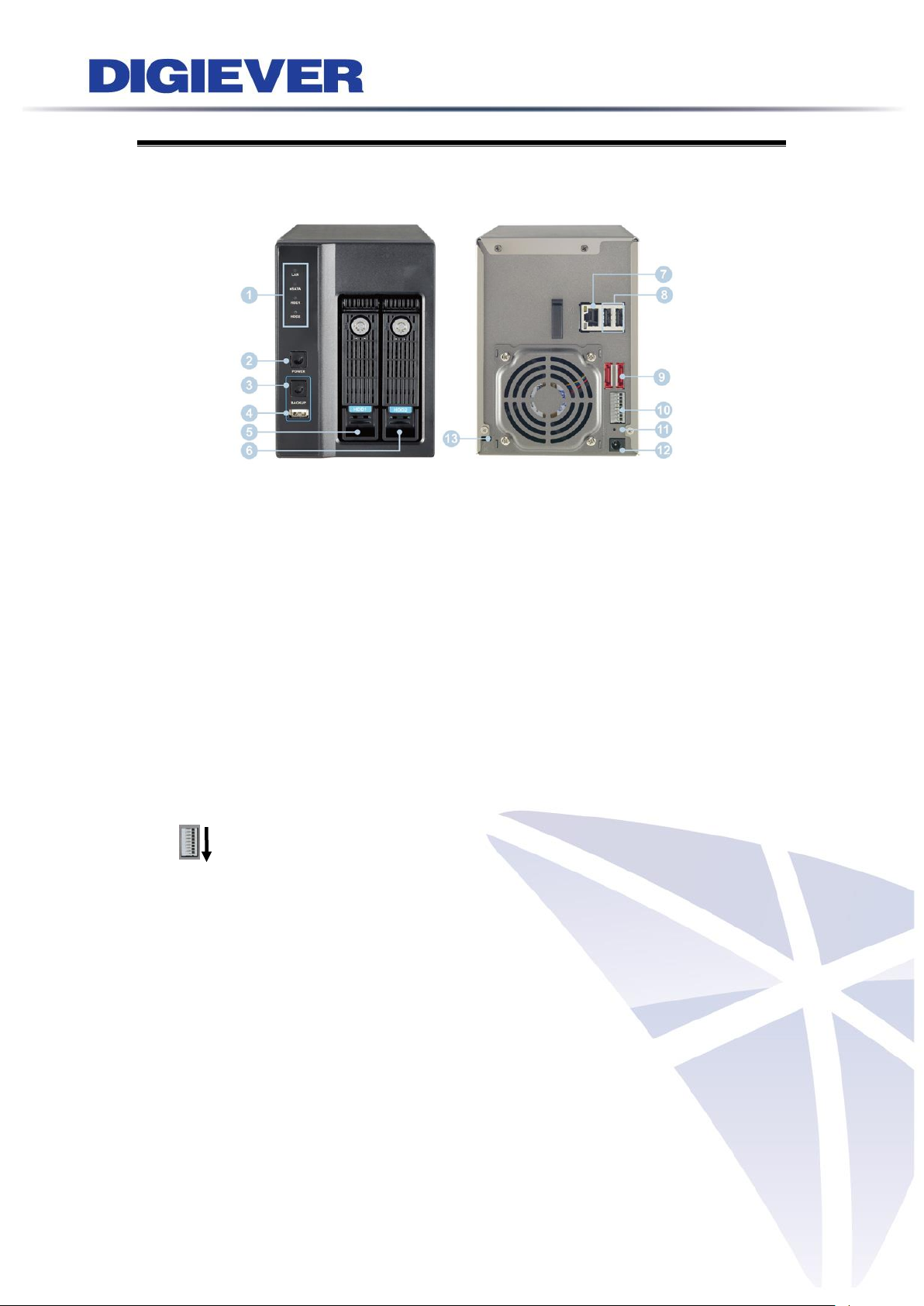
1.1.1 DS-2000 Series
DS-2005/DS-2009/DS-2012/DS-2016/DS-2020/DS-2025/DS-2032
Figure 1-1. Front & Rear View of DS-2000 Series
1. Figure LED indicators: LAN, eSATA, HDD1, HDD2
2. Power button
3. USB BACKUP button- Auto video backup
4. USB 2.0 X1(Support auto video backup)
5. HDD1
6. HDD2
7. Gigabit LAN
8. USB 2.0 x 2
9. eSATA x 2
10. DI/DO (4 in 2 out)
Top to bottom: Vcc5V, GND, DI-1, DI-2, DI-3, DI-4, DO-1, DO-2
11. Reset button*
12. Power connector
13. K-lock security slot
2
Page 10
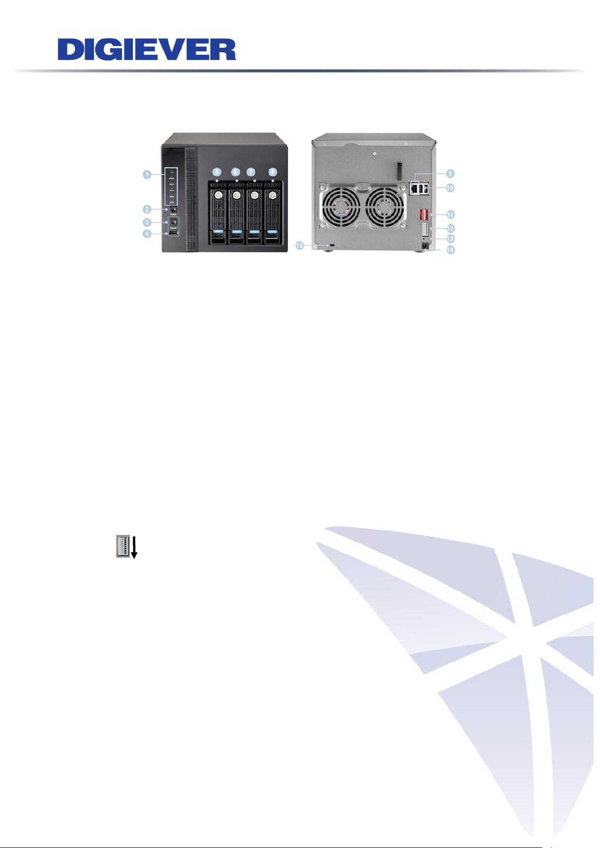
1.1.2 DS-4000 Series
DS-4005/DS-4009/DS-4012/DS-4016/DS-4020/ DS-4025/ DS-4032
Figure 1-2. Front & Rear View of DS-4000 Series
1. LED indicators: LAN, eSATA, HDD1, HDD2, HDD3, HDD4
2. Power button
3. USB BACKUP button- Auto video backup
4. USB 2.0 x 1 (Support auto video backup)
5. HDD1
6. HDD2
7. HDD3
8. HDD4
9. Gigabit LAN
10. USB 2.0 x 2
11. eSATA x 2
12. DI/DO (4 in 2 out)
Top to bottom: Vcc5V, GND, DI-1, DI-2, DI-3, DI-4, DO-1, DO-2
13. Reset button*
14. Power connector
15. K-lock security slot
3
Page 11
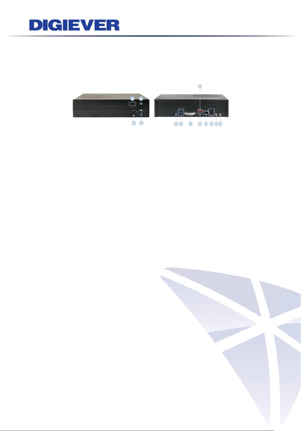
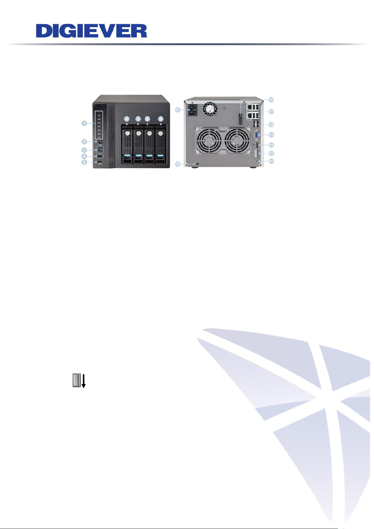
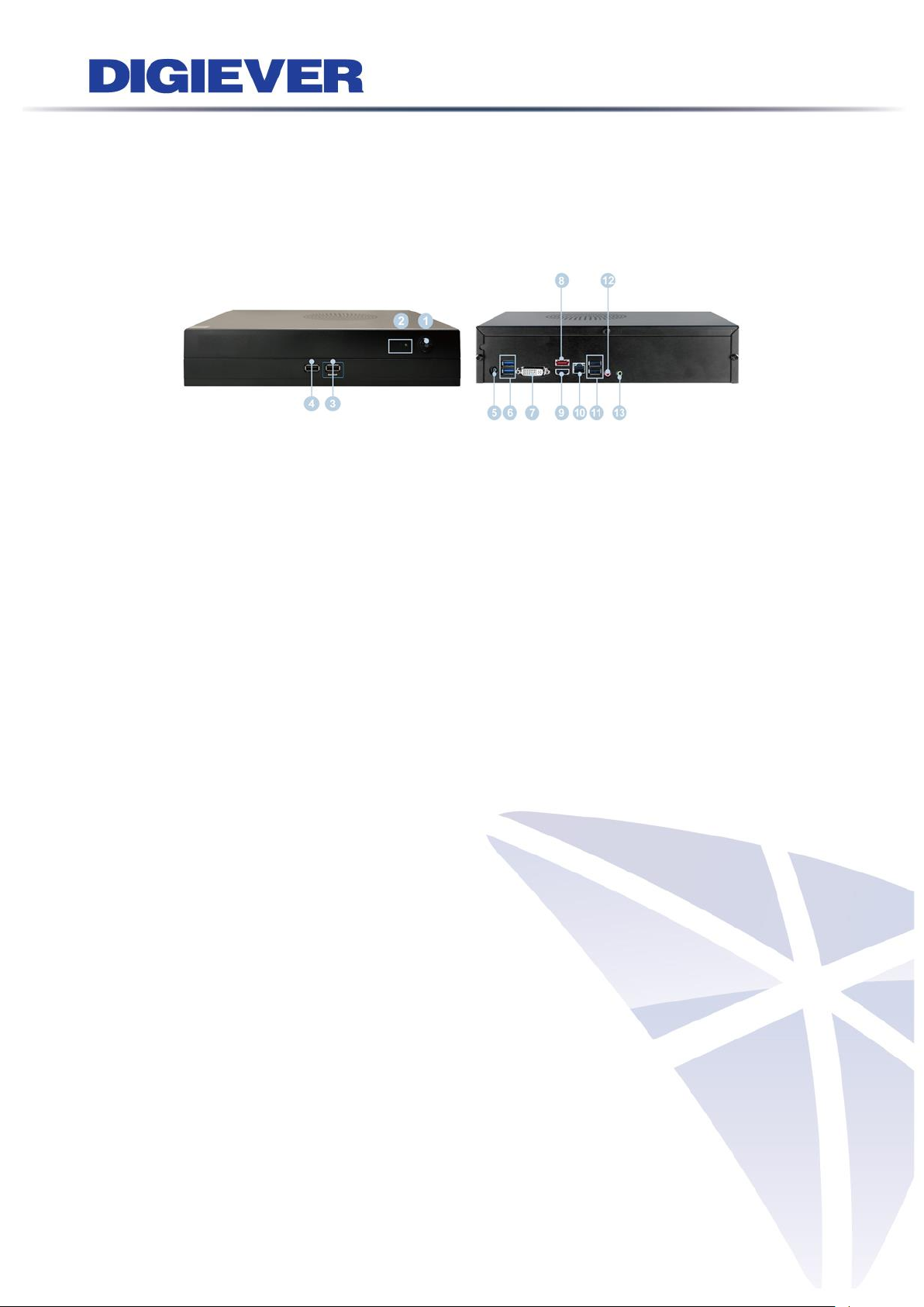
1.1.3 DS-1100 Pro Series
DS-1105 Pro/ DS-1109 Pro/ DS-1112 Pro/ DS-1116 Pro/ DS-1120 Pro/ DS-1125 Pro/
DS-1132 Pro/ DS-1136 Pro
Figure 1-3. Front & Rear View of DS-1100 Pro Series
1. Power button
2. LED indicators: HDD
3. USB 2.0 x1 (Support auto video backup)
4. USB 2.0 x1
5. Power connector
6. USB 3.0 x 2
7. DVI-I
8. eSATA x 1
9. HDMI x 1
10. Gigabit LAN
11. USB 2.0 x 2
12. Audio mic input (reserved)
13. Audio output (reserved)
4
Page 12
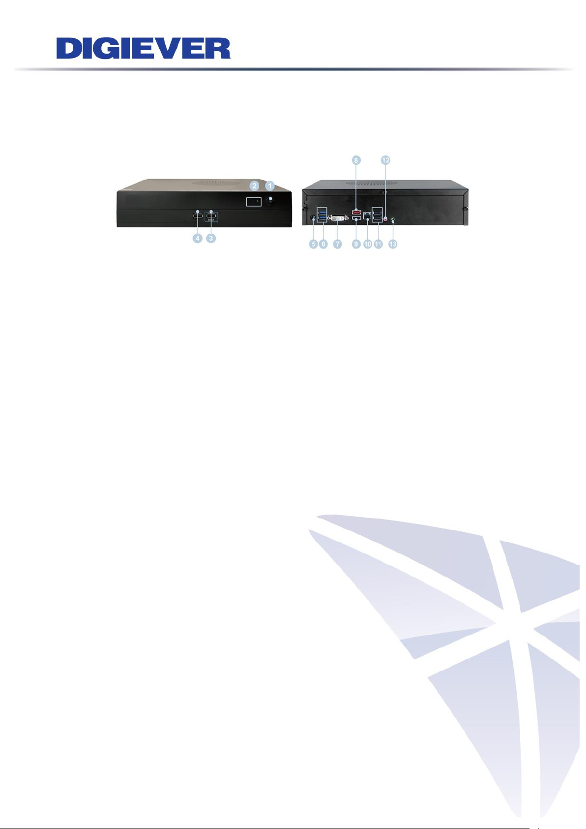
1.1.4 DS-2100 Pro Series
DS-2105 Pro/ DS-2109 Pro/ DS-2112 Pro/ DS-2116 Pro/ DS-2120 Pro/ DS-2125 Pro/
DS-2132 Pro/ DS-2136 Pro
Figure 1-4. Front & Rear View of DS-2100 Pro Series
1. Power button
2. LED indicators: HDD
3. USB 2.0 x1 (Support auto video backup)
4. USB 2.0 x1
5. Power connector
6. USB 3.0 x 2
7. DVI-I
8. eSATA x 1
9. HDMI x 1
10. Gigabit LAN
11. USB 2.0 x 2
12. Audio mic input (reserved)
13. Audio output (reserved)
5
Page 13
1.1.5 DS-4200 Pro Series
DS-4205 Pro/ DS-4209 Pro/ DS-4212 Pro/ DS-4216 Pro/ DS-4220 Pro/ DS-4225 Pro/
DS-4232 Pro/ DS-4236 Pro
Figure 1-5. Front & Rear View of DS-4200 Pro Series
1. LED indicators: LAN1, LAN2, eSATA, HDD1, HDD2, HDD3, HDD4
2. Power button
3. USB BACKUP button - Auto video backup
4. USB 2.0 x 1(Support auto video backup)
5. USB 2.0 x 1
6. HDD1
7. HDD2
8. HDD3
9. HDD4
10. Gigabit LAN x 2
11. USB 2.0 x 4
12. eSATA x 2
13. VGA output
14. HDMI output
15. DI/DO (4 in 2 out)
Top to bottom: Vcc5V, GND, DI-1, DI-2, DI-3, DI-4, DO-1, DO-2
16. Reset button*
17. Power connector
18. K-lock security slot
6
Page 14
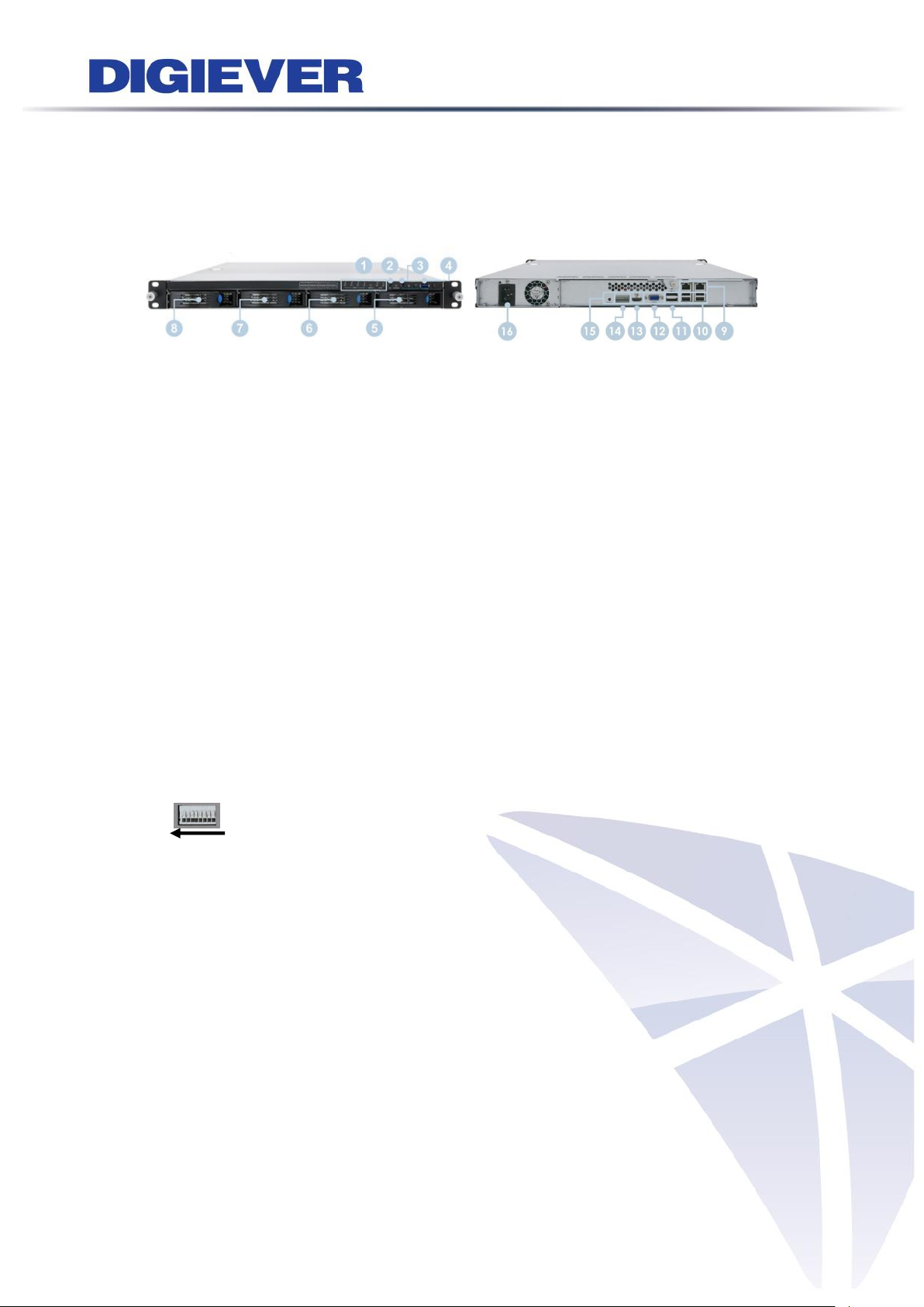
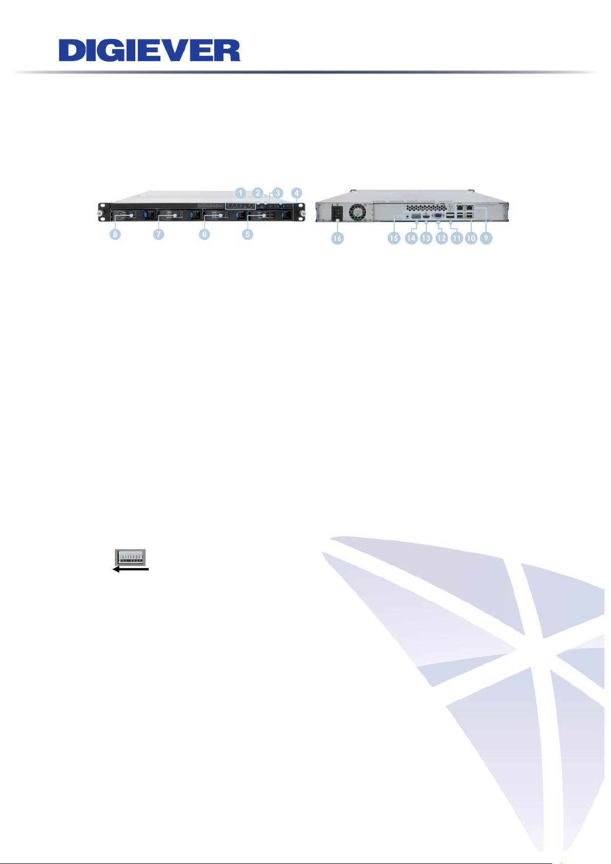
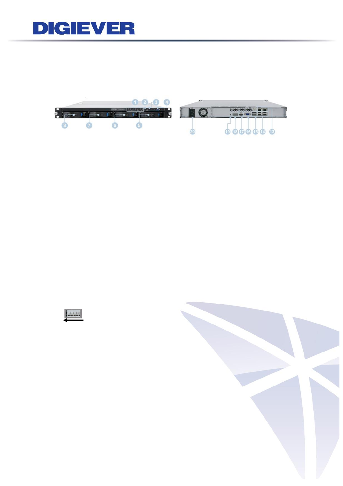
1.1.6 DS-4200-RM Pro Series
DS-4209-RM Pro/ DS-4212-RM Pro/ DS-4216-RM Pro/ DS-4220-RM Pro/
DS-4225-RM Pro/ DS-4232-RM Pro/ DS-4236-RM Pro
Figure 1-6. Front & Rear View of DS-4200-RM Pro Series
1. LED indicators: LAN1, LAN2, eSATA, HDD1, HDD2, HDD3, HDD4
2. Power button
3. USB BACKUP button - Auto video backup
4. USB 3.0 x 1 (Support auto video backup)
5. HDD1
6. HDD2
7. HDD3
8. HDD4
9. Gigabit LAN x 2
10. USB 2.0 x 4
11. eSATA x 2
12. VGA output
13. HDMI output
14. DI/DO (4 in 2 out)
Right to left: Vcc5V, GND, DI-1, DI-2, DI-3, DI-4, DO1, DO2
15. Reset button*
16. Power connector
7
Page 15
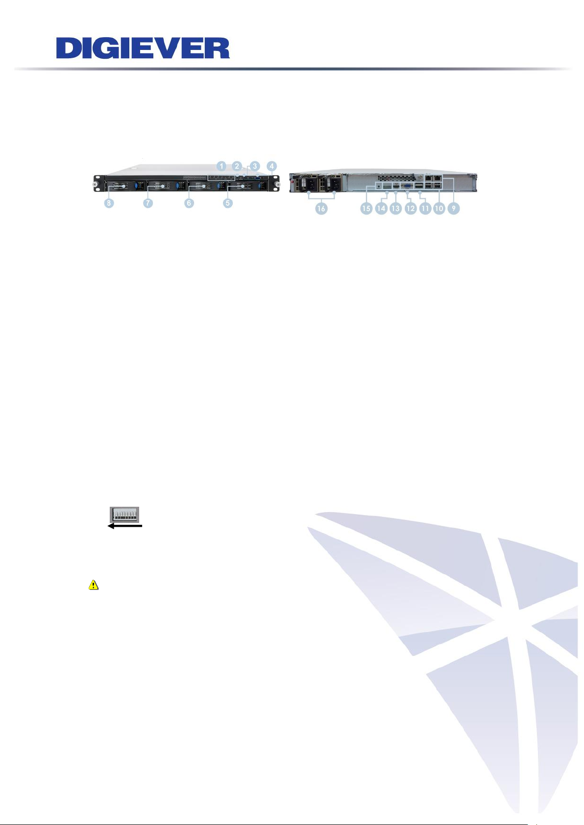
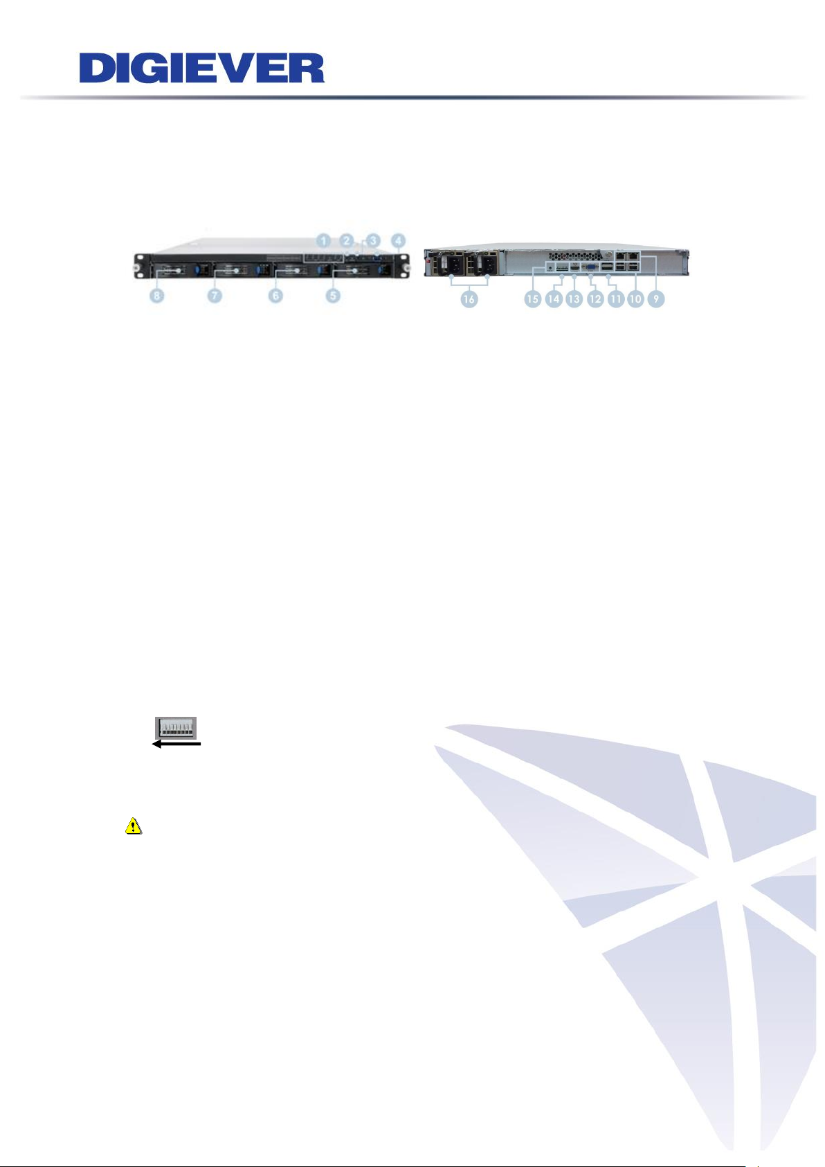
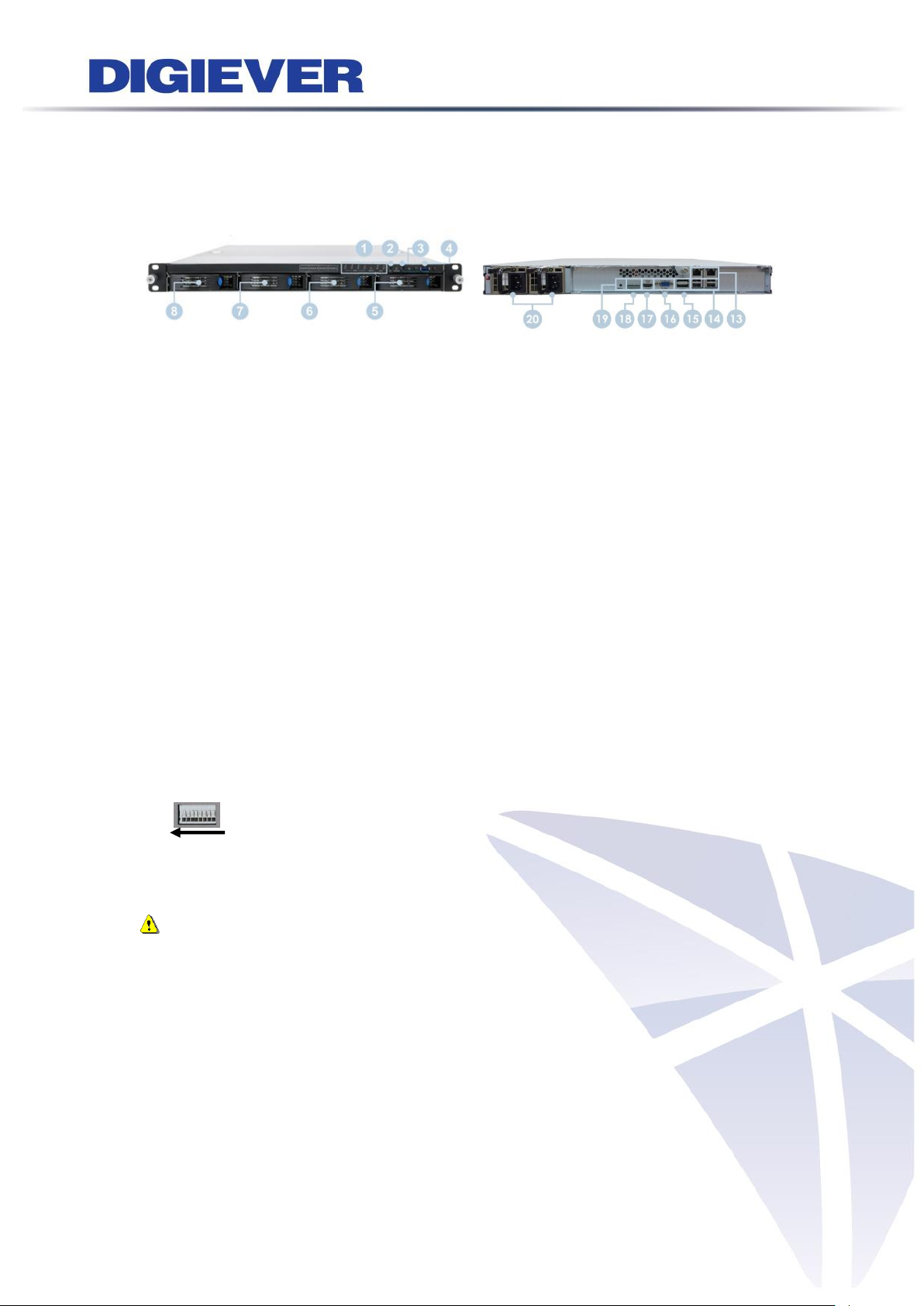
1.1.7 DS-4200-RMP Pro Series
DS-4209-RMP Pro/ DS-4212-RMP Pro/ DS-4216-RMP Pro/ DS-4220-RMP Pro/
DS-4225-RMP Pro/ DS-4232-RMP Pro/ DS-4236-RMP Pro
Figure 1-7. Front & Rear View of DS-4200-RMP Pro Series
1. LED indicators: LAN1, LAN2, eSATA, HDD1, HDD2, HDD3, HDD4
2. Power button
3. USB BACKUP button - Auto video backup
4. USB 3.0 x 1 (Support auto video backup)
5. HDD1
6. HDD2
7. HDD3
8. HDD4
9. Gigabit LAN x 2
10. USB 2.0 x 4
11. eSATA x 2
12. VGA output
13. HDMI output
14. DI/DO (4 in 2 out)
Right to left: Vcc5V, GND, DI-1, DI-2, DI-3, DI-4, DO1, DO2
15. Reset button*
16. Power connector
Note: The redundant power (with two adaptors) will be indicated in green light
in the rear panel of DS-4200-RMP Pro series. Once one of the adaptors is failed,
system buzzer will start beeping and no LED indicator light will display in rear
panel. To stop the buzzer, please press the red button in the rear panel of
system.
8
Page 16
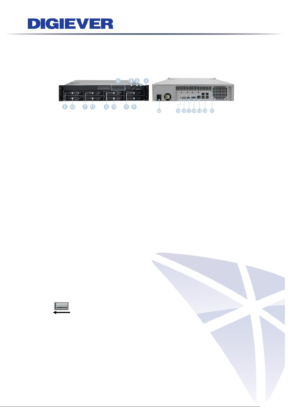
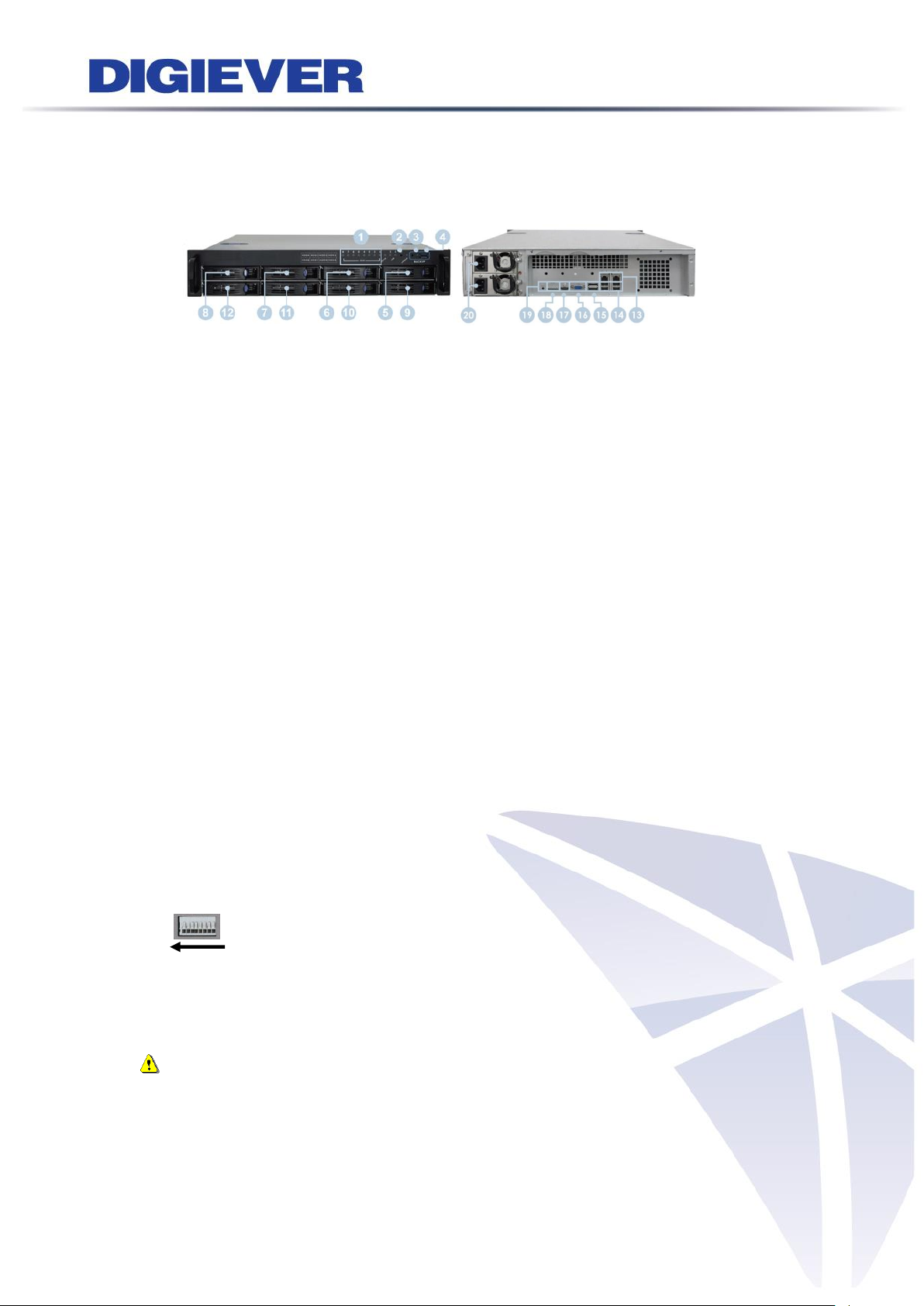
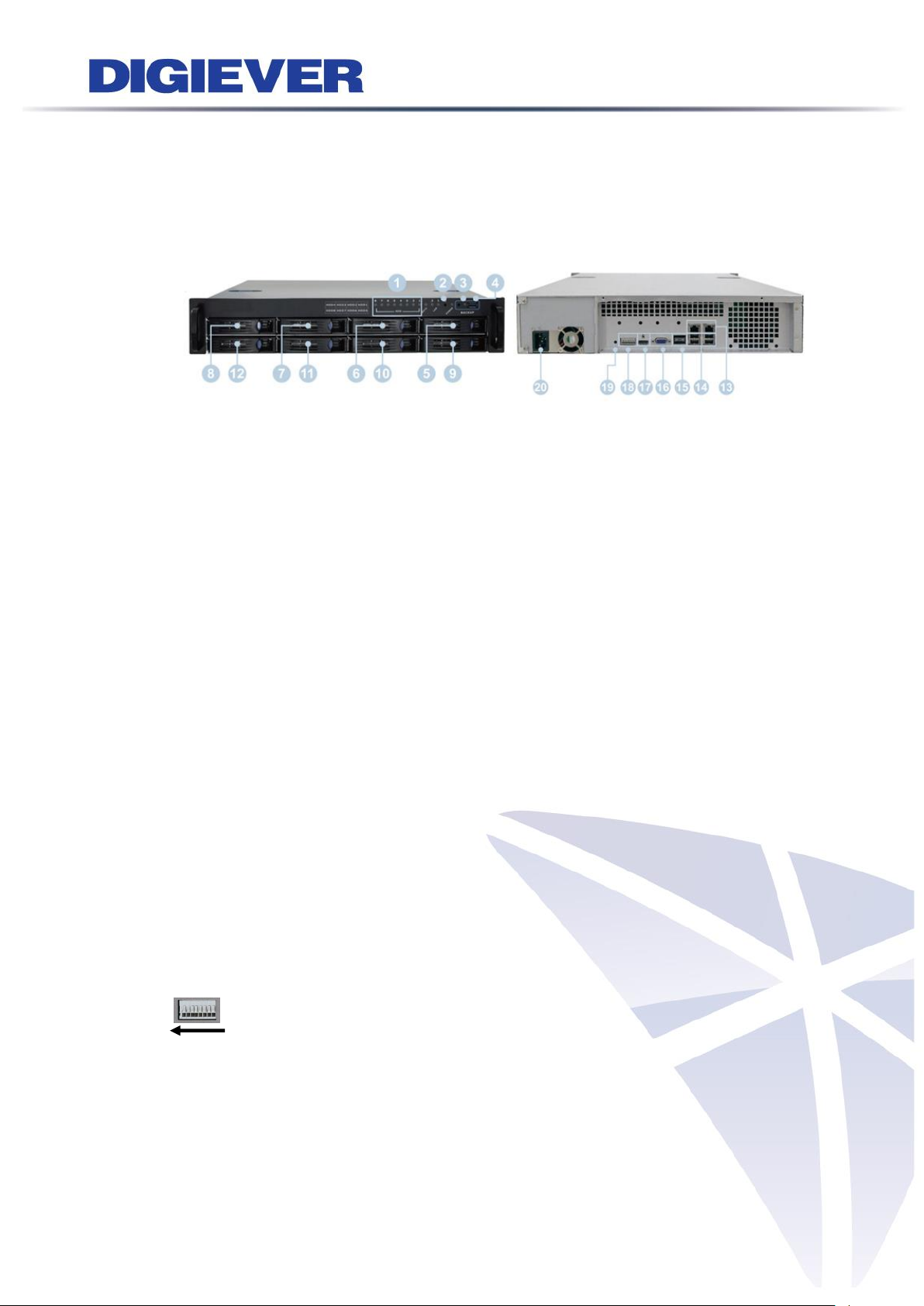
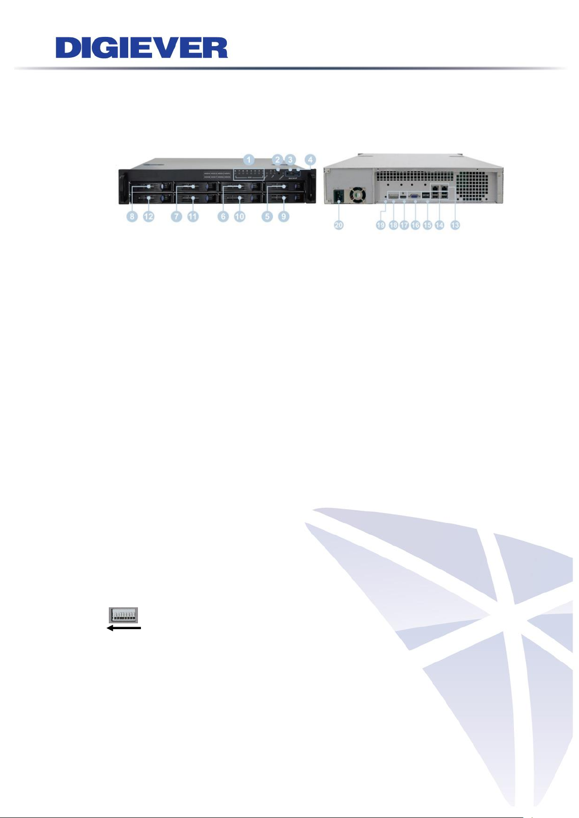
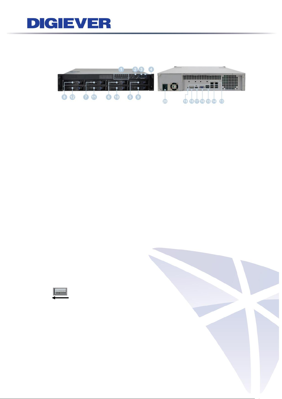
1.1.8 DS-8200-RM Pro Series
DS-8209-RM Pro/ DS-8212-RM Pro/ DS-8216-RM Pro/ DS-8220-RM Pro/
DS-8225-RM Pro/ DS-8232-RM Pro/ DS-8236-RM Pro
Figure 1-8. Front & Rear View of DS-8200-RM Pro Series
1. LED indicators: LAN1, LAN2, eSATA, HDD1, HDD2, HDD3, HDD4, HDD5, HDD6,
HDD7, HDD8
2. Power button
3. USB BACKUP button - Auto video backup
4. USB 3.0 x 1 (Support auto video backup)
5. HDD1
6. HDD2
7. HDD3
8. HDD4
9. HDD5
10. HDD6
11. HDD7
12. HDD8
13. Gigabit LAN x 2
14. USB 2.0 x 4
15. eSATA x 2
16. VGA output
17. HDMI output
18. DI/DO (4 in 2 out)
Right to left: Vcc5V, GND, DI-1, DI-2, DI-3, DI-4, DO1, DO2
19. Reset button*
20. Power connector
9
Page 17
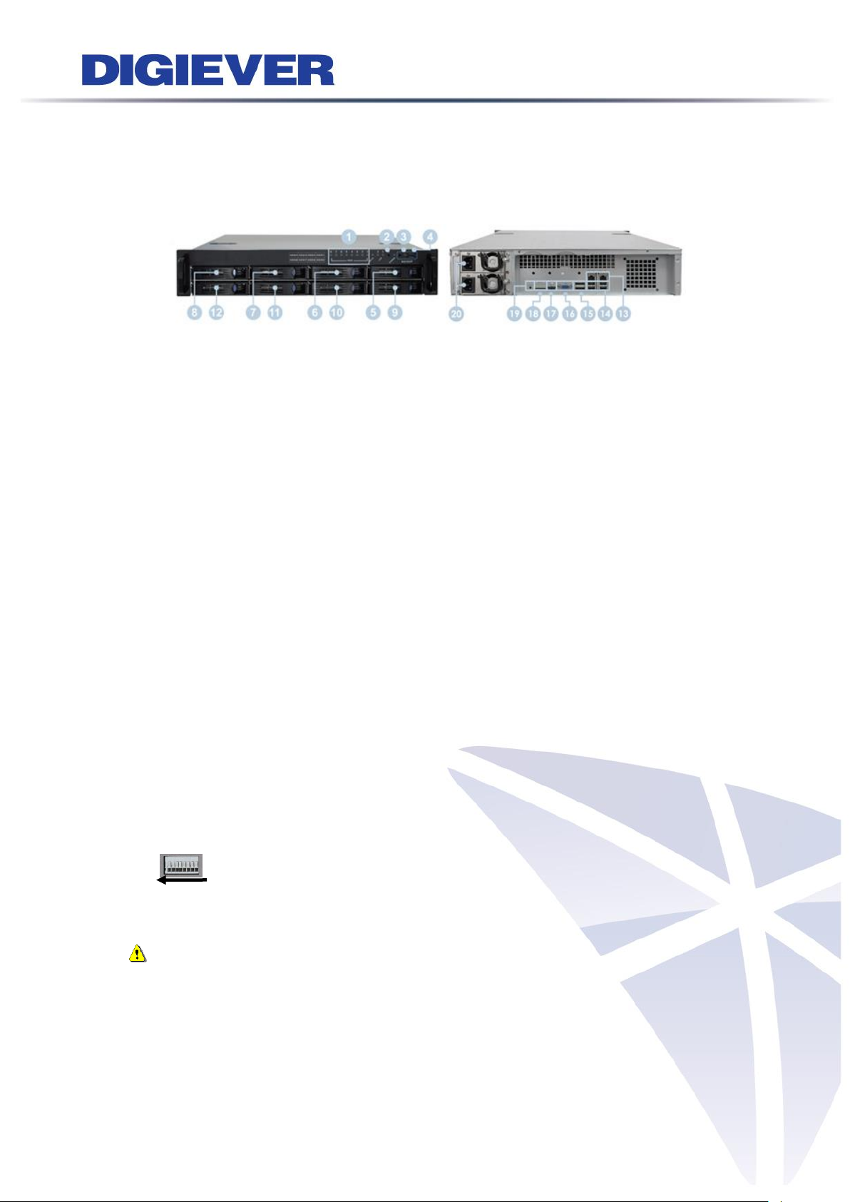
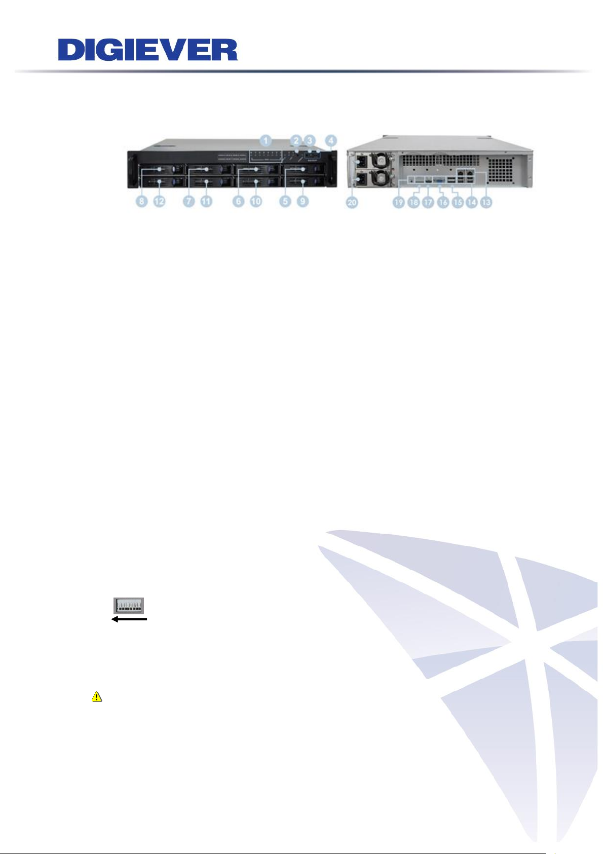
1.1.9 DS-8200-RMP Pro Series
DS-8209-RMP Pro/ DS-8212-RMP Pro/ DS-8216-RMP Pro/ DS-8220-RMP Pro/
DS-8225-RMP Pro/ DS-8232-RMP Pro/ DS-8236-RMP Pro
Figure 1-9. Front & Rear View of DS-8200-RMP Pro Series
1. LED indicators: LAN1, LAN2, eSATA, HDD1, HDD2, HDD3, HDD4, HDD5, HDD6,
HDD7, HDD8
2. Power button
3. USB BACKUP button - Auto video backup
4. USB 3.0 x 1 (Support auto video backup)
5. HDD1
6. HDD2
7. HDD3
8. HDD4
9. HDD5
10. HDD6
11. HDD7
12. HDD8
13. Gigabit LAN x 2
14. USB 2.0 x 4
15. eSATA x 2
16. VGA output
17. HDMI output
18. DI/DO (4 in 2 out)
Right to left: Vcc5V, GND, DI-1, DI-2, DI-3, DI-4, DO1, DO2
19. Reset button*
20. Power connector
Note: The redundant power (with two adaptors) will be indicated in green light
in the rear panel of DS-8200-RMP Pro series. Once one of the adaptors is failed,
system buzzer will start beeping and no LED indicator light will display in rear
panel. To stop the buzzer, please press the red button in the rear panel of
system.
10
Page 18

1.1.10 DS-1100 Pro+ Series
DS-1105 Pro+/ DS-1109 Pro+/ DS-1112 Pro+/ DS-1116 Pro+/ DS-1120 Pro+/
DS-1125 Pro+/ DS-1132 Pro+/ DS-1136 Pro+/ DS-1142 Pro+/ DS-1149 Pro+/
DS-1156 Pro+/ DS-1164 Pro+
Figure 1-10. Front & Rear View of DS-1100 Pro+ Series
1. Power button
2. LED indicators: HDD
3. USB 2.0 x1 (Support auto video backup)
4. USB 2.0 x1
5. Power connector
6. USB 3.0 x 2
7. DVI-I
8. eSATA x 1
9. HDMI x 1
10. Gigabit LAN
11. USB 2.0 x 2
12. Audio mic input (reserved)
13. Audio output (reserved)
11
Page 19
1.1.11 DS-2100 Pro+ Series
DS-2105 Pro+/ DS-2109 Pro+/ DS-2112 Pro+/ DS-2116 Pro+/ DS-2120 Pro+/
DS-2125 Pro+/ DS-2132 Pro+/ DS-2136 Pro+/ DS-2142 Pro+/ DS-2149 Pro+/
DS-2156 Pro+/ DS-2164 Pro+
Figure 1-11. Front & Rear View of DS-2100 Pro+ Series
1. Power button
2. LED indicators: HDD
3. USB 2.0 x1 (Support auto video backup)
4. USB 2.0 x1
5. Power connector
6. USB 3.0 x 2
7. DVI-I
8. eSATA x 1
9. HDMI x 1
10. Gigabit LAN
11. USB 2.0 x 2
12. Audio mic input (reserved)
13. Audio output (reserved)
12
Page 20

1.1.12 DS-4200 Pro+ Series
DS-4205 Pro+/ DS-4209 Pro+/ DS-4212 Pro+/ DS-4216 Pro+/ DS-4220 Pro+/
DS-4225 Pro+/ DS-4232 Pro+/ DS-4236 Pro+/ DS-4242 Pro+/ DS-4249 Pro+/
DS-4256 Pro+/ DS-4264 Pro+
Figure 1-12. Front & Rear View of DS-4200 Pro+ Series
1. LED indicators: LAN1, LAN2, eSATA, HDD1, HDD2, HDD3, HDD4
2. Power button
3. USB BACKUP button - Auto video backup
4. USB 2.0 x 1(Support auto video backup)
5. USB 2.0 x 1
6. HDD1
7. HDD2
8. HDD3
9. HDD4
10. Gigabit LAN x 2
11. USB 2.0 x 4
12. eSATA x 2
13. VGA output
14. HDMI output
15. DI/DO (4 in 2 out)
Top to bottom: Vcc5V, GND, DI-1, DI-2, DI-3, DI-4, DO-1, DO-2
16. Reset button*
17. Power connector
18. K-lock security slot
13
Page 21
1.1.13 DS-4200-RM Pro+ Series
DS-4209-RM Pro+/ DS-4212-RM Pro+/ DS-4216-RM Pro+/ DS-4220-RM Pro+/
DS-4225-RM Pro+/ DS-4232-RM Pro+/ DS-4236-RM Pro+/ DS-4242-RM Pro+/
DS-4249-RM Pro+/ DS-4256-RM Pro+/ DS-4264-RM Pro+
Figure 1-13. Front & Rear View of DS-4200-RM Pro+ Series
1. LED indicators: LAN1, LAN2, eSATA, HDD1, HDD2, HDD3, HDD4
2. Power button
3. USB BACKUP button - Auto video backup
4. USB 3.0 x 1 (Support auto video backup)
5. HDD1
6. HDD2
7. HDD3
8. HDD4
9. Gigabit LAN x 2
10. USB 2.0 x 4
11. eSATA x 2
12. VGA output
13. HDMI output
14. DI/DO (4 in 2 out)
Right to left: Vcc5V, GND, DI-1, DI-2, DI-3, DI-4, DO1, DO2
15. Reset button*
16. Power connector
14
Page 22
1.1.14 DS-4200-RMP Pro+ Series
DS-4209-RMP Pro+/ DS-4212-RMP Pro+/ DS-4216-RMP Pro+/ DS-4220-RMP Pro+/
DS-4225-RMP Pro+/ DS-4232-RMP Pro+/ DS-4236-RMP Pro+/ DS-4242-RMP Pro+/
DS-4249-RMP Pro+/ DS-4256-RMP Pro+/ DS-4264-RMP Pro+
Figure 1-14. Front & Rear View of DS-4200-RMP Pro+ Series
1. LED indicators: LAN1, LAN2, eSATA, HDD1, HDD2, HDD3, HDD4
2. Power button
3. USB BACKUP button - Auto video backup
4. USB 3.0 x 1 (Support auto video backup)
5. HDD1
6. HDD2
7. HDD3
8. HDD4
9. Gigabit LAN x 2
10. USB 2.0 x 4
11. eSATA x 2
12. VGA output
13. HDMI output
14. DI/DO (4 in 2 out)
Right to left: Vcc5V, GND, DI-1, DI-2, DI-3, DI-4, DO1, DO2
15. Reset button*
16. Power connector
Note: The redundant power (with two adaptors) will be indicated in green light
in the rear panel of DS-4200-RMP Pro+ series. Once one of the adaptors is failed,
system buzzer will start beeping and no LED indicator light will display in rear
panel. To stop the buzzer, please press the red button in the rear panel of
system.
15
Page 23
1.1.15 DS-8200-RM Pro+ Series
DS-8209-RM Pro+/ DS-8212-RM Pro+/ DS-8216-RM Pro+/ DS-8220-RM Pro+/
DS-8225-RM Pro+/ DS-8232-RM Pro+/ DS-8236-RM Pro+/ DS-8242-RM Pro+/
DS-8249-RM Pro+/ DS-8256-RM Pro+/ DS-8264-RM Pro+
Figure 1-15. Front & Rear View of DS-8200-RM Pro+ Series
1. LED indicators: LAN1, LAN2, eSATA, HDD1, HDD2, HDD3, HDD4, HDD5, HDD6,
HDD7, HDD8
2. Power button
3. USB BACKUP button - Auto video backup
4. USB 3.0 x 1 (Support auto video backup)
5. HDD1
6. HDD2
7. HDD3
8. HDD4
9. HDD5
10. HDD6
11. HDD7
12. HDD8
13. Gigabit LAN x 2
14. USB 2.0 x 4
15. eSATA x 2
16. VGA output
17. HDMI output
18. DI/DO (4 in 2 out)
Right to left: Vcc5V, GND, DI-1, DI-2, DI-3, DI-4, DO1, DO2
19. Reset button*
20. Power connector
16
Page 24
1.1.16 DS-8200-RMP Pro+ Series
DS-8209-RMP Pro+/ DS-8212-RMP Pro+/ DS-8216-RMP Pro+/ DS-8220-RMP Pro+/
DS-8225-RMP Pro+/ DS-8232-RMP Pro+/ DS-8236-RMP Pro+/ DS-8242-RMP Pro+/
DS-8249-RMP Pro+/ DS-8256-RMP Pro+/ DS-8264-RMP Pro+
Figure 1-16. Front & Rear View of DS-8200-RMP Pro+ Series
1. LED indicators: LAN1, LAN2, eSATA, HDD1, HDD2, HDD3, HDD4, HDD5, HDD6,
HDD7, HDD8
2. Power button
3. USB BACKUP button - Auto video backup
4. USB 3.0 x 1 (Support auto video backup)
5. HDD1
6. HDD2
7. HDD3
8. HDD4
9. HDD5
10. HDD6
11. HDD7
12. HDD8
13. Gigabit LAN x 2
14. USB 2.0 x 4
15. eSATA x 2
16. VGA output
17. HDMI output
18. DI/DO (4 in 2 out)
Right to left: Vcc5V, GND, DI-1, DI-2, DI-3, DI-4, DO1, DO2
19. Reset button*
20. Power connector
Note: The redundant power (with two adaptors) will be indicated in green light
in the rear panel of DS-8200-RMP Pro+ series. Once one of the adaptors is failed,
system buzzer will start beeping and no LED indicator light will display in rear
panel. To stop the buzzer, please press the red button in the rear panel of
system.
17
Page 25

1.1.17 DS-4300 Pro+ Series
DS-4332 Pro+/ DS-4336 Pro+/ DS-4342 Pro+/ DS-4349 Pro+/ DS-4356 Pro+/
DS-4364 Pro+
Figure 1-17. Front & Rear View of DS-4300 Pro+ Series
1. LED indicators: LAN1, LAN2, eSATA, HDD1, HDD2, HDD3, HDD4
2. Power button
3. USB BACKUP button - Auto video backup
4. USB 2.0 x 1(Support auto video backup)
5. USB 2.0 x 1
6. HDD1
7. HDD2
8. HDD3
9. HDD4
10. Gigabit LAN x 2
11. USB 2.0 x 4
12. eSATA x 2
13. VGA output
14. HDMI output
15. DI/DO (4 in 2 out)
Top to bottom: Vcc5V, GND, DI-1, DI-2, DI-3, DI-4, DO-1, DO-2
16. Reset button*
17. Power connector
18. K-lock security slot
18
Page 26
1.1.18 DS-4300-RM Pro+ Series
DS-4332-RM Pro+/ DS-4336-RM Pro+/ DS-4342-RM Pro+/ DS-4349-RM Pro+/
DS-4356-RM Pro+/ DS-4364-RM Pro+
Figure 1-18. Front & Rear View of DS-4300-RM Pro+ Series
1. LED indicators: LAN1, LAN2, eSATA, HDD1, HDD2, HDD3, HDD4
2. Power button
3. USB BACKUP button - Auto video backup
4. USB 3.0 x 1 (Support auto video backup)
5. HDD1
6. HDD2
7. HDD3
8. HDD4
9. Gigabit LAN x 2
10. USB 2.0 x 4
11. eSATA x 2
12. VGA output
13. HDMI output
14. DI/DO (4 in 2 out)
Right to left: Vcc5V, GND, DI-1, DI-2, DI-3, DI-4, DO1, DO2
15. Reset button*
16. Power connector
19
Page 27
1.1.19 DS-4300-RMP Pro+ Series
DS-4332-RMP Pro+/ DS-4336-RMP Pro+/ DS-4342-RMP Pro+/ DS-4349-RMP Pro+/
DS-4356-RMP Pro+/ DS-4364-RMP Pro+
Figure 1-19. Front & Rear View of DS-4300-RMP Pro+ Series
1. LED indicators: LAN1, LAN2, eSATA, HDD1, HDD2, HDD3, HDD4
2. Power button
3. USB BACKUP button - Auto video backup
4. USB 3.0 x 1 (Support auto video backup)
5. HDD1
6. HDD2
7. HDD3
8. HDD4
9. Gigabit LAN x 2
10. USB 2.0 x 4
11. eSATA x 2
12. VGA output
13. HDMI output
14. DI/DO (4 in 2 out)
Right to left: Vcc5V, GND, DI-1, DI-2, DI-3, DI-4, DO1, DO2
15. Reset button*
16. Power connector
Note: The redundant power (with two adaptors) will be indicated in green light
in the rear panel of DS-4300-RMP Pro+ series. Once one of the adaptors is failed,
system buzzer will start beeping and no LED indicator light will display in rear
panel. To stop the buzzer, please press the red button in the rear panel of
system.
20
Page 28
1.1.20 DS-8300-RM Pro+ Series
DS-8342-RM Pro+/ DS-8349-RM Pro+/ DS-8356-RM Pro+/ DS-8364-RM Pro+
Figure 1-20. Front & Rear View of DS-8300-RM Pro+ Series
1. LED indicators: LAN1, LAN2, eSATA, HDD1, HDD2, HDD3, HDD4, HDD5, HDD6,
HDD7, HDD8
2. Power button
3. USB BACKUP button - Auto video backup
4. USB 3.0 x 1 (Support auto video backup)
5. HDD1
6. HDD2
7. HDD3
8. HDD4
9. HDD5
10. HDD6
11. HDD7
12. HDD8
13. Gigabit LAN x 2
14. USB 2.0 x 4
15. eSATA x 2
16. VGA output
17. HDMI output
18. DI/DO (4 in 2 out)
Right to left: Vcc5V, GND, DI-1, DI-2, DI-3, DI-4, DO1, DO2
19. Reset button*
20. Power connector
21
Page 29
1.1.21 DS-8300-RMP Pro+ Series
DS-8342-RMP Pro+/ DS-8349-RMP Pro+/ DS-8356-RMP Pro+/ DS-8364-RMP Pro+
Figure 1-21. Front & Rear View of DS-8300-RMP Pro+ Series
1. LED indicators: LAN1, LAN2, eSATA, HDD1, HDD2, HDD3, HDD4, HDD5, HDD6,
HDD7, HDD8
2. Power button
3. USB BACKUP button - Auto video backup
4. USB 3.0 x 1 (Support auto video backup)
5. HDD1
6. HDD2
7. HDD3
8. HDD4
9. HDD5
10. HDD6
11. HDD7
12. HDD8
13. Gigabit LAN x 2
14. USB 2.0 x 4
15. eSATA x 2
16. VGA output
17. HDMI output
18. DI/DO (4 in 2 out)
Right to left: Vcc5V, GND, DI-1, DI-2, DI-3, DI-4, DO1, DO2
19. Reset button*
20. Power connector
Note: The redundant power (with two adaptors) will be indicated in green light
in the rear panel of DS-8300-RMP Pro+ series. Once one of the adaptors is failed,
system buzzer will start beeping and no LED indicator light will display in rear
panel. To stop the buzzer, please press the red button in the rear panel of
system.
22
Page 30
1.1.22 DS-8400-RM Pro+ Series
DS-8442-RM Pro+/ DS-8449-RM Pro+/ DS-8456-RM Pro+/ DS-8464-RM Pro+
Figure 1-22. Front & Rear View of DS-8400-RM Pro+ Series
1. LED indicators: LAN1, LAN2, eSATA, HDD1, HDD2, HDD3, HDD4, HDD5, HDD6,
HDD7, HDD8
2. Power button
3. USB BACKUP button - Auto video backup
4. USB 3.0 x 1 (Support auto video backup)
5. HDD1
6. HDD2
7. HDD3
8. HDD4
9. HDD5
10. HDD6
11. HDD7
12. HDD8
13. Gigabit LAN x 2
14. USB 2.0 x 4
15. eSATA x 2
16. VGA output
17. HDMI output
18. DI/DO (4 in 2 out)
Right to left: Vcc5V, GND, DI-1, DI-2, DI-3, DI-4, DO1, DO2
19. Reset button*
20. Power connector
23
Page 31

1.1.23 DS-16200-RM Pro+ Series
DS-16216-RM Pro+/ DS-16220-RM Pro+/ DS-16225-RM Pro+/ DS-16232-RM Pro+/
DS-16236-RM Pro+
Figure 1-23. Front & Rear View of DS-16200-RM Pro+ Series
1. LED indicators: LAN1, LAN2, eSATA, HDD1~16
2. Power button
3. USB BACKUP button - Auto video backup
4. USB 2.0 x 1 (Support auto video backup)
5. HDD1
6. HDD2
7. HDD3
8. HDD4
9. HDD5
10. HDD6
11. HDD7
12. HDD8
13. HDD9
14. HDD10
15. HDD11
16. HDD12
17. HDD13
18. HDD14
19. HDD15
20. HDD16
21. Gigabit LAN x 2
22. USB 2.0 x 4
23. eSATA x 2
24. VGA output
25. HDMI output
24
Page 32

26. DI/DO (4 in 2 out)
Right to left: Vcc5V, GND, DI-1, DI-2, DI-3, DI-4, DO1, DO2
27. Reset button*
28. Power connector
29. Power switch
1.1.24 DS-16300-RM Pro+ Series
DS-16316-RM Pro+/ DS-16320-RM Pro+/ DS-16325-RM Pro+/ DS-16332-RM Pro+/
DS-16336-RM Pro+/ DS-16342-RM Pro+/ DS-16349-RM Pro+/ DS-16356-RM Pro+/
DS-16364-RM Pro+
Figure 1-24. Front & Rear View of DS-16300-RM Pro+ Series
1. LED indicators: LAN1, LAN2, eSATA, HDD1~16
2. Power button
3. USB BACKUP button - Auto video backup
4. USB 2.0 x 1 (Support auto video backup)
5. HDD1
6. HDD2
7. HDD3
8. HDD4
9. HDD5
10. HDD6
11. HDD7
12. HDD8
13. HDD9
14. HDD10
15. HDD11
16. HDD12
17. HDD13
18. HDD14
19. HDD15
25
Page 33

20. HDD16
21. Gigabit LAN x 2
22. USB 2.0 x 4
23. eSATA x 2
24. VGA output
25. HDMI output
26. DI/DO (4 in 2 out)
Right to left: Vcc5V, GND, DI-1, DI-2, DI-3, DI-4, DO1, DO2
27. Reset button*
28. Power connector
29. Power switch
1.1.25 DS-16400-RM Pro+ Series
DS-16442-RM Pro+/ DS-16449-RM Pro+/ DS-16456-RM Pro+/ DS-16464-RM Pro+
Figure 1-25. Front & Rear View of DS-16400-RM Pro+ Series
1. LED indicators: LAN1, LAN2, eSATA, HDD1~16
2. Power button
3. USB BACKUP button - Auto video backup
4. USB 2.0 x 1 (Support auto video backup)
5. HDD1
6. HDD2
7. HDD3
8. HDD4
9. HDD5
10. HDD6
11. HDD7
12. HDD8
13. HDD9
14. HDD10
15. HDD11
26
Page 34

16. HDD12
17. HDD13
18. HDD14
19. HDD15
20. HDD16
21. Gigabit LAN x 2
22. USB 2.0 x 4
23. eSATA x 2
24. VGA output
25. HDMI output
26. DI/DO (4 in 2 out)
Right to left: Vcc5V, GND, DI-1, DI-2, DI-3, DI-4, DO1, DO2
27. Reset button*
28. Power connector
29. Power switch
1.1.26 DS-16500-RM Pro+ Series
DS-16542-RM Pro+/ DS-16549-RM Pro+/ DS-16556-RM Pro+/ DS-16564-RM Pro+
Figure 1-26. Front & Rear View of DS-16500-RM Pro+ Series
1. LED indicators: LAN1, LAN2, eSATA, HDD1~16
2. Power button
3. USB BACKUP button - Auto video backup
4. USB 2.0 x 1 (Support auto video backup)
5. HDD1
6. HDD2
7. HDD3
8. HDD4
9. HDD5
10. HDD6
11. HDD7
27
Page 35

12. HDD8
13. HDD9
14. HDD10
15. HDD11
16. HDD12
17. HDD13
18. HDD14
19. HDD15
20. HDD16
21. Gigabit LAN x 2
22. USB 2.0 x 4
23. eSATA x 2
24. VGA output
25. HDMI output
26. DI/DO (4 in 2 out)
Right to left: Vcc5V, GND, DI-1, DI-2, DI-3, DI-4, DO1, DO2
27. Reset button*
28. Power connector
29. Power switch
28
Page 36

1.1.27 MN-1100 Pro+ Series
MN-1105 Pro+/ MN-1109 Pro+/ MN-1112 Pro+/MN-1116 Pro+ /MN-1120 Pro+/
MN-1125 Pro+/ MN-1132 Pro+/ MN-1136 Pro+
Figure 1-27. Front & Rear View of MN-1100 Pro+ Series
1. LED indicators
2. Power SW (Bypass Ignition)
3. 2.5” Removable HDD tray x 1
4. Gigabit LAN x 4
5. USB 2.0 x 4
6. Antenna port x4
7. DI/DO port
8. HDMI x 1
9. DVI-D x 1(Reserved)
10. VGA x 1
11. 12V DC power output
12. 9~36 DC power input
13. COM x2
29
Page 37

1.1.28 MN-2100 Pro+ Series
MN-2105 Pro+/ MN-2109 Pro+/ MN-2112 Pro+/MN-2116 Pro+ /MN-2120 Pro+/
MN-2125 Pro+/ MN-2132 Pro+/ MN-2136 Pro+
Figure 1-28. Front & Rear View of MN-2100 Pro+ Series
1. LED indicators
2. Power SW (Bypass Ignition)
3. 2.5” Removable HDD tray x 1
4. Gigabit LAN x 4
5. USB 2.0 x 4
6. Antenna port x4
7. DI/DO port
8. HDMI x 1
9. DVI-D x 1(Reserved)
10. VGA x 1
11. 12V DC power output
12. 9~36 DC power input
13. COM x2
30
Page 38

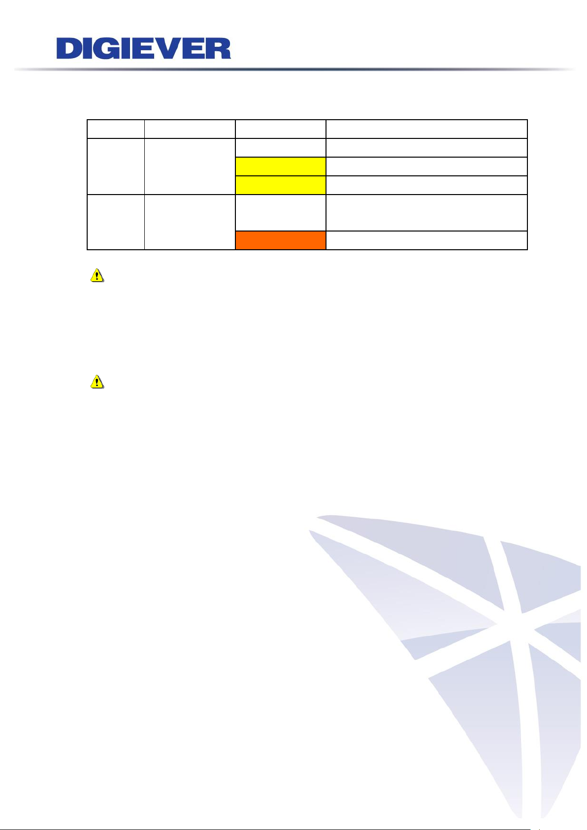
LED on Front Panel
LED
LED Color & Status
Indicate
LAN
Off
LAN Link is not established
Orange
LAN Link is established
Orange blinking
LAN is being accessed
eSATA
Off
No data transmission
Orange blinking
The eSATA device is being accessed
HDD1
HDD2
Off
Hard disk drive device is not established
Green
Hard disk drive is ready to be accessed
Green blinking
Hard disk drive data is being accessed
Red blinking
Hard disk drive error and need to be checked
Red
Hard disk drive failure and need to be removed
Power
Off
Power Off
Green
Power On
BACKUP
Off
USB device is not detected
Blue
USB device is ready
Blue blinking
NVR data is being copied to the USB device
(Blinking with 1Hz)
Red
Backup error occurs
1.2 LED Indicators Status
1.2.1 DS-2000 Series
DS-2005/ DS-2009/ DS-2012/ DS-2016/ DS-2020/ DS-2025/ DS-2032
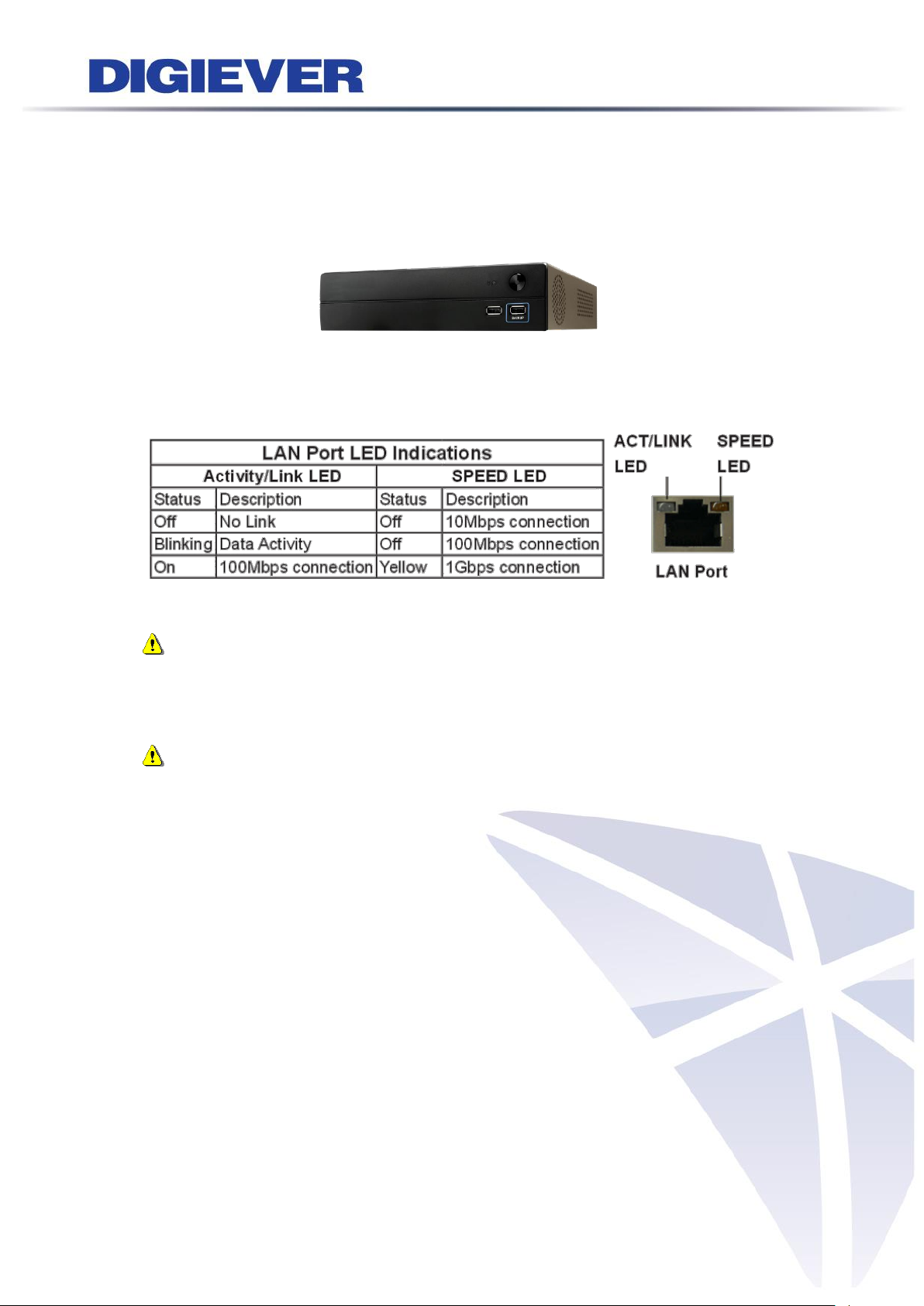
Figure 2-1. DS-2000 Series Front Panel & RJ-45 Port
31
Page 39
LED on RJ-45 Port on Rear Panel
LED
LED Position
LED Status
Indicate
LAN
Link/Activity
(Right LED)
Off
LAN Link is not established
Yellow
LAN Link is established
Yellow blinking
LAN Activity is occurring
LAN
Speed
(Left LED)
Off
10M/100Mbps connection or no
connection
Orange
1000Mbps connection
Note:
**USB BACKUP will beep and process after long pressing BACKUP button for 3
seconds.
**To turn off your NVR, long pressing power button at least 2 seconds.
**To turn on your NVR, long pressing power button at least 3 seconds.
Note: Once users press reset button, configuration of Camera Setting, Recording
Settings, Event & Action Setting, E-Mail Settings, and Server Settings will reset to
default. It is advised to backup system configurations. For more information, refer to
detail information in user manual 5.6.3 Save/Load Configuration.
32
Page 40

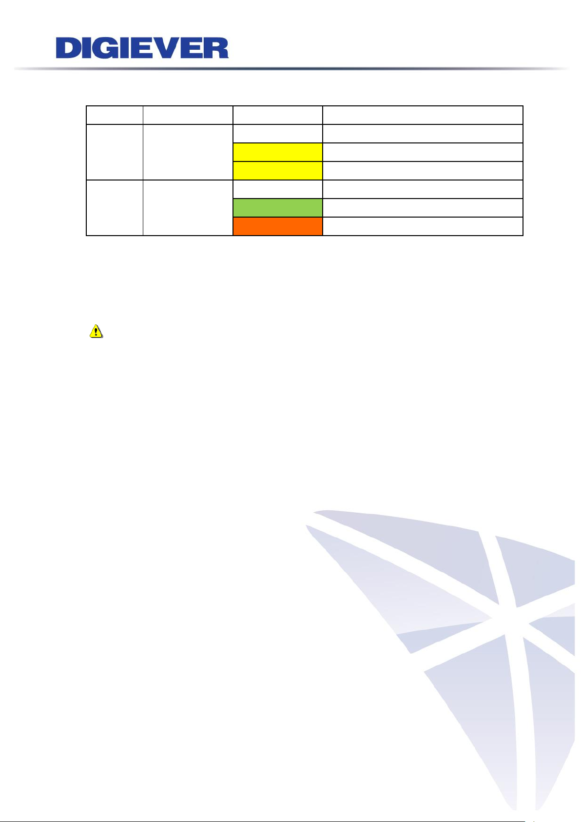
LED on Front Panel
LED
LED Color & Status
Indicate
LAN
Off
LAN Link is not established
Orange
LAN Link is established
Orange blinking
LAN is being accessed
eSATA
Off
No data transmission
Orange blinking
The eSATA device is being accessed
HDD1
HDD2
HDD3
HDD4
Off
Hard disk drive device is not established
Green
Hard disk drive is ready to be accessed
Green blinking
Hard disk drive data is being accessed
Red blinking
Hard disk drive error and need to be checked
Red
Hard disk drive failure and need to be removed
Power
Off
Power Off
Green
Power On
BACKUP
Off
USB device is not detected
Blue
USB device is ready
Blue blinking
NVR data is being copied to the USB device
(Blinking with 1Hz)
Red
Backup error occurs
1.2.2 DS-4000 Series
DS-4005/ DS-4009/ DS-4012/ DS-4016/ DS-4020/ DS-4025/ DS-4032
Figure 2-2. DS-4000 Series Front Panel & RJ-45 Port
33
Page 41

LED on RJ-45 Port on Rear Panel
LED
LED Position
LED Status
Indicate
LAN
Link/Activity
(Right LED)
Off
LAN Link is not established
Yellow
LAN Link is established
Yellow blinking
LAN Activity is occurring
LAN
Speed
(Left LED)
Off
10M/100Mbps connection or no
connection
Orange
1000Mbps connection
*USB BACKUP will start and beep after 3 seconds user presses BACKUP button.
**To turn off NVR, users need to press power button at least 2 seconds.
***To turn on NVR, users need to press power button at least 3 seconds.
Note: Once users press reset button, configuration of Camera Setting, Recording
Settings, Event & Action Setting, E-Mail Settings, and Server Settings will reset to
default. It is advised to backup system configurations. For more information, refer to
detail information in user manual 5.6.3 Save/Load Configuration.
34
Page 42
1.2.3 DS-1100 Pro Series
DS-1105 Pro/ DS-1109 Pro/ DS-1112 Pro/ DS-1116 Pro/ DS-1120 Pro/ DS-1125 Pro/
DS-1132 Pro/ DS-1136 Pro
Figure 2-3. DS-1100 Pro Series Front Panel
Note:
**To turn off your NVR, long pressing power button at least 2 seconds.
**To turn on your NVR, long pressing power button at least 3 seconds.
Note: To reset to default, please refer to “NVR Hardware reset to default method”
in Chapter5 - 5.6.3 Save/Load Configuration. Once users press reset button,
configuration of Camera Setting, Recording Settings, Event & Action Setting, E-Mail
Settings, and Server Settings will reset to default. It is advised to backup system
configurations.
35
Page 43

1.2.4 DS-2100 Pro Series
DS-2105 Pro/ DS-2109 Pro/ DS-2112 Pro/ DS-2116 Pro/ DS-2120 Pro/ DS-2125 Pro/
DS-2132 Pro/ DS-2136 Pro
Figure 2-4. DS-2100 Series Front Panel
Note:
**To turn off your NVR, long pressing power button at least 2 seconds.
**To turn on your NVR, long pressing power button at least 3 seconds.
Note: To reset to default, please refer to “NVR Hardware reset to default method”
in Chapter5 - 5.6.3 Save/Load Configuration. Once users press reset button,
configuration of Camera Setting, Recording Settings, Event & Action Setting, E-Mail
Settings, and Server Settings will reset to default. It is advised to backup system
configurations.
36
Page 44

LED on Front Panel
LED
LED Color & Status
Indicate
LAN
Off
LAN Link is not established
Orange
LAN Link is established
Orange blinking
LAN is being accessed
eSATA
Off
No data transmission
Orange blinking
The eSATA device is being accessed
HDD1
HDD2
HDD3
HDD4
Off
Hard disk drive device is not established
Green
Hard disk drive is ready to be accessed
Green blinking
Hard disk drive data is being accessed
Red blinking
Hard disk drive error and need to be checked
Red
Hard disk drive failure and need to be removed
Power
Off
Power Off
Green
Power On
BACKUP
Off
USB device is not detected
Blue
USB device is ready
Blue blinking
NVR data is being copied to the USB device
(Blinking with 1Hz)
Red
Backup error occurs
1.2.5 DS-4200 Pro Series
DS-4205Pro/ DS-4209Pro/ DS-4212Pro/ DS-4216Pro/ DS-4220Pro/ DS-4225Pro/
DS-4232 Pro/ DS-4236 Pro
Figure 2-5. DS-4200 Pro Series Front Panel & RJ-45 Port
37
Page 45

LED on RJ-45 Connection at Rear Panel
LED
LED Position
LED/State
Indicate
LAN1
LAN2
Link/Activity
(Right LED)
Off
LAN Link is not established
Yellow
LAN Link is established
Yellow Blinking
LAN activity is occurring
LAN1
LAN2
Speed
(Left LED)
Off
10Mbps connection or no connection
Green
100Mbps connection
Orange
1000Mbps connection
*USB BACKUP will start and beep after 3 seconds user presses BACKUP button.
**To turn off NVR, user needs to press power button at least 2 seconds.
Note: Once users press reset button, configuration of Camera Setting, Recording
Settings, Event & Action Setting, E-Mail Settings, and Server Settings will reset to
default. It is advised to backup system configurations. For more information, refer to
detail information in user manual 5.6.3 Save/Load Configuration.
38
Page 46

LED on Front Panel
LED
LED Color & Status
Indicate
LAN
Off
LAN Link is not established
Orange
LAN Link is established
Orange blinking
LAN is being accessed
eSATA
Off
No data transmission
Orange blinking
The eSATA device is being accessed
HDD1
HDD2
HDD3
HDD4
Off
Hard disk drive device is not established
Green
Hard disk drive is ready to be accessed
Green blinking
Hard disk drive data is being accessed
Red blinking
Hard disk drive error and need to be checked
Red
Hard disk drive failure and need to be removed
Power
Off
Power Off
Green
Power On
BACKUP
Off
USB device is not detected
Blue
USB device is ready
Blue blinking
NVR data is being copied to the USB device
(Blinking with 1Hz)
Red
Backup error occurs
1.2.6 DS-4200-RM Pro Series
DS-4209-RM Pro/ DS-4212-RM Pro/ DS-4216-RM Pro/DS-4220-RM Pro/
DS-4225-RM Pro/ DS-4232-RM Pro/ DS-4236-RM Pro
Figure 2-6. Front View of DS-4200-RM Pro Series & RJ-45 Port
39
Page 47
LED on RJ-45 Connection at Rear Panel
LED
LED Position
LED/State
Indicate
LAN1
LAN2
Link/Activity
(Right LED)
Off
LAN Link is not established
Yellow
LAN Link is established
Yellow Blinking
LAN activity is occurring
LAN1
LAN2
Speed
(Left LED)
Off
10Mbps connection or no connection
Green
100Mbps connection
Orange
1000Mbps connection
*USB BACKUP will start and beep after 3 seconds user presses BACKUP button.
**To turn off NVR, user needs to press power button at least 2 seconds.
*** The LED in the HDD trays are reserved.
Note: Once users press reset button, configuration of Camera Setting, Recording
Settings, Event & Action Setting, E-Mail Settings, and Server Settings will reset to
default. It is advised to backup system configurations. For more information, refer to
detail information in user manual 5.6.3 Save/Load Configuration.
40
Page 48

LED on Front Panel
LED
LED Color & Status
Indicate
LAN
Off
LAN Link is not established
Orange
LAN Link is established
Orange blinking
LAN is being accessed
eSATA
Off
No data transmission
Orange blinking
The eSATA device is being accessed
HDD1
HDD2
HDD3
HDD4
Off
Hard disk drive device is not established
Green
Hard disk drive is ready to be accessed
Green blinking
Hard disk drive data is being accessed
Red blinking
Hard disk drive error and need to be checked
Red
Hard disk drive failure and need to be removed
Power
Off
Power Off
Green
Power On
BACKUP
Off
USB device is not detected
Blue
USB device is ready
Blue blinking
NVR data is being copied to the USB device
(Blinking with 1Hz)
Red
Backup error occurs
1.2.7 DS-4200-RMP Pro Series
DS-4209-RMP Pro/ DS-4212-RMP Pro/ DS-4216-RMP Pro/ DS-4220-RMP Pro/
DS-4225-RMP Pro/ DS-4232-RMP Pro/ DS-4236-RMP Pro
Figure 2-7. Front View of DS-4200-RMP Pro Series & RJ-45 Port
41
Page 49

LED on RJ-45 Connection at Rear Panel
LED
LED Position
LED/State
Indicate
LAN1
LAN2
Link/Activity
(Right LED)
Off
LAN Link is not established
Yellow
LAN Link is established
Yellow Blinking
LAN activity is occurring
LAN1
LAN2
Speed
(Left LED)
Off
10Mbps connection or no connection
Green
100Mbps connection
Orange
1000Mbps connection
*USB BACKUP will start and beep after 3 seconds user presses BACKUP button.
**To turn off NVR, user needs to press power button at least 2 seconds.
*** The LED in the HDD trays are reserved.
Note: Once users press reset button, configuration of Camera Setting, Recording
Settings, Event & Action Setting, E-Mail Settings, and Server Settings will reset to
default. It is advised to backup system configurations. For more information, refer to
detail information in user manual 5.6.3 Save/Load Configuration.
42
Page 50

LED on Front Panel
LED
LED Color & Status
Indicate
LAN
Off
LAN Link is not established
Orange
LAN Link is established
Orange blinking
LAN is being accessed
eSATA
Off
No data transmission
Orange blinking
The eSATA device is being accessed
HDD1
HDD2
HDD3
HDD4
HDD5
HDD6
HDD7
HDD8
Off
Hard disk drive device is not established
Green
Hard disk drive is ready to be accessed
Green blinking
Hard disk drive data is being accessed
Red blinking
Hard disk drive error and need to be checked
Red
Hard disk drive failure and need to be removed
Power
Off
Power Off
Green
Power On
BACKUP
Off
USB device is not detected
Blue
USB device is ready
Blue blinking
NVR data is being copied to the USB device
(Blinking with 1Hz)
Red
Backup error occurs
1.2.8 DS-8200-RM Pro Series
DS-8209-RM Pro/ DS-8212-RM Pro/ DS-8216-RM Pro/DS-8220-RM Pro/
DS-8225-RM Pro/DS-8232-RM Pro/ DS-8236-RM Pro
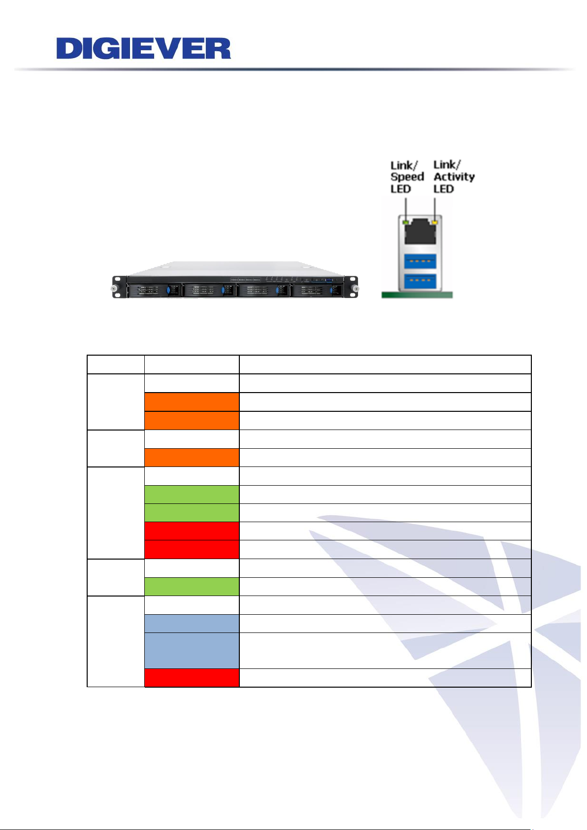
Figure 2-8. Front View of DS-8200-RM Pro Series & RJ-45 Port
43
Page 51

LED on RJ-45 Connection at Rear Panel
LED
LED Position
LED/State
Indicate
LAN1
LAN2
Link/Activity
(Right LED)
Off
LAN Link is not established
Yellow
LAN Link is established
Yellow Blinking
LAN activity is occurring
LAN1
LAN2
Speed
(Left LED)
Off
10Mbps connection or no connection
Green
100Mbps connection
Orange
1000Mbps connection
*USB BACKUP will start and beep after 3 seconds user presses BACKUP button.
**To turn off NVR, user needs to press power button at least 2 seconds.
*** The LED in the HDD trays are reserved.
Note: Once users press reset button, configuration of Camera Setting, Recording
Settings, Event & Action Setting, E-Mail Settings, and Server Settings will reset to
default. It is advised to backup system configurations. For more information, refer to
detail information in user manual 5.6.3 Save/Load Configuration.
44
Page 52

LED on Front Panel
LED
LED Color & Status
Indicate
LAN
Off
LAN Link is not established
Orange
LAN Link is established
Orange blinking
LAN is being accessed
eSATA
Off
No data transmission
Orange blinking
The eSATA device is being accessed
HDD1
HDD2
HDD3
HDD4
HDD5
HDD6
HDD7
HDD8
Off
Hard disk drive device is not established
Green
Hard disk drive is ready to be accessed
Green blinking
Hard disk drive data is being accessed
Red blinking
Hard disk drive error and need to be checked
Red
Hard disk drive failure and need to be removed
Power
Off
Power Off
Green
Power On
BACKUP
Off
USB device is not detected
Blue
USB device is ready
Blue blinking
NVR data is being copied to the USB device
(Blinking with 1Hz)
Red
Backup error occurs
1.2.9 DS-8200-RMP Pro Series
DS-8209-RMP Pro/ DS-8212-RMP Pro/ DS-8216-RMP Pro/DS-8220-RMP Pro/
DS-8225-RMP Pro/DS-8232-RMP Pro/ DS-8236-RMP Pro
Figure 2-9. Front View of DS-8200-RMP Pro Series & RJ-45 Port
45
Page 53

LED on RJ-45 Connection at Rear Panel
LED
LED Position
LED/State
Indicate
LAN1
LAN2
Link/Activity
(Right LED)
Off
LAN Link is not established
Yellow
LAN Link is established
Yellow Blinking
LAN activity is occurring
LAN1
LAN2
Speed
(Left LED)
Off
10Mbps connection or no connection
Green
100Mbps connection
Orange
1000Mbps connection
*USB BACKUP will start and beep after 3 seconds user presses BACKUP button.
**To turn off NVR, user needs to press power button at least 2 seconds.
*** The LED in the HDD trays are reserved.
Note: Once users press reset button, configuration of Camera Setting, Recording
Settings, Event & Action Setting, E-Mail Settings, and Server Settings will reset to
default. It is advised to backup system configurations. For more information, refer to
detail information in user manual 5.6.3 Save/Load Configuration.
46
Page 54

1.2.10 DS-1100 Pro+ Series
DS-1105 Pro+/ DS-1109 Pro+/ DS-1112 Pro+/ DS-1116 Pro+/ DS-1120 Pro+/
DS-1125 Pro+/ DS-1132 Pro+/ DS-1136 Pro+/ DS-1142 Pro+/ DS-1149 Pro+/
DS-1156 Pro+/ DS-1164 Pro+
Figure 2-10. DS-1100 Pro+ Series Front Panel
Note:
**To turn off your NVR, long pressing power button at least 2 seconds.
**To turn on your NVR, long pressing power button at least 3 seconds.
Note: To reset to default, please refer to “NVR Hardware reset to default method”
in Chapter5 - 5.6.3 Save/Load Configuration. Once users press reset button,
configuration of Camera Setting, Recording Settings, Event & Action Setting, E-Mail
Settings, and Server Settings will reset to default. It is advised to backup system
configurations.
47
Page 55

1.2.11 DS-2100 Pro+ Series
DS-2105 Pro+/ DS-2109 Pro+/ DS-2112 Pro+/ DS-2116 Pro+/ DS-2120 Pro+/
DS-2125 Pro+/ DS-2132 Pro+/ DS-2136 Pro+/ DS-2142 Pro+/ DS-2149 Pro+/
DS-2156 Pro+/ DS-2164 Pro+
Figure 2-11. DS-2100 Pro+ Series Front Panel
Note:
**To turn off your NVR, long pressing power button at least 2 seconds.
**To turn on your NVR, long pressing power button at least 3 seconds.
Note: To reset to default, please refer to “NVR Hardware reset to default method”
in Chapter5 - 5.6.3 Save/Load Configuration. Once users press reset button,
configuration of Camera Setting, Recording Settings, Event & Action Setting, E-Mail
Settings, and Server Settings will reset to default. It is advised to backup system
configurations.
48
Page 56

LED on Front Panel
LED
LED Color & Status
Indicate
LAN
Off
LAN Link is not established
Orange
LAN Link is established
Orange blinking
LAN is being accessed
eSATA
Off
No data transmission
Orange blinking
The eSATA device is being accessed
HDD1
HDD2
HDD3
HDD4
Off
Hard disk drive device is not established
Green
Hard disk drive is ready to be accessed
Green blinking
Hard disk drive data is being accessed
Red blinking
Hard disk drive error and need to be checked
Red
Hard disk drive failure and need to be removed
Power
Off
Power Off
Green
Power On
BACKUP
Off
USB device is not detected
Blue
USB device is ready
Blue blinking
NVR data is being copied to the USB device
(Blinking with 1Hz)
Red
Backup error occurs
1.2.12 DS-4200 Pro+ Series
DS-4205 Pro+/ DS-4209 Pro+/ DS-4212 Pro+/ DS-4216 Pro+/ DS-4220 Pro+/
DS-4225 Pro+/ DS-4232 Pro+/ DS-4236 Pro+/ DS-4242 Pro+/ DS-4249 Pro+/
DS-4256 Pro+/ DS-4264 Pro+
Figure 2-12. DS-4200 Pro+ Series Front Panel & RJ-45 Port
49
Page 57

LED on RJ-45 Connection at Rear Panel
LED
LED Position
LED/State
Indicate
LAN1
LAN2
Link/Activity
(Right LED)
Off
LAN Link is not established
Yellow
LAN Link is established
Yellow Blinking
LAN activity is occurring
LAN1
LAN2
Speed
(Left LED)
Off
10Mbps connection or no connection
Green
100Mbps connection
Orange
1000Mbps connection
*USB BACKUP will start and beep after 3 seconds user presses BACKUP button.
**To turn off NVR, user needs to press power button at least 2 seconds.
Note: Once users press reset button, configuration of Camera Setting, Recording
Settings, Event & Action Setting, E-Mail Settings, and Server Settings will reset to
default. It is advised to backup system configurations. For more information, refer to
detail information in user manual 5.6.3 Save/Load Configuration.
50
Page 58

LED on Front Panel
LED
LED Color & Status
Indicate
LAN
Off
LAN Link is not established
Orange
LAN Link is established
Orange blinking
LAN is being accessed
eSATA
Off
No data transmission
Orange blinking
The eSATA device is being accessed
HDD1
HDD2
HDD3
HDD4
Off
Hard disk drive device is not established
Green
Hard disk drive is ready to be accessed
Green blinking
Hard disk drive data is being accessed
Red blinking
Hard disk drive error and need to be checked
Red
Hard disk drive failure and need to be removed
Power
Off
Power Off
Green
Power On
BACKUP
Off
USB device is not detected
Blue
USB device is ready
Blue blinking
NVR data is being copied to the USB device
(Blinking with 1Hz)
Red
Backup error occurs
1.2.13 DS-4200-RM Pro+ Series
DS-4209-RM Pro+/ DS-4212-RM Pro+/ DS-4216-RM Pro+/ DS-4220-RM Pro+/
DS-4225-RM Pro+/ DS-4232-RM Pro+/ DS-4236-RM Pro+/ DS-4242-RM Pro+/
DS-4249-RM Pro+/ DS-4256-RM Pro+/ DS-4264-RM Pro+
Figure 2-13. Front View of DS-4200-RM Pro+ Series & RJ-45 Port
51
Page 59

LED on RJ-45 Connection at Rear Panel
LED
LED Position
LED/State
Indicate
LAN1
LAN2
Link/Activity
(Right LED)
Off
LAN Link is not established
Yellow
LAN Link is established
Yellow Blinking
LAN activity is occurring
LAN1
LAN2
Speed
(Left LED)
Off
10Mbps connection or no connection
Green
100Mbps connection
Orange
1000Mbps connection
*USB BACKUP will start and beep after 3 seconds user presses BACKUP button.
**To turn off NVR, user needs to press power button at least 2 seconds.
*** The LED in the HDD trays are reserved.
Note: Once users press reset button, configuration of Camera Setting, Recording
Settings, Event & Action Setting, E-Mail Settings, and Server Settings will reset to
default. It is advised to backup system configurations. For more information, refer to
detail information in user manual 5.6.3 Save/Load Configuration.
52
Page 60
LED on Front Panel
LED
LED Color & Status
Indicate
LAN
Off
LAN Link is not established
Orange
LAN Link is established
Orange blinking
LAN is being accessed
eSATA
Off
No data transmission
Orange blinking
The eSATA device is being accessed
HDD1
HDD2
HDD3
HDD4
Off
Hard disk drive device is not established
Green
Hard disk drive is ready to be accessed
Green blinking
Hard disk drive data is being accessed
Red blinking
Hard disk drive error and need to be checked
Red
Hard disk drive failure and need to be removed
Power
Off
Power Off
Green
Power On
BACKUP
Off
USB device is not detected
Blue
USB device is ready
Blue blinking
NVR data is being copied to the USB device
(Blinking with 1Hz)
Red
Backup error occurs
1.2.14 DS-4200-RMP Pro+ Series
DS-4209-RMP Pro+/ DS-4212-RMP Pro+/ DS-4216-RMP Pro+/ DS-4220-RMP Pro+/
DS-4225-RMP Pro+/ DS-4232-RMP Pro+/ DS-4236-RMP Pro+/ DS-4242-RMP Pro+/
DS-4249-RMP Pro+/ DS-4256-RMP Pro+/ DS-4264-RMP Pro+
Figure 2-14. Front View of DS-4200-RMP Pro+ Series & RJ-45 Port
53
Page 61

LED on RJ-45 Connection at Rear Panel
LED
LED Position
LED/State
Indicate
LAN1
LAN2
Link/Activity
(Right LED)
Off
LAN Link is not established
Yellow
LAN Link is established
Yellow Blinking
LAN activity is occurring
LAN1
LAN2
Speed
(Left LED)
Off
10Mbps connection or no connection
Green
100Mbps connection
Orange
1000Mbps connection
*USB BACKUP will start and beep after 3 seconds user presses BACKUP button.
**To turn off NVR, user needs to press power button at least 2 seconds.
*** The LED in the HDD trays are reserved.
Note: Once users press reset button, configuration of Camera Setting, Recording
Settings, Event & Action Setting, E-Mail Settings, and Server Settings will reset to
default. It is advised to backup system configurations. For more information, refer to
detail information in user manual 5.6.3 Save/Load Configuration.
54
Page 62

LED on Front Panel
LED
LED Color & Status
Indicate
LAN
Off
LAN Link is not established
Orange
LAN Link is established
Orange blinking
LAN is being accessed
eSATA
Off
No data transmission
Orange blinking
The eSATA device is being accessed
HDD1
HDD2
HDD3
HDD4
HDD5
HDD6
HDD7
HDD8
Off
Hard disk drive device is not established
Green
Hard disk drive is ready to be accessed
Green blinking
Hard disk drive data is being accessed
Red blinking
Hard disk drive error and need to be checked
Red
Hard disk drive failure and need to be removed
Power
Off
Power Off
Green
Power On
BACKUP
Off
USB device is not detected
Blue
USB device is ready
Blue blinking
NVR data is being copied to the USB device
(Blinking with 1Hz)
Red
Backup error occurs
1.2.15 DS-8200-RM Pro+ Series
DS-8209-RM Pro+/ DS-8212-RM Pro+/ DS-8216-RM Pro+/ DS-8220-RM Pro+/
DS-8225-RM Pro+/ DS-8232-RM Pro+/ DS-8236-RM Pro+/ DS-8242-RM Pro+/
DS-8249-RM Pro+/ DS-8256-RM Pro+/ DS-8264-RM Pro+
Figure 2-15. Front View of DS-8200-RM Pro+ Series & RJ-45 Port
55
Page 63

LED on RJ-45 Connection at Rear Panel
LED
LED Position
LED/State
Indicate
LAN1
LAN2
Link/Activity
(Right LED)
Off
LAN Link is not established
Yellow
LAN Link is established
Yellow Blinking
LAN activity is occurring
LAN1
LAN2
Speed
(Left LED)
Off
10Mbps connection or no connection
Green
100Mbps connection
Orange
1000Mbps connection
*USB BACKUP will start and beep after 3 seconds user presses BACKUP button.
**To turn off NVR, user needs to press power button at least 2 seconds.
*** The LED in the HDD trays are reserved.
Note: Once users press reset button, configuration of Camera Setting, Recording
Settings, Event & Action Setting, E-Mail Settings, and Server Settings will reset to
default. It is advised to backup system configurations. For more information, refer to
detail information in user manual 5.6.3 Save/Load Configuration.
56
Page 64

LED on Front Panel
LED
LED Color & Status
Indicate
LAN
Off
LAN Link is not established
Orange
LAN Link is established
Orange blinking
LAN is being accessed
eSATA
Off
No data transmission
Orange blinking
The eSATA device is being accessed
HDD1
HDD2
HDD3
HDD4
HDD5
HDD6
HDD7
HDD8
Off
Hard disk drive device is not established
Green
Hard disk drive is ready to be accessed
Green blinking
Hard disk drive data is being accessed
Red blinking
Hard disk drive error and need to be checked
Red
Hard disk drive failure and need to be removed
Power
Off
Power Off
Green
Power On
BACKUP
Off
USB device is not detected
Blue
USB device is ready
Blue blinking
NVR data is being copied to the USB device
(Blinking with 1Hz)
Red
Backup error occurs
1.2.16 DS-8200-RMP Pro+ Series
DS-8209-RMP Pro+/ DS-8212-RMP Pro+/ DS-8216-RMP Pro+/ DS-8220-RMP Pro+/
DS-8225-RMP Pro+/ DS-8232-RMP Pro+/ DS-8236-RMP Pro+/ DS-8242-RMP Pro+/
DS-8249-RMP Pro+/ DS-8256-RMP Pro+/ DS-8264-RMP Pro+
Figure 2-16. Front View of DS-8200-RMP Pro+ Series & RJ-45 Port
57
Page 65

LED on RJ-45 Connection at Rear Panel
LED
LED Position
LED/State
Indicate
LAN1
LAN2
Link/Activity
(Right LED)
Off
LAN Link is not established
Yellow
LAN Link is established
Yellow Blinking
LAN activity is occurring
LAN1
LAN2
Speed
(Left LED)
Off
10Mbps connection or no connection
Green
100Mbps connection
Orange
1000Mbps connection
*USB BACKUP will start and beep after 3 seconds user presses BACKUP button.
**To turn off NVR, user needs to press power button at least 2 seconds.
*** The LED in the HDD trays are reserved.
Note: Once users press reset button, configuration of Camera Setting, Recording
Settings, Event & Action Setting, E-Mail Settings, and Server Settings will reset to
default. It is advised to backup system configurations. For more information, refer to
detail information in user manual 5.6.3 Save/Load Configuration.
58
Page 66

LED on Front Panel
LED
LED Color & Status
Indicate
LAN
Off
LAN Link is not established
Orange
LAN Link is established
Orange blinking
LAN is being accessed
eSATA
Off
No data transmission
Orange blinking
The eSATA device is being accessed
HDD1
HDD2
HDD3
HDD4
Off
Hard disk drive device is not established
Green
Hard disk drive is ready to be accessed
Green blinking
Hard disk drive data is being accessed
Red blinking
Hard disk drive error and need to be checked
Red
Hard disk drive failure and need to be removed
Power
Off
Power Off
Green
Power On
BACKUP
Off
USB device is not detected
Blue
USB device is ready
Blue blinking
NVR data is being copied to the USB device
(Blinking with 1Hz)
Red
Backup error occurs
1.2.17 DS-4300 Pro+ Series
DS-4332 Pro+/ DS-4336 Pro+/ DS-4342 Pro+/ DS-4349 Pro+/ DS-4356 Pro+/
DS-4364 Pro+
Figure 2-17. DS-4300 Pro+ Series Front Panel & RJ-45 Port
59
Page 67

LED on RJ-45 Connection at Rear Panel
LED
LED Position
LED/State
Indicate
LAN1
LAN2
Link/Activity
(Right LED)
Off
LAN Link is not established
Yellow
LAN Link is established
Yellow Blinking
LAN activity is occurring
LAN1
LAN2
Speed
(Left LED)
Off
10Mbps connection or no connection
Green
100Mbps connection
Orange
1000Mbps connection
*USB BACKUP will start and beep after 3 seconds user presses BACKUP button.
**To turn off NVR, user needs to press power button at least 2 seconds.
Note: Once users press reset button, configuration of Camera Setting, Recording
Settings, Event & Action Setting, E-Mail Settings, and Server Settings will reset to
default. It is advised to backup system configurations. For more information, refer to
detail information in user manual 5.6.3 Save/Load Configuration.
60
Page 68

LED on Front Panel
LED
LED Color & Status
Indicate
LAN
Off
LAN Link is not established
Orange
LAN Link is established
Orange blinking
LAN is being accessed
eSATA
Off
No data transmission
Orange blinking
The eSATA device is being accessed
HDD1
HDD2
HDD3
HDD4
Off
Hard disk drive device is not established
Green
Hard disk drive is ready to be accessed
Green blinking
Hard disk drive data is being accessed
Red blinking
Hard disk drive error and need to be checked
Red
Hard disk drive failure and need to be removed
Power
Off
Power Off
Green
Power On
BACKUP
Off
USB device is not detected
Blue
USB device is ready
Blue blinking
NVR data is being copied to the USB device
(Blinking with 1Hz)
Red
Backup error occurs
1.2.18 DS-4300-RM Pro+ Series
DS-4332-RM Pro+/ DS-4336-RM Pro+/ DS-4342-RM Pro+/ DS-4349-RM Pro+/
DS-4356-RM Pro+/ DS-4364-RM Pro+
Figure 2-18. Front View of DS-4300-RM Pro+ Series & RJ-45 Port
61
Page 69

LED on RJ-45 Connection at Rear Panel
LED
LED Position
LED/State
Indicate
LAN1
LAN2
Link/Activity
(Right LED)
Off
LAN Link is not established
Yellow
LAN Link is established
Yellow Blinking
LAN activity is occurring
LAN1
LAN2
Speed
(Left LED)
Off
10Mbps connection or no connection
Green
100Mbps connection
Orange
1000Mbps connection
*USB BACKUP will start and beep after 3 seconds user presses BACKUP button.
**To turn off NVR, user needs to press power button at least 2 seconds.
*** The LED in the HDD trays are reserved.
Note: Once users press reset button, configuration of Camera Setting, Recording
Settings, Event & Action Setting, E-Mail Settings, and Server Settings will reset to
default. It is advised to backup system configurations. For more information, refer to
detail information in user manual 5.6.3 Save/Load Configuration.
62
Page 70
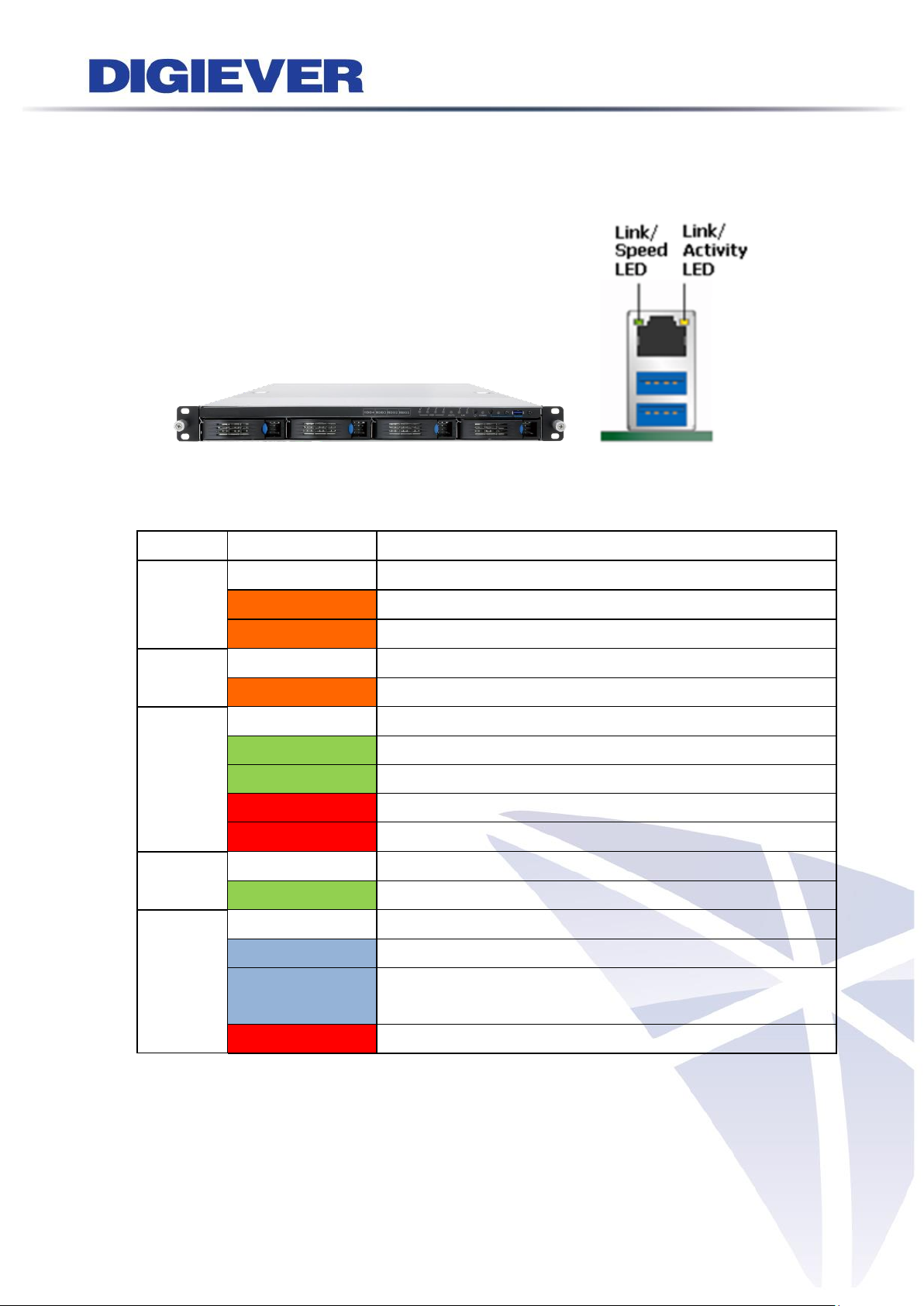
LED on Front Panel
LED
LED Color & Status
Indicate
LAN
Off
LAN Link is not established
Orange
LAN Link is established
Orange blinking
LAN is being accessed
eSATA
Off
No data transmission
Orange blinking
The eSATA device is being accessed
HDD1
HDD2
HDD3
HDD4
Off
Hard disk drive device is not established
Green
Hard disk drive is ready to be accessed
Green blinking
Hard disk drive data is being accessed
Red blinking
Hard disk drive error and need to be checked
Red
Hard disk drive failure and need to be removed
Power
Off
Power Off
Green
Power On
BACKUP
Off
USB device is not detected
Blue
USB device is ready
Blue blinking
NVR data is being copied to the USB device
(Blinking with 1Hz)
Red
Backup error occurs
1.2.19 DS-4300-RMP Pro+ Series
DS-4332-RMP Pro+/ DS-4336-RMP Pro+/ DS-4342-RMP Pro+/ DS-4349-RMP Pro+/
DS-4356-RMP Pro+/ DS-4364-RMP Pro+
Figure 2-19. Front View of DS-4300-RMP Pro+ Series & RJ-45 Port
63
Page 71

LED on RJ-45 Connection at Rear Panel
LED
LED Position
LED/State
Indicate
LAN1
LAN2
Link/Activity
(Right LED)
Off
LAN Link is not established
Yellow
LAN Link is established
Yellow Blinking
LAN activity is occurring
LAN1
LAN2
Speed
(Left LED)
Off
10Mbps connection or no connection
Green
100Mbps connection
Orange
1000Mbps connection
*USB BACKUP will start and beep after 3 seconds user presses BACKUP button.
**To turn off NVR, user needs to press power button at least 2 seconds.
*** The LED in the HDD trays are reserved.
Note: Once users press reset button, configuration of Camera Setting, Recording
Settings, Event & Action Setting, E-Mail Settings, and Server Settings will reset to
default. It is advised to backup system configurations. For more information, refer to
detail information in user manual 5.6.3 Save/Load Configuration.
64
Page 72

LED on Front Panel
LED
LED Color & Status
Indicate
LAN
Off
LAN Link is not established
Orange
LAN Link is established
Orange blinking
LAN is being accessed
eSATA
Off
No data transmission
Orange blinking
The eSATA device is being accessed
HDD1
HDD2
HDD3
HDD4
HDD5
HDD6
HDD7
HDD8
Off
Hard disk drive device is not established
Green
Hard disk drive is ready to be accessed
Green blinking
Hard disk drive data is being accessed
Red blinking
Hard disk drive error and need to be checked
Red
Hard disk drive failure and need to be removed
Power
Off
Power Off
Green
Power On
BACKUP
Off
USB device is not detected
Blue
USB device is ready
Blue blinking
NVR data is being copied to the USB device
(Blinking with 1Hz)
Red
Backup error occurs
1.2.20 DS-8300-RM Pro+ Series
DS-8342-RM Pro+/ DS-8349-RM Pro+/ DS-8356-RM Pro+/ DS-8364-RM Pro+
Figure 2-20. Front View of DS-8300-RM Pro+ Series & RJ-45 Port
65
Page 73

LED on RJ-45 Connection at Rear Panel
LED
LED Position
LED/State
Indicate
LAN1
LAN2
Link/Activity
(Right LED)
Off
LAN Link is not established
Yellow
LAN Link is established
Yellow Blinking
LAN activity is occurring
LAN1
LAN2
Speed
(Left LED)
Off
10Mbps connection or no connection
Green
100Mbps connection
Orange
1000Mbps connection
*USB BACKUP will start and beep after 3 seconds user presses BACKUP button.
**To turn off NVR, user needs to press power button at least 2 seconds.
*** The LED in the HDD trays are reserved.
Note: Once users press reset button, configuration of Camera Setting, Recording
Settings, Event & Action Setting, E-Mail Settings, and Server Settings will reset to
default. It is advised to backup system configurations. For more information, refer to
detail information in user manual 5.6.3 Save/Load Configuration.
66
Page 74

LED on Front Panel
LED
LED Color & Status
Indicate
LAN
Off
LAN Link is not established
Orange
LAN Link is established
Orange blinking
LAN is being accessed
eSATA
Off
No data transmission
Orange blinking
The eSATA device is being accessed
HDD1
HDD2
HDD3
HDD4
HDD5
HDD6
HDD7
HDD8
Off
Hard disk drive device is not established
Green
Hard disk drive is ready to be accessed
Green blinking
Hard disk drive data is being accessed
Red blinking
Hard disk drive error and need to be checked
Red
Hard disk drive failure and need to be removed
Power
Off
Power Off
Green
Power On
BACKUP
Off
USB device is not detected
Blue
USB device is ready
Blue blinking
NVR data is being copied to the USB device
(Blinking with 1Hz)
Red
Backup error occurs
1.2.21 DS-8300-RMP Pro+ Series
DS-8342-RMP Pro+/ DS-8349-RMP Pro+/ DS-8356-RMP Pro+/ DS-8364-RMP Pro+
Figure 2-21. Front View of DS-8300-RMP Pro+ Series & RJ-45 Port
67
Page 75

LED on RJ-45 Connection at Rear Panel
LED
LED Position
LED/State
Indicate
LAN1
LAN2
Link/Activity
(Right LED)
Off
LAN Link is not established
Yellow
LAN Link is established
Yellow Blinking
LAN activity is occurring
LAN1
LAN2
Speed
(Left LED)
Off
10Mbps connection or no connection
Green
100Mbps connection
Orange
1000Mbps connection
*USB BACKUP will start and beep after 3 seconds user presses BACKUP button.
**To turn off NVR, user needs to press power button at least 2 seconds.
*** The LED in the HDD trays are reserved.
Note: Once users press reset button, configuration of Camera Setting, Recording
Settings, Event & Action Setting, E-Mail Settings, and Server Settings will reset to
default. It is advised to backup system configurations. For more information, refer to
detail information in user manual 5.6.3 Save/Load Configuration.
68
Page 76

LED on Front Panel
LED
LED Color & Status
Indicate
LAN
Off
LAN Link is not established
Orange
LAN Link is established
Orange blinking
LAN is being accessed
eSATA
Off
No data transmission
Orange blinking
The eSATA device is being accessed
HDD1
HDD2
HDD3
HDD4
HDD5
HDD6
HDD7
HDD8
Off
Hard disk drive device is not established
Green
Hard disk drive is ready to be accessed
Green blinking
Hard disk drive data is being accessed
Red blinking
Hard disk drive error and need to be checked
Red
Hard disk drive failure and need to be removed
Power
Off
Power Off
Green
Power On
BACKUP
Off
USB device is not detected
Blue
USB device is ready
Blue blinking
NVR data is being copied to the USB device
(Blinking with 1Hz)
Red
Backup error occurs
1.2.22 DS-8400-RM Pro+ Series
DS-8442-RM Pro+/ DS-8449-RM Pro+/ DS-8456-RM Pro+/ DS-8464-RM Pro+
Figure 2-22. Front View of DS-8400-RM Pro+ Series & RJ-45 Port
69
Page 77
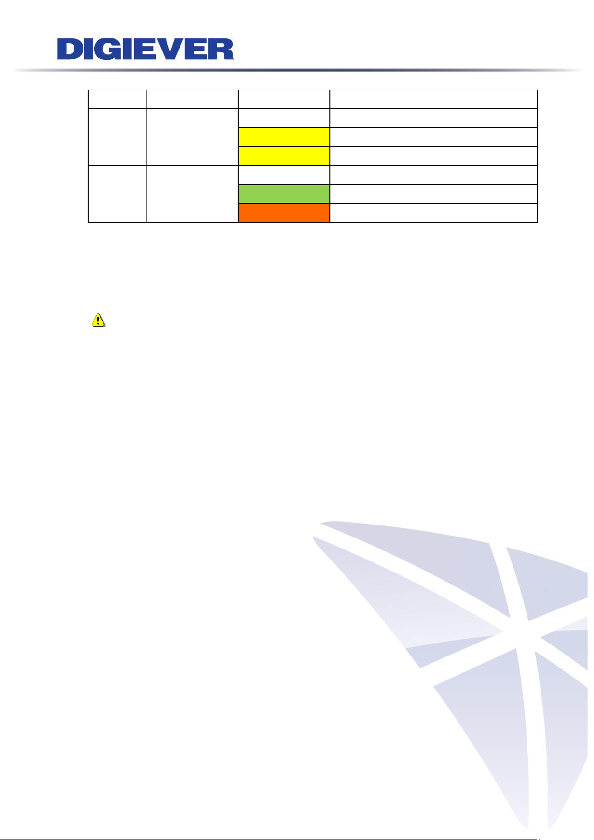
LED on RJ-45 Connection at Rear Panel
LED
LED Position
LED/State
Indicate
LAN1
LAN2
Link/Activity
(Right LED)
Off
LAN Link is not established
Yellow
LAN Link is established
Yellow Blinking
LAN activity is occurring
LAN1
LAN2
Speed
(Left LED)
Off
10Mbps connection or no connection
Green
100Mbps connection
Orange
1000Mbps connection
*USB BACKUP will start and beep after 3 seconds user presses BACKUP button.
**To turn off NVR, user needs to press power button at least 2 seconds.
*** The LED in the HDD trays are reserved.
Note: Once users press reset button, configuration of Camera Setting, Recording
Settings, Event & Action Setting, E-Mail Settings, and Server Settings will reset to
default. It is advised to backup system configurations. For more information, refer to
detail information in user manual 5.6.3 Save/Load Configuration.
70
Page 78
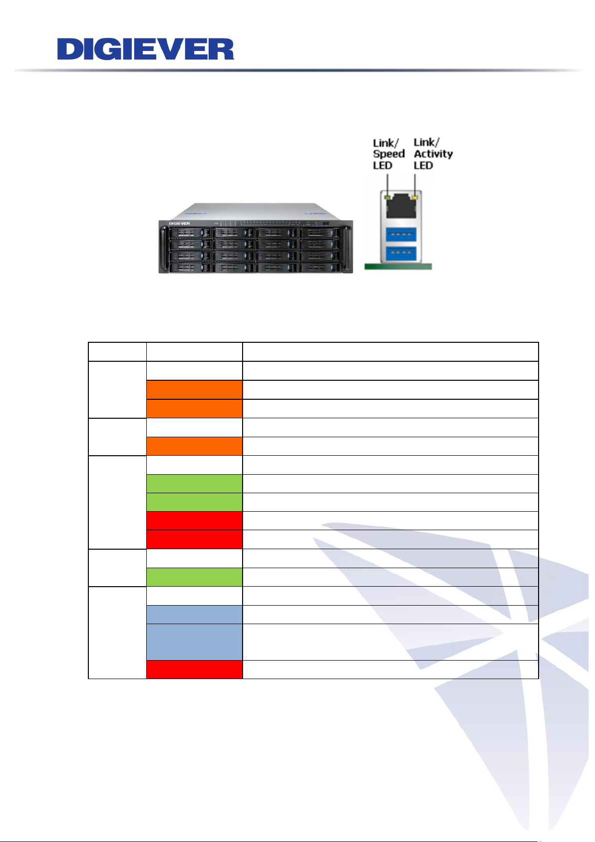
LED on Front Panel
LED
LED Color & Status
Indicate
LAN1
LAN2
Off
LAN Link is not established
Orange
LAN Link is established
Orange blinking
LAN is being accessed
eSATA
Off
No data transmission
Orange blinking
The eSATA device is being accessed
HDD1
to
HDD16
Off
Hard disk drive device is not established
Green
Hard disk drive is ready to be accessed
Green blinking
Hard disk drive data is being accessed
Red blinking
Hard disk drive error and need to be checked
Red
Hard disk drive failure and need to be removed
Power
Off
Power Off
Green
Power On
BACKUP
Off
USB device is not detected
Blue
USB device is ready
Blue blinking
NVR data is being copied to the USB device
(Blinking with 1Hz)
Red
Backup error occurs
1.2.23 DS-16200-RM Pro+ Series
DS-16216-RM Pro+/ DS-16220-RM Pro+/ DS-16225-RM Pro+/ DS-16232-RM Pro+/
DS-16236-RM Pro+
Figure 2-23. Front View of DS-16200-RM Pro+ Series & RJ-45 Port
71
Page 79

LED on RJ-45 Connection at Rear Panel
LED
LED Position
LED/State
Indicate
LAN1
LAN2
Link/Activity
(Right LED)
Off
LAN Link is not established
Yellow
LAN Link is established
Yellow Blinking
LAN activity is occurring
LAN1
LAN2
Speed
(Left LED)
Off
10Mbps connection or no connection
Green
100Mbps connection
Orange
1000Mbps connection
*USB BACKUP will start and beep after 3 seconds user presses BACKUP button.
**To turn off NVR, user needs to press power button at least 2 seconds.
*** The LED in the HDD trays are reserved.
Note: Once users press reset button, configuration of Camera Setting, Recording
Settings, Event & Action Setting, E-Mail Settings, and Server Settings will reset to
default. It is advised to backup system configurations. For more information, refer to
detail information in user manual 5.6.3 Save/Load Configuration.
72
Page 80

LED on Front Panel
LED
LED Color & Status
Indicate
LAN
Off
LAN Link is not established
Orange
LAN Link is established
Orange blinking
LAN is being accessed
eSATA
Off
No data transmission
Orange blinking
The eSATA device is being accessed
HDD1
to
HDD16
Off
Hard disk drive device is not established
Green
Hard disk drive is ready to be accessed
Green blinking
Hard disk drive data is being accessed
Red blinking
Hard disk drive error and need to be checked
Red
Hard disk drive failure and need to be removed
Power
Off
Power Off
Green
Power On
BACKUP
Off
USB device is not detected
Blue
USB device is ready
Blue blinking
NVR data is being copied to the USB device
(Blinking with 1Hz)
Red
Backup error occurs
1.2.24 DS-16300-RM Pro+ Series
DS-16316-RM Pro+/ DS-16320-RM Pro+/ DS-16325-RM Pro+/ DS-16332-RM Pro+/
DS-16336-RM Pro+/ DS-16342-RM Pro+/ DS-16349-RM Pro+/ DS-16356-RM Pro+/
DS-16364-RM Pro+
Figure 2-24. Front View of DS-16300-RM Pro+ Series & RJ-45 Port
73
Page 81

LED on RJ-45 Connection at Rear Panel
LED
LED Position
LED/State
Indicate
LAN1
LAN2
Link/Activity
(Right LED)
Off
LAN Link is not established
Yellow
LAN Link is established
Yellow Blinking
LAN activity is occurring
LAN1
LAN2
Speed
(Left LED)
Off
10Mbps connection or no connection
Green
100Mbps connection
Orange
1000Mbps connection
*USB BACKUP will start and beep after 3 seconds user presses BACKUP button.
**To turn off NVR, user needs to press power button at least 2 seconds.
*** The LED in the HDD trays are reserved.
Note: Once users press reset button, configuration of Camera Setting, Recording
Settings, Event & Action Setting, E-Mail Settings, and Server Settings will reset to
default. It is advised to backup system configurations. For more information, refer to
detail information in user manual 5.6.3 Save/Load Configuration.
74
Page 82

LED on Front Panel
LED
LED Color & Status
Indicate
LAN
Off
LAN Link is not established
Orange
LAN Link is established
Orange blinking
LAN is being accessed
eSATA
Off
No data transmission
Orange blinking
The eSATA device is being accessed
HDD1
to
HDD16
Off
Hard disk drive device is not established
Green
Hard disk drive is ready to be accessed
Green blinking
Hard disk drive data is being accessed
Red blinking
Hard disk drive error and need to be checked
Red
Hard disk drive failure and need to be removed
Power
Off
Power Off
Green
Power On
BACKUP
Off
USB device is not detected
Blue
USB device is ready
Blue blinking
NVR data is being copied to the USB device
(Blinking with 1Hz)
Red
Backup error occurs
1.2.25 DS-16400-RM Pro+ Series
DS-16442-RM Pro+/ DS-16449-RM Pro+/ DS-16456-RM Pro+/ DS-16464-RM Pro+
Figure 2-25. Front View of DS-16400-RM Pro+ Series & RJ-45 Port
75
Page 83

LED on RJ-45 Connection at Rear Panel
LED
LED Position
LED/State
Indicate
LAN1
LAN2
Link/Activity
(Right LED)
Off
LAN Link is not established
Yellow
LAN Link is established
Yellow Blinking
LAN activity is occurring
LAN1
LAN2
Speed
(Left LED)
Off
10Mbps connection or no connection
Green
100Mbps connection
Orange
1000Mbps connection
*USB BACKUP will start and beep after 3 seconds user presses BACKUP button.
**To turn off NVR, user needs to press power button at least 2 seconds.
*** The LED in the HDD trays are reserved.
Note: Once users press reset button, configuration of Camera Setting, Recording
Settings, Event & Action Setting, E-Mail Settings, and Server Settings will reset to
default. It is advised to backup system configurations. For more information, refer to
detail information in user manual 5.6.3 Save/Load Configuration.
76
Page 84

LED on Front Panel
LED
LED Color & Status
Indicate
LAN
Off
LAN Link is not established
Orange
LAN Link is established
Orange blinking
LAN is being accessed
eSATA
Off
No data transmission
Orange blinking
The eSATA device is being accessed
HDD1
to
HDD16
Off
Hard disk drive device is not established
Green
Hard disk drive is ready to be accessed
Green blinking
Hard disk drive data is being accessed
Red blinking
Hard disk drive error and need to be checked
Red
Hard disk drive failure and need to be removed
Power
Off
Power Off
Green
Power On
BACKUP
Off
USB device is not detected
Blue
USB device is ready
Blue blinking
NVR data is being copied to the USB device
(Blinking with 1Hz)
Red
Backup error occurs
1.2.26 DS-16500-RM Pro+ Series
DS-16542-RM Pro+/ DS-16549-RM Pro+/ DS-16556-RM Pro+/ DS-16564-RM Pro+
Figure 2-25. Front View of DS-16500-RM Pro+ Series & RJ-45 Port
77
Page 85

LED on RJ-45 Connection at Rear Panel
LED
LED Position
LED/State
Indicate
LAN1
LAN2
Link/Activity
(Right LED)
Off
LAN Link is not established
Yellow
LAN Link is established
Yellow Blinking
LAN activity is occurring
LAN1
LAN2
Speed
(Left LED)
Off
10Mbps connection or no connection
Green
100Mbps connection
Orange
1000Mbps connection
*USB BACKUP will start and beep after 3 seconds user presses BACKUP button.
**To turn off NVR, user needs to press power button at least 2 seconds.
*** The LED in the HDD trays are reserved.
Note: Once users press reset button, configuration of Camera Setting, Recording
Settings, Event & Action Setting, E-Mail Settings, and Server Settings will reset to
default. It is advised to backup system configurations. For more information, refer to
detail information in user manual 5.6.3 Save/Load Configuration.
78
Page 86

LED on Front Panel
LED
LED Color & Status
Indicate
LAN
Off
LAN Link is not established
Orange
LAN Link is established
Orange blinking
LAN is being accessed
HDD
Off
Hard disk drive device is not established
Green
Hard disk drive is ready to be accessed
Green blinking
Hard disk drive data is being accessed
Red blinking
Hard disk drive error and need to be checked
Red
Hard disk drive failure and need to be removed
Power
Off
Power Off
Green
Power On
3G
Off
3G module is not ready to be accessed
Green
3G module is ready to be accessed
Wi-Fi
Off
Wi-Fi module is not ready to be accessed
Green
Wi-Fi module is ready to be accessed
POE
Off
POE module is not ready to be accessed
Green
POE module is ready to be accessed
GPS
Off
GPS module is not ready to be accessed
Green
GPS module is ready to be accessed
LED on RJ-45 Connection at Rear Panel
LED
LED Position
LED/State
Indicate
LAN1
LAN2
LAN3
LAN4
Link/Activity
(Right LED)
Off
LAN Link is not established
Yellow
LAN Link is established
Yellow Blinking
LAN activity is occurring
1.2.27 MN-1100 Pro+ Series
MN-1105 Pro+/ MN-1109 Pro+/ MN-1112 Pro+/MN-1116 Pro+ /MN-1120 Pro+/
MN-1125 Pro+/ MN-1132 Pro+/ MN-1136 Pro+
Figure 2-27. Front View of MN-1100 Pro+ Series & RJ-45 Port
79
Page 87
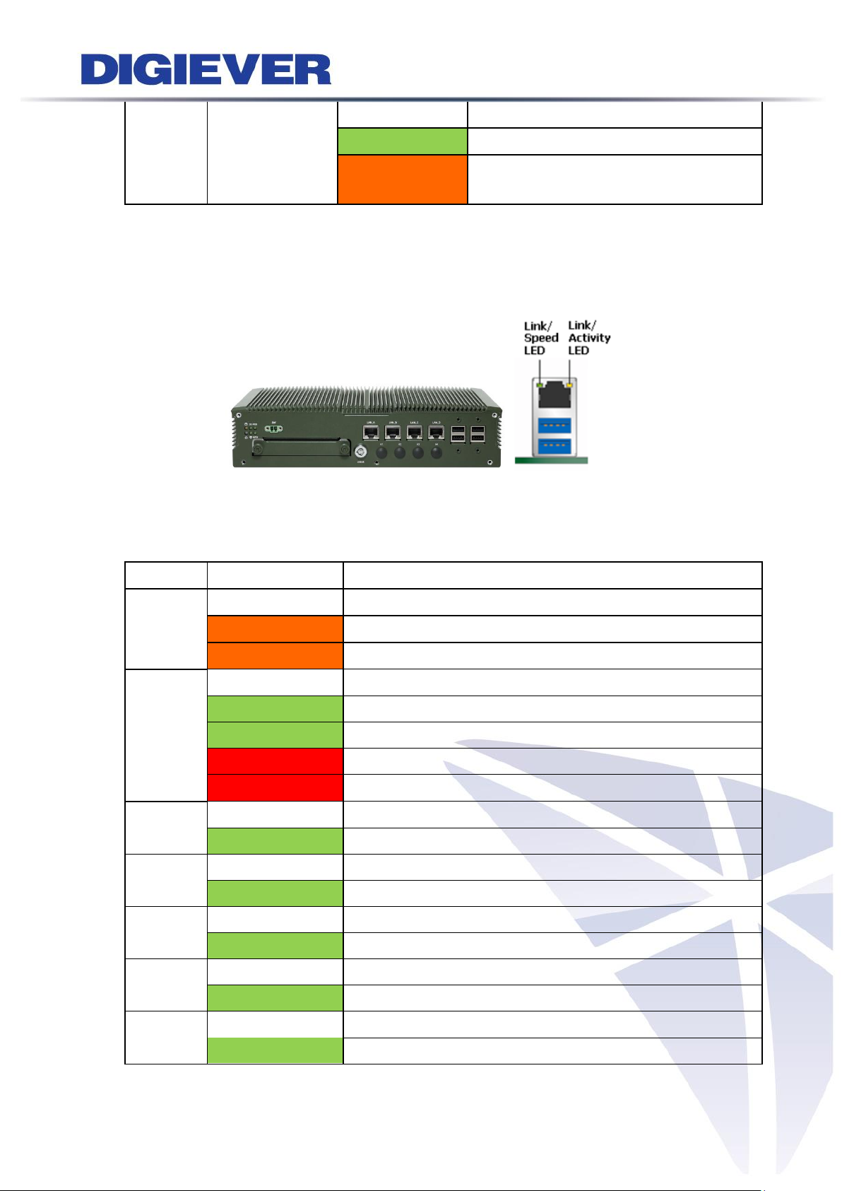
LAN1
LAN2
LAN3
LAN4
Speed
(Left LED)
Off
10Mbps connection or no connection
Green
100Mbps connection
Orange
1000Mbps connection
LED on Front Panel
LED
LED Color & Status
Indicate
LAN
Off
LAN Link is not established
Orange
LAN Link is established
Orange blinking
LAN is being accessed
HDD
Off
Hard disk drive device is not established
Green
Hard disk drive is ready to be accessed
Green blinking
Hard disk drive data is being accessed
Red blinking
Hard disk drive error and need to be checked
Red
Hard disk drive failure and need to be removed
Power
Off
Power Off
Green
Power On
3G
Off
3G module is not ready to be accessed
Green
3G module is ready to be accessed
Wi-Fi
Off
Wi-Fi module is not ready to be accessed
Green
Wi-Fi module is ready to be accessed
POE
Off
POE module is not ready to be accessed
Green
POE module is ready to be accessed
GPS
Off
GPS module is not ready to be accessed
Green
GPS module is ready to be accessed
1.2.28 MN-2100 Pro+ Series
MN-2105 Pro+/ MN-2109 Pro+/ MN-2112 Pro+/MN-2116 Pro+ /MN-2120 Pro+/
MN-2125 Pro+/ MN-2132 Pro+/ MN-2136 Pro+
Figure 2-28. Front View of MN-2100 Pro+ Series & RJ-45 Port
80
Page 88

LED on RJ-45 Connection at Rear Panel
LED
LED Position
LED/State
Indicate
LAN1
LAN2
LAN3
LAN4
Link/Activity
(Right LED)
Off
LAN Link is not established
Yellow
LAN Link is established
Yellow Blinking
LAN activity is occurring
LAN1
LAN2
LAN3
LAN4
Speed
(Left LED)
Off
10Mbps connection or no connection
Green
100Mbps connection
Orange
1000Mbps connection
81
Page 89

1.3 Dual/Mirror Display Solution: HDMI/VGA/DVI-I Connection
DS-4200 Pro, DS-4200-RM Pro, DS-4200-RMP Pro, DS-8200-RM Pro, DS-8200-RMP
Pro, DS-4200 Pro+, DS-4200-RM Pro+, DS-4200-RMP Pro+, DS-8200-RM Pro+,
DS-8200-RMP Pro+, DS-4300 Pro+, DS-4300-RM Pro+, DS-4300-RMP Pro+,
DS-8300-RM Pro+, DS-8300-RMP Pro+, DS-8400-RM Pro+, DS-16200-RM Pro+ and
DS-16300-RM Pro+, MN-1100 Pro+, MN-2100 Pro+ series provide HDMI and VGA
port for local display. Users can connect both of HDMI and VGA at the same time for
video output.
DS-1100 Pro Series, DS-2100 Pro Series, DS-1100 Pro+ and DS-2100 Pro+ Series
provide HDMI and DVI-I port for local display. Users can connect both of HDMI and
DVI-I at the same time for video output.
Mirror display scenario
Scenario A: If both monitors are Full HD (1920x1080), those will be shown as Full HD.
Scenario B: If both monitors are VGA (1024x768), those will be shown all as VGA.
Scenario C: If one of monitors is 1920x1080 and another is 1024x768, both monitors
are set as 1024x768
Dual display scenario
Scenario: If both monitors are Full HD (1920x1080), those will be shown as Full HD.
1024 X 768 resolutions is not supported in dual display.
Dual display is ONLY supported in NVR Plus series.
82
Page 90

Chapter 2. NVR Installation
2.1 Remote Web Browser PC System Requirements
The following information is the minimum required specification for remote
Windows PC, which users can open a remote browser from the PC to access the
Linux NVR server on the network.
Operating System
Microsoft® Windows® Vista /7 / 8 (32-bit and 64-bit)
Browsers in Windows OS (32-bit)
Microsoft® Internet Explorer 8.0 or above, Firefox 25 or above, Opera 17.0 or
above, Safari 5.1.7 or above
CPU
For channels under 16 : Intel® Dual core CPU 3.0 GHz or above.
For channels over 16 : Intel® i5/i7 CPU 3.3 GHz or above.
Network
Minimum 10/100 Ethernet (Gigabit Ethernet is recommended)
Note: * User is suggested to connect cameras and NVR with Gigabit switch.
Memory
For channels under 16: DDR3 4G or above.
For channels over 16: DDR3 8G or above
Graphics Adapter
AGP or PCI-Express, minimum 1024×768, 16 bit colors, 1G memory or above
Note: It is highly recommended to use a graphics adaptor which provides
higher than resolutions 1024 x 768 in order to experience the full benefits
of the software.
Make sure the display DPI setting is set to default at 96DPI
To set DPI value, right-click on desktop, choose “Settings” tab >>
“Advanced” >> “General.”
CD-ROM Drive
It is necessary to read the operating instructions in the provided CD-ROM.
Adobe Reader
It is necessary to read the operating instructions in the provided CD-ROM. The
audio function will not work if a sound card is not installed in the PC.
Note: Audio may be interrupted depending on network traffic.
83
Page 91

2.2 Connect to NVR
To begin, please insert the product CD-ROM in a PC to access the Quick Guide, User
Manual and install the utilities. As user runs the product CD, the following menu is
displayed.
2.2.1 Quick Guide
Click “Quick Guide” to enter the folder and double click the file to
open. Please read Quick Guide to quickly understand the process of NVR installation.
2.2.2 Install NVR Search
Click “Install EZ Search” to find NVR in the network. Please follow
the instructions to install and EZ Search will run automatically.
84
Page 92
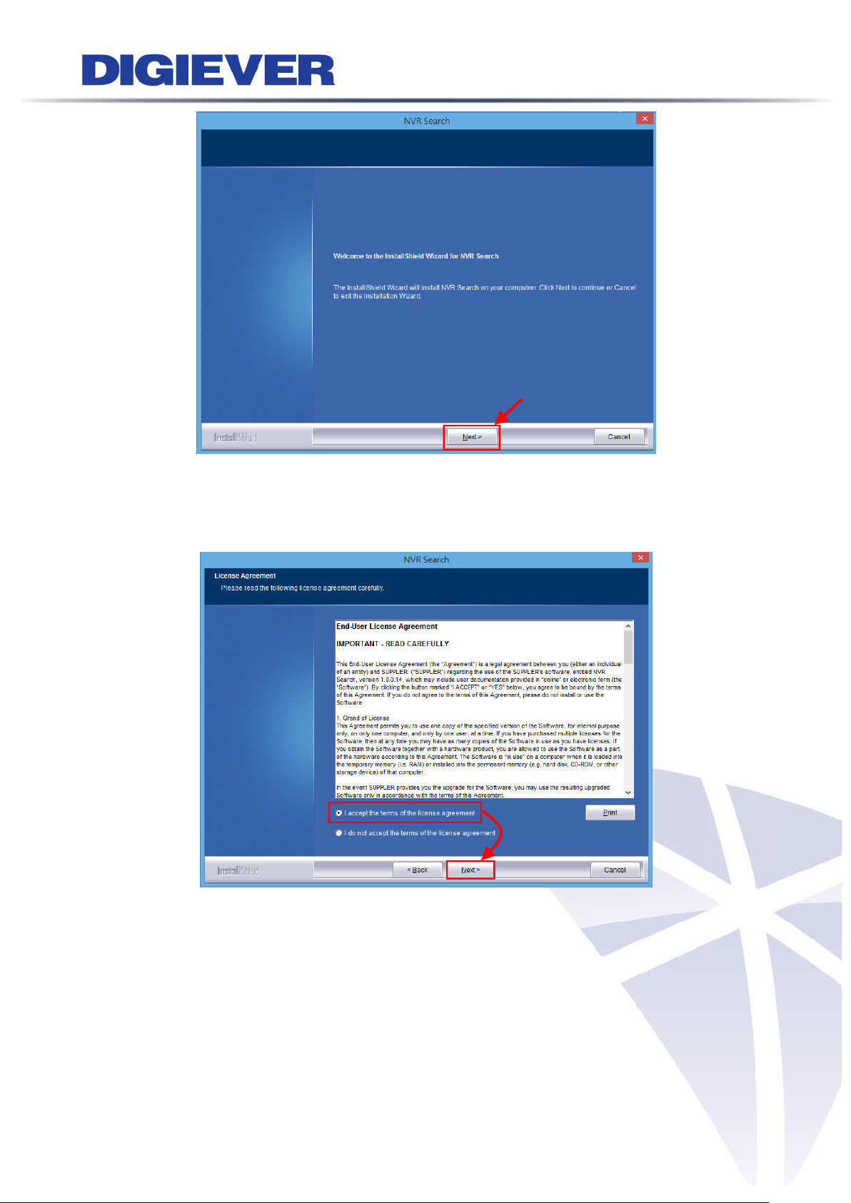
When installing NVR Search, Shield Wizard window for NVR Search will pop up.
Click “Next” to continue installation.
Read the license agreement and click “I accept the terms of the license agreement”.
Click “Next” to continue installation.
85
Page 93

Select a location of destination and select a folder where the setup can install files.
The default location is: C:\Program Files (x86)\NVR\NVR Search. Users can also
install NVR Search in other folder by clicking “Change” and select a location as below.
Click “OK” to save the setting.
Once a folder is selected, please click “OK” to continue installation.
86
Page 94

The window shows that the InstallShield Wizard is installing NVR Search.
Please wait until the Wizard completes the installation.
The InstallShield has successfully installed NVR Search. Select “Create Desktop
Shortcut”/ “Create Quick Launch Shortcut”/ “Create Start Menu Shortcut” and
please click “Next” to continue.
87
Page 95

The installation is complete. Please click “Launch application when done installing”
to execute NVR Search.
After finishing the setup, the window of NVR Search will pop up.
NVR Search will execute automatically and show NO., Name, IP Address, Mac
Address and Model name of connected NVR.
Users can click “Search” to search NVR.
You can click “Connect” or double click on one NVR; IE browser will pop up
automatically
88
Page 96

Introduction of NVR Search
NVR Search provides three kinds of toolbars for users:
1. File
You can click “Exit” to leave NVR Search and close the window.
2. Setting
Configure UPnP and Network by clicking “Setting” in the top left or in the middle
right.
89
Page 97

Note: Users will be prompted to enter the login information of NVR before
being allowed to change the setting.
When accessing the NVR setting, users will be prompted to enter username and
password. For the first-time use, the default username and password are
admin/admin. When the correct username and password have been entered, click
“Login” to continue.
1) UPnP
Universal Plug and Play (UPnP) simplifies the process of adding a NVR to a local
area network. Once connected to a LAN, NVR will automatically appear on the
internet. You can rename UPnP Name on the NVR. Click “OK” to finish the
setting.
90
Page 98

2) Network
NVR provides two network settings: DHCP and Static IP.
91
Page 99

3. Option
Option provides users to change language.
92
Page 100

2.2.3 Install NVR Decoder
Click “Install S-NVR Decoder” to install decoder and follow
the instructions to setup.
Install Shield Wizard window will pop up and please click “Next” to continue
installation.
Read license agreement and click “I accept the terms of the license agreement.”
Click “Next” to continue installation.
93
 Loading...