

Page 1

Network Video Recorder
User Manual
1.0.0.21
Information in this document is subject to change without notice.
© Copyright 2015. All rights reserved.
Page 2

i
Table of Contents
Chapter 1. Introduction .............................................................................. 1
1.1 Hardware Description................................................................................... 2
1.1.1 DS-2000 Series ................................................................................... 2
1.1.2 DS-4000 Series ................................................................................... 3
1.1.3 DS-1100 Pro Series ............................................................................ 4
1.1.4 DS-2100 Pro Series ............................................................................ 5
1.1.5 DS-4200 Pro Series ............................................................................ 6
1.1.6 DS-4200-RM Pro Series ..................................................................... 7
1.1.7 DS-8200-RM Pro Series ..................................................................... 8
1.1.8 DS-1100 Pro+ Series.......................................................................... 9
1.1.9 DS-2100 Pro+ Series........................................................................ 10
1.1.10 DS-4200 Pro+ Series........................................................................ 11
1.1.11 DS-4200-RM Pro+ Series ................................................................. 12
1.1.12 DS-8200-RM Pro+ Series ................................................................. 13
1.1.13 DS-4300 Pro+ Series........................................................................ 14
1.1.14 DS-4300-RM Pro+ Series ................................................................. 15
1.1.15 DS-8300-RM Pro+ Series ................................................................. 16
1.2 LED Indicators Status ................................................................................... 17
1.2.1 DS-2000 Series ................................................................................. 17
1.2.2 DS-4000 Series ................................................................................. 19
1.2.3 DS-1100 Pro Series .......................................................................... 21
1.2.4 DS-2100 Pro Series .......................................................................... 22
1.2.5 DS-4200 Pro Series .......................................................................... 23
1.2.6 DS-4200-RM Pro Series ................................................................... 25
1.2.7 DS-8200-RM Pro Series ................................................................... 27
1.2.8 DS-1100 Pro+ Series........................................................................ 29
1.2.9 DS-2100 Pro+ Series........................................................................ 30
1.2.10 DS-4200 Pro+ Series........................................................................ 31
1.2.11 DS-4200-RM Pro+ Series ................................................................. 33
Page 3

ii
1.2.12 DS-8200-RM Pro+ Series ................................................................. 35
1.2.13 DS-4300 Pro+ Series........................................................................ 37
1.2.14 DS-4300-RM Pro+ Series ................................................................. 39
1.2.15 DS-8300-RM Pro+ Series ................................................................. 41
1.3 Dual Display Solution: HDMI/VGA/DVI-I Connection ........................... 43
Chapter 2. NVR Installation ...................................................................... 44
2.1 Remote Web Browser PC System Requirements .................................... 44
2.2 Connect to NVR ........................................................................................... 45
2.2.1 Quick Guide ..................................................................................... 45
2.2.2 Install EZ Search .............................................................................. 45
2.2.3 Install NVR Decoder ........................................................................ 54
2.2.4 Install NVRPlayer ............................................................................. 56
2.2.5 Install NVR Check ............................................................................ 62
2.2.6 User Manual ..................................................................................... 66
2.2.7 Browse CD ....................................................................................... 66
2.2.8 Activate Live View Service ............................................................. 67
2.3 Quick Configuration ................................................................................... 70
2.3.1 Start .................................................................................................. 70
2.3.2 Network Settings ............................................................................. 71
2.3.3 Server Settings ................................................................................ 72
2.3.4 Date & Time ...................................................................................... 73
2.3.5 Disk Management ............................................................................ 74
2.3.6 Camera Settings .............................................................................. 82
2.3.7 Finish ................................................................................................ 91
Chapter 3. Use NVR by Local Display ..................................................... 92
3.1 Log in NVR .................................................................................................... 92
3.1.1 Anonymous login ............................................................................ 93
3.1.2 Virtual Keyboard .............................................................................. 94
3.2 Quick Configuration ................................................................................... 95
3.3 Liveview ........................................................................................................ 95
Page 4

iii
3.3.1 Select View Modes on Liveview Page ........................................... 95
3.3.2 Main Functions of Liveview ............................................................ 97
3.3.3 Right Click Functions on Video Window ..................................... 104
3.3.4 Zooming with Mouse Scroll .......................................................... 107
3.3.5 Two-way Audio .............................................................................. 108
3.4 Playback .....................................................................................................108
3.4.1 Steps to Playback Videos ............................................................. 109
3.4.2 Main Functions of Playback ......................................................... 113
3.4.3 Export Files .................................................................................... 115
3.4.4 Snapshot ........................................................................................ 116
3.4.5 Zooming with Mouse Scroll .......................................................... 116
3.5 Others ...........................................................................................................116
3.5.1 Screenshot on Local Display ....................................................... 116
3.5.2 System Upgrade on Local Display ............................................... 117
3.5.3 USB Backup by Hardware or Software USB BACKUP Buttons ..... 117
Chapter 4. Use NVR by Remote Web Browser ..................................... 117
4.1 Liveview .......................................................................................................117
4.1.1 Select View Modes on Liveview Page ......................................... 118
4.1.2 Main Functions for Liveview ........................................................ 119
4.1.3 Right Click Functions on Video Window ..................................... 129
4.1.4 Zooming with Mouse scroll .......................................................... 132
4.1.5 Two-way Audio .............................................................................. 132
4.1.6 Built-in Mini-CMS Server ............................................................... 133
4.2 Multi-layer Dynamic E-Map .....................................................................137
4.2.1 Feature Introduction ...................................................................... 137
4.2.2 Add or Delete Multi-layer E-Maps ................................................ 139
4.2.3 Deploy Cameras ............................................................................ 140
4.2.4 Enable/ Disable Automatically Pop-up Event Window .............. 142
4.2.5 Event Log History .......................................................................... 143
4.3 Playback .....................................................................................................144
Page 5

iv
4.3.1 Steps to Playback Videos ............................................................. 144
4.3.2 Smart Search ................................................................................. 149
4.3.3 Main Functions on Playback ........................................................ 151
4.3.4 Zooming with Mouse scroll .......................................................... 156
4.3.5 Export ............................................................................................. 158
4.4 Play Video Files ..........................................................................................163
4.4.1 Windows Networking .................................................................... 163
4.4.2 FTP Service .................................................................................... 168
4.4.3 Naming Rule of Video files ........................................................... 171
Chapter 5. Configuration ........................................................................ 171
5.1 IP Camera ...................................................................................................171
5.1.1 Camera Settings ............................................................................ 171
5.1.2 Camera Parameter ......................................................................... 172
5.1.3 Camera Status ............................................................................... 175
5.2 Recording & Events ....................................................................................176
5.2.1 Recording Settings ........................................................................ 177
5.2.2 Recording Schedule ...................................................................... 179
5.2.3 Event & Action Management ........................................................ 181
5.2.4 Advanced Setting .......................................................................... 187
5.2.5 E-Mail .............................................................................................. 187
5.3 Disk Management .....................................................................................189
5.3.1 Disk Management .......................................................................... 189
5.3.2 File System Management .............................................................. 191
5.3.3 File Sharing Service ...................................................................... 192
5.4 Cloud ............................................................................................................194
5.4.1 Setup Dropbox Service ................................................................. 194
5.4.2 Share Files to Dropbox Server ..................................................... 195
5.4.3 Remove Configuration and Online Sync ..................................... 196
5.5 Network Setup ............................................................................................197
5.5.1 Network Setup ............................................................................... 197
Page 6

v
5.5.2 Network Service ............................................................................. 201
5.5.3 DDNS .............................................................................................. 203
5.6 Management ..............................................................................................204
5.6.1 User Management .......................................................................... 204
5.6.2 Log System .................................................................................... 209
5.6.3 Save/Load Configuration .............................................................. 213
5.6.4 USB Backup ................................................................................... 215
5.6.5 Remote Backup ............................................................................. 221
5.6.6 External IO Device ......................................................................... 223
5.6.7 UPS Management .......................................................................... 224
5.6.8 Failover ........................................................................................... 225
5.7 System ..........................................................................................................228
5.7.1 Device Information ........................................................................ 228
5.7.2 System Upgrade ............................................................................ 229
5.7.3 Language ........................................................................................ 233
5.7.4 Date &Time ..................................................................................... 234
5.7.5 Buzzer ............................................................................................. 236
5.7.6 Reboot &Shutdown ....................................................................... 236
Appendix: Notice and Warning ........................................................................237
Page 7

1
Chapter 1. Introduction
Before You Use This Product
When you first open the product’s package, verify that all the accessories listed on
the “Package Contents” of “Quick Installation Guide” are included. Before installing
the NVR, please read the instructions in the “Quick Installation Guide” to avoid
misuse and then follow the instructions in the “Hard Disk Installation” section to
avoid damages due to faulty assembly or installation.
Page 8
2
1.1 Hardware Description
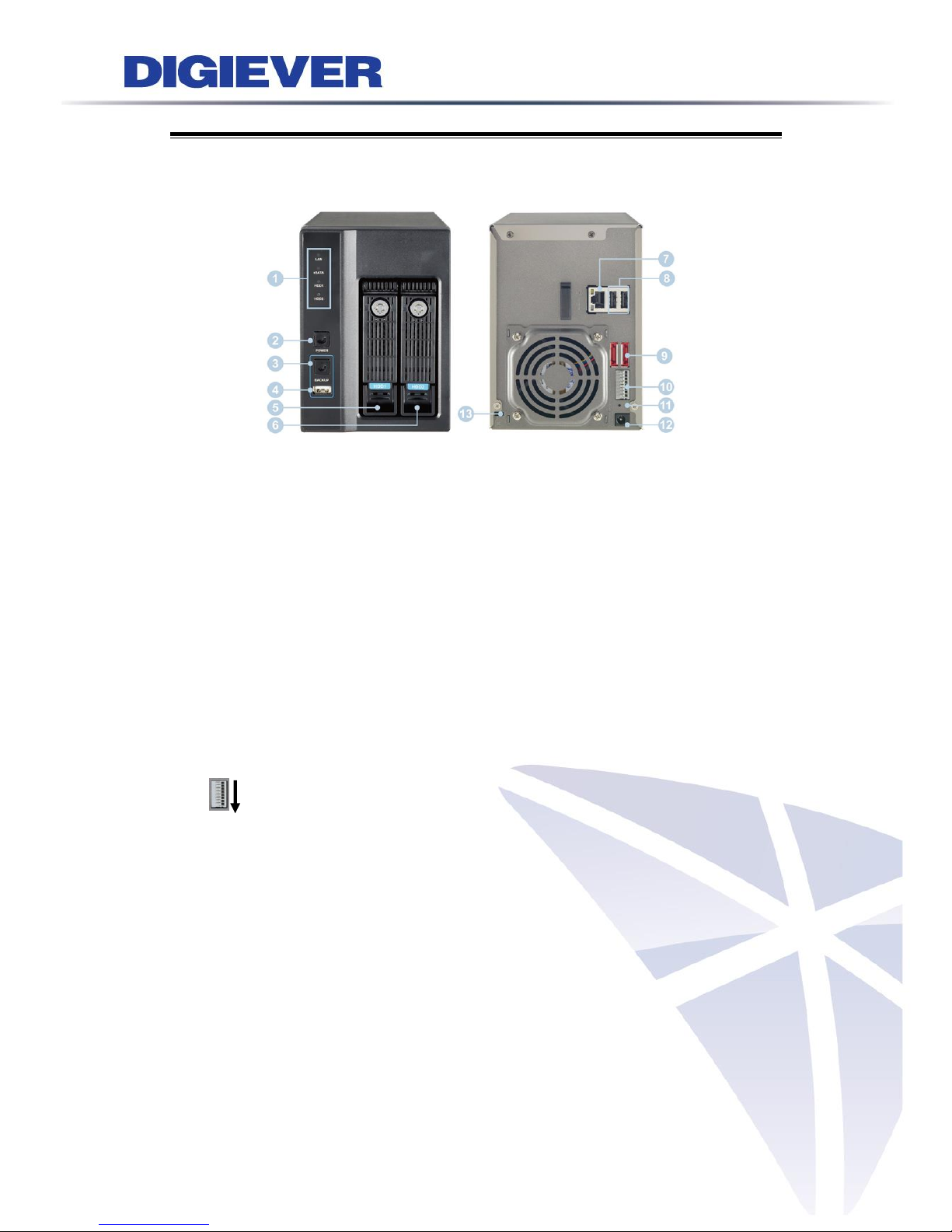
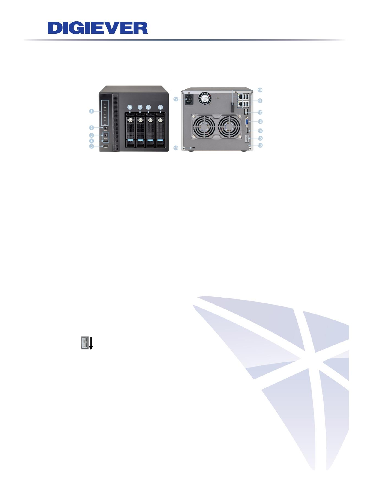
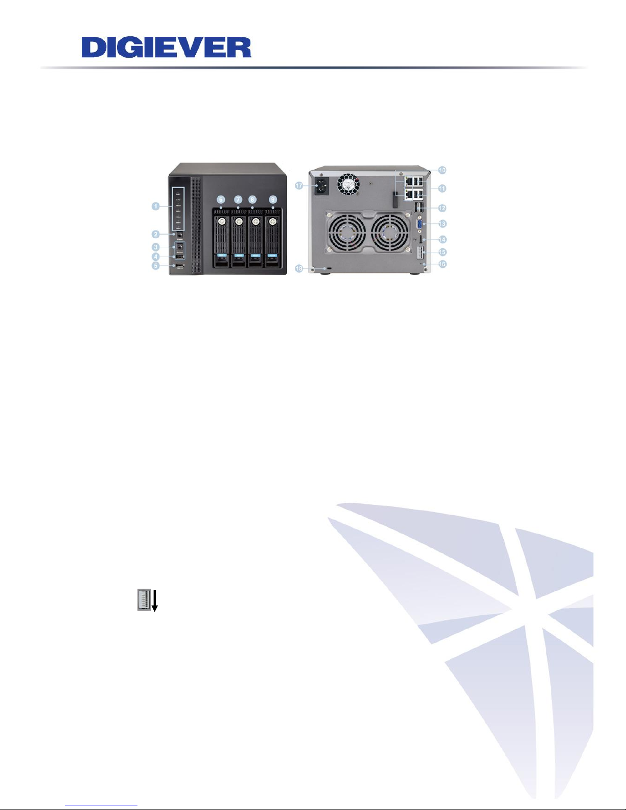
1.1.1 DS-2000 Series
DS-2005/DS-2009/DS-2012/DS-2016/DS-2020/DS-2025/DS-2032
Figure 1-1. Front & Rear View of DS-2000 Series
1. Figure LED indicators: LAN, eSATA, HDD1, HDD2
2. Power button
3. USB BACKUP button- Auto video backup
4. USB 2.0 X1(Support auto video backup)
5. HDD1
6. HDD2
7. Gigabit LAN
8. USB 2.0 x 2
9. eSATA x 2
10. DI/DO (4 in 2 out)
Top to bottom: Vcc5V, GND, DI-1, DI-2, DI-3, DI-4, DO-1, DO-2
11. Reset button*
12. Power connector
13. K-lock security slot
Page 9
3
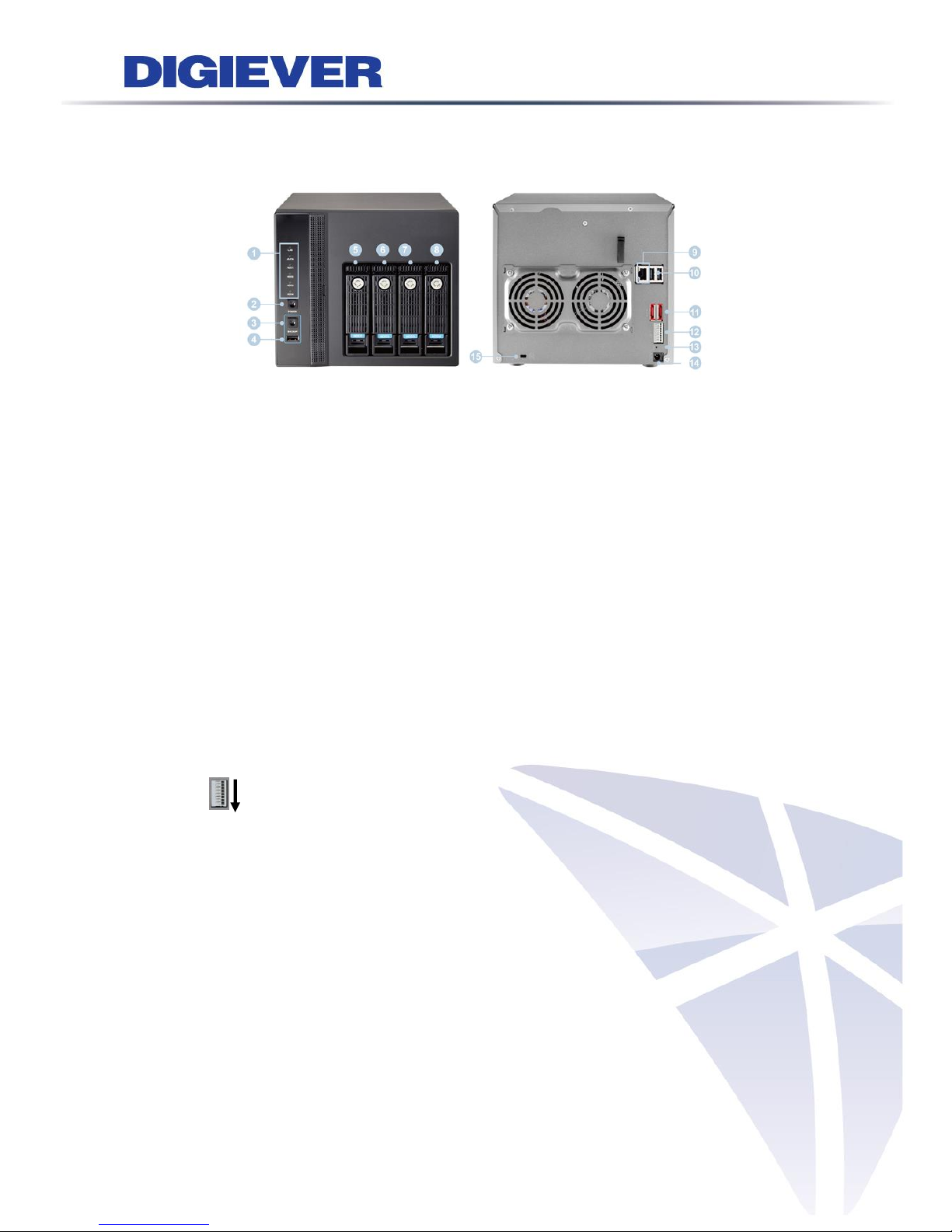
1.1.2 DS-4000 Series
DS-4005/DS-4009/DS-4012/DS-4016/DS-4020/ DS-4025/ DS-4032
Figure 1-2. Front & Rear View of DS-4000 Series
1. LED indicators: LAN, eSATA, HDD1, HDD2, HDD3, HDD4
2. Power button
3. USB BACKUP button- Auto video backup
4. USB 2.0 x 1 (Support auto video backup)
5. HDD1
6. HDD2
7. HDD3
8. HDD4
9. Gigabit LAN
10. USB 2.0 x 2
11. eSATA x 2
12. DI/DO (4 in 2 out)
Top to bottom: Vcc5V, GND, DI-1, DI-2, DI-3, DI-4, DO-1, DO-2
13. Reset button*
14. Power connector
15. K-lock security slot
Page 10
4
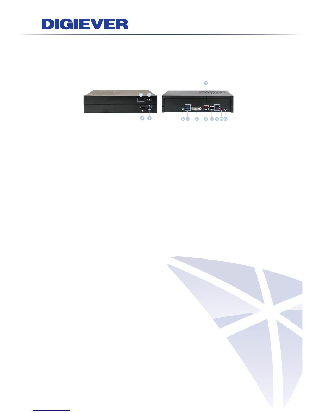
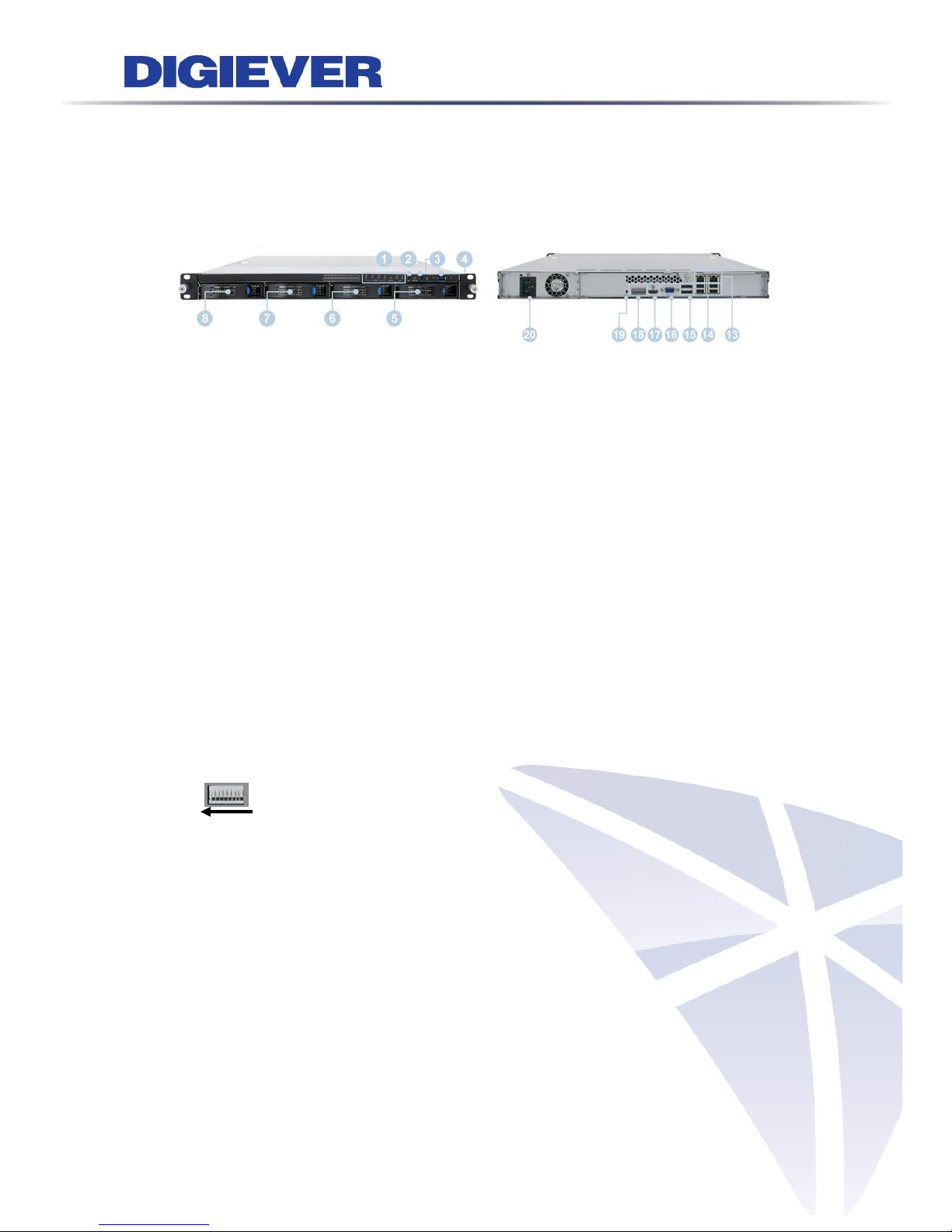
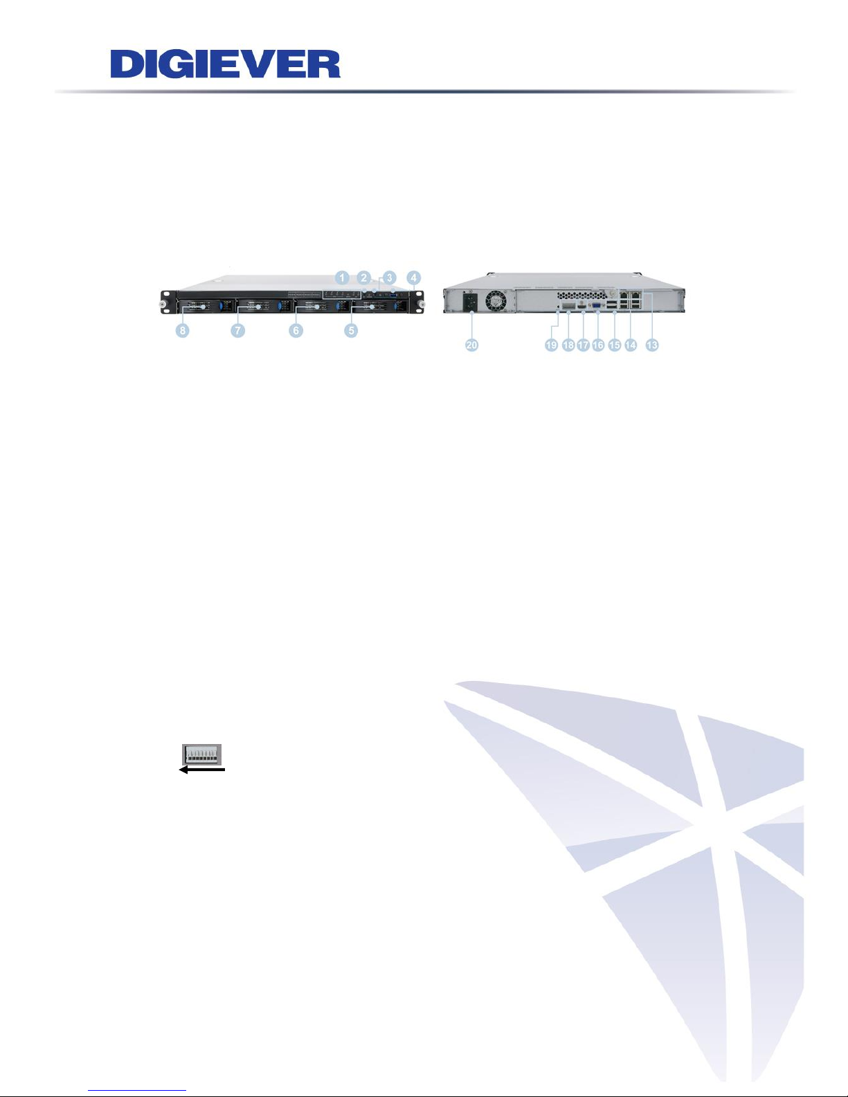
1.1.3 DS-1100 Pro Series
DS-1105 Pro/ DS-1109 Pro/ DS-1112 Pro/ DS-1116 Pro/ DS-1120 Pro/ DS-1125 Pro/
DS-1132 Pro/ DS-1136 Pro
Figure 1-3. Front & Rear View of DS-1100 Pro Series
1. Power button
2. LED indicators: HDD
3. USB 2.0 x1 (Support auto video backup)
4. USB 2.0 x1
5. Power connector
6. USB 3.0 x 2
7. DVI-I
8. eSATA x 1
9. HDMI x 1
10. Gigabit LAN
11. USB 2.0 x 2
12. Audio mic input (reserved)
13. Audio output (reserved)
Page 11
5
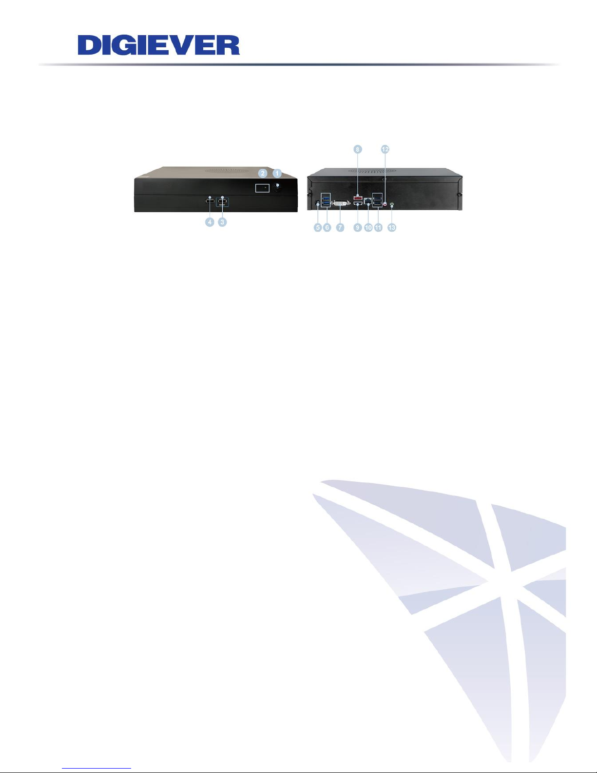
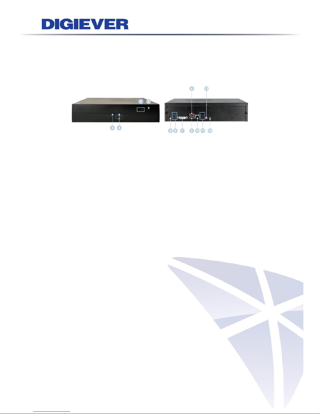
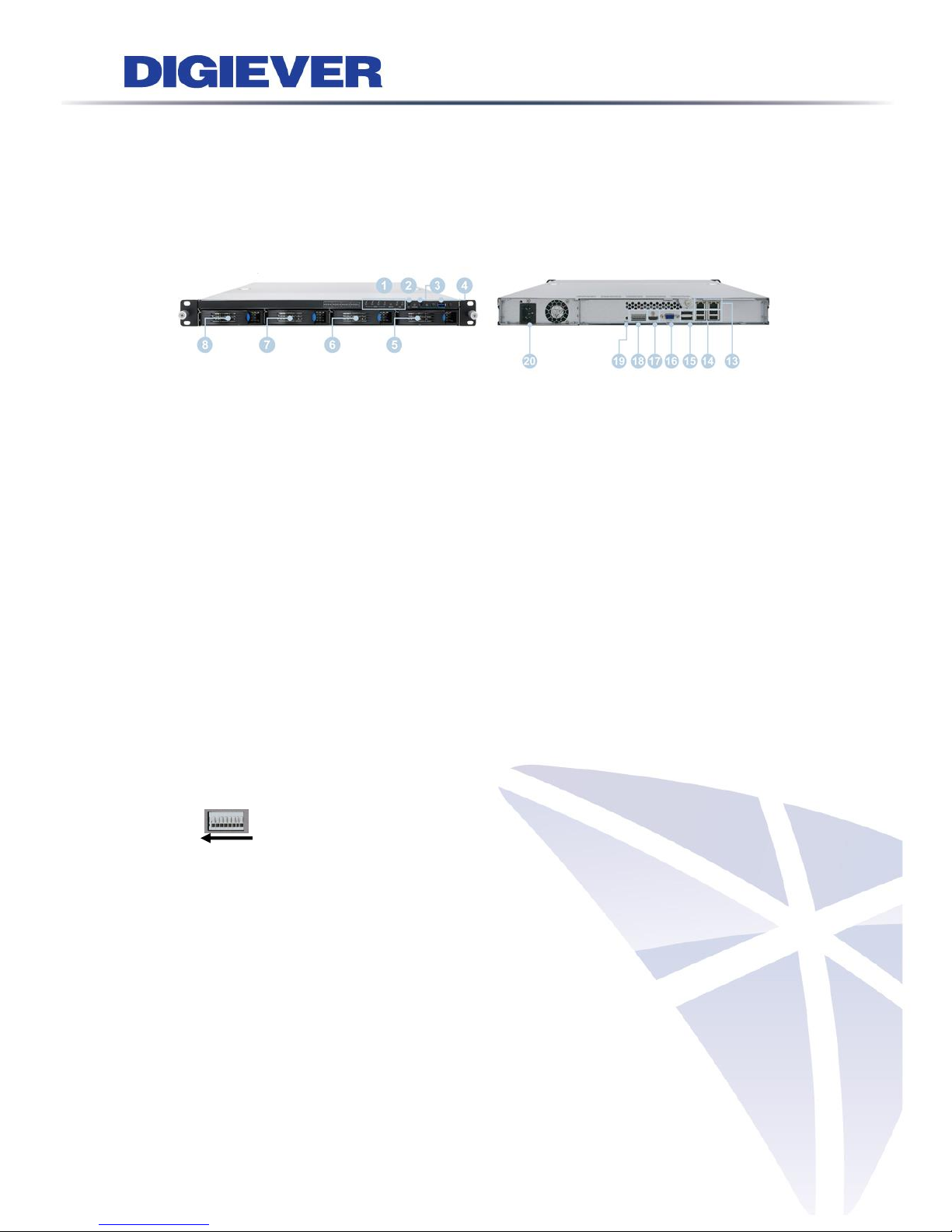
1.1.4 DS-2100 Pro Series
DS-2105 Pro/ DS-2109 Pro/ DS-2112 Pro/ DS-2116 Pro/ DS-2120 Pro/ DS-2125 Pro/
DS-2132 Pro/ DS-2136 Pro
Figure 1-4. Front & Rear View of DS-2100 Pro Series
1. Power button
2. LED indicators: HDD
3. USB 2.0 x1 (Support auto video backup)
4. USB 2.0 x1
5. Power connector
6. USB 3.0 x 2
7. DVI-I
8. eSATA x 1
9. HDMI x 1
10. Gigabit LAN
11. USB 2.0 x 2
12. Audio mic input (reserved)
13. Audio output (reserved)
Page 12
6
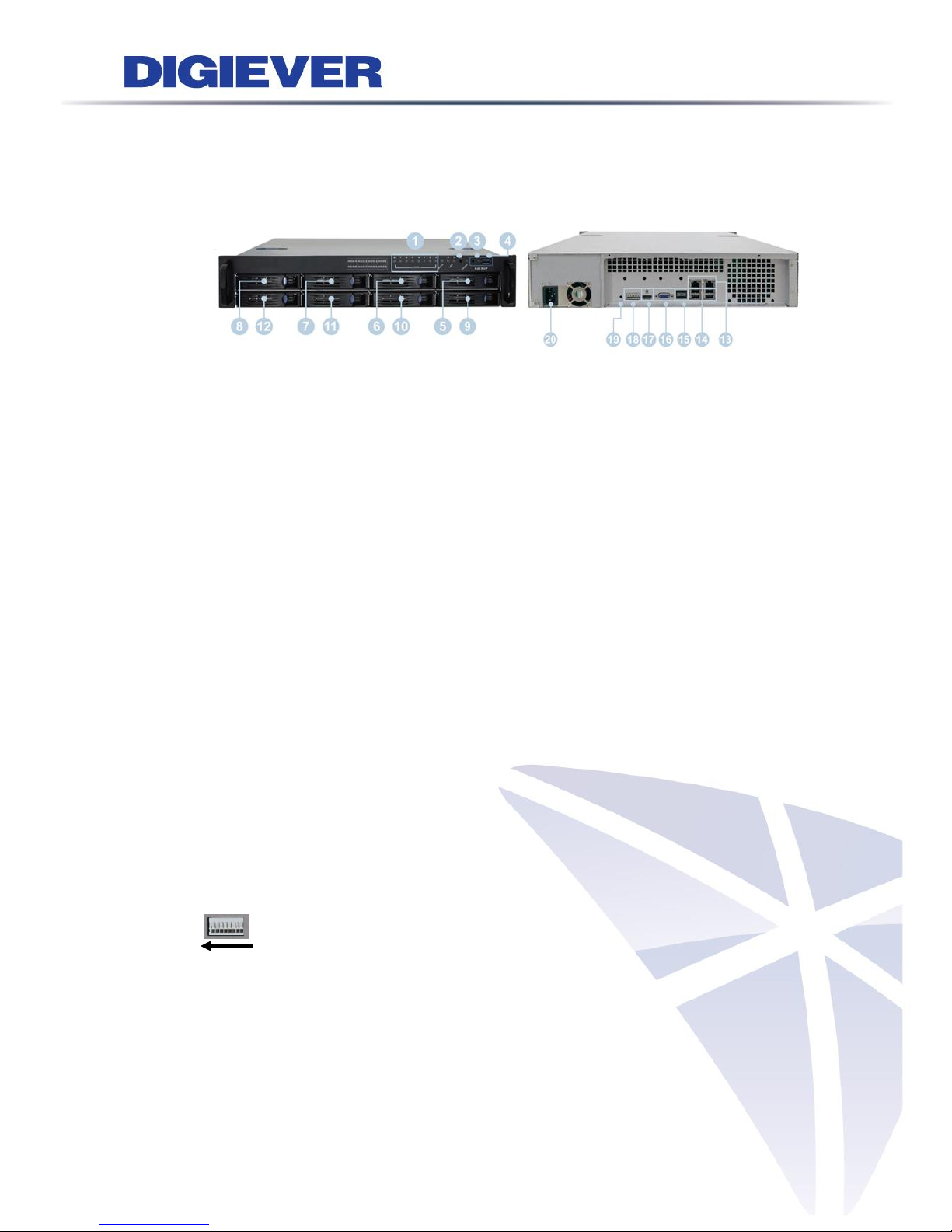
1.1.5 DS-4200 Pro Series
DS-4205 Pro/ DS-4209 Pro/ DS-4212 Pro/ DS-4216 Pro/ DS-4220 Pro/ DS-4225 Pro/
DS-4232 Pro/ DS-4236 Pro
Figure 1-5. Front & Rear View of DS-4200 Pro Series
1. LED indicators: LAN1, LAN2, eSATA, HDD1, HDD2, HDD3, HDD4
2. Power button
3. USB BACKUP button - Auto video backup
4. USB 2.0 x 1(Support auto video backup)
5. USB 2.0 x 1
6. HDD1
7. HDD2
8. HDD3
9. HDD4
10. Gigabit LAN x 2
11. USB 2.0 x 4
12. eSATA x 2
13. VGA output
14. HDMI output
15. DI/DO (4 in 2 out)
Top to bottom: Vcc5V, GND, DI-1, DI-2, DI-3, DI-4, DO-1, DO-2
16. Reset button*
17. Power connector
18. K-lock security slot
Page 13
7
1.1.6 DS-4200-RM Pro Series
DS-4209-RM Pro/ DS-4212-RM Pro/ DS-4216-RM Pro/ DS-4220-RM Pro/
DS-4225-RM Pro/ DS-4232-RM Pro/ DS-4236-RM Pro
Figure 1-6. Front & Rear View of DS-4200-RM Pro Series
1. LED indicators: LAN1, LAN2, eSATA, HDD1, HDD2, HDD3, HDD4
2. Power button
3. USB BACKUP button - Auto video backup
4. USB 3.0 x 1 (Support auto video backup)
5. HDD1
6. HDD2
7. HDD3
8. HDD4
9. Gigabit LAN x 2
10. USB 2.0 x 4
11. eSATA x 2
12. VGA output
13. HDMI output
14. DI/DO (4 in 2 out)
Right to left: Vcc5V, GND, DI-1, DI-2, DI-3, DI-4, DO1, DO2
15. Reset button*
16. Power connector
Page 14
8
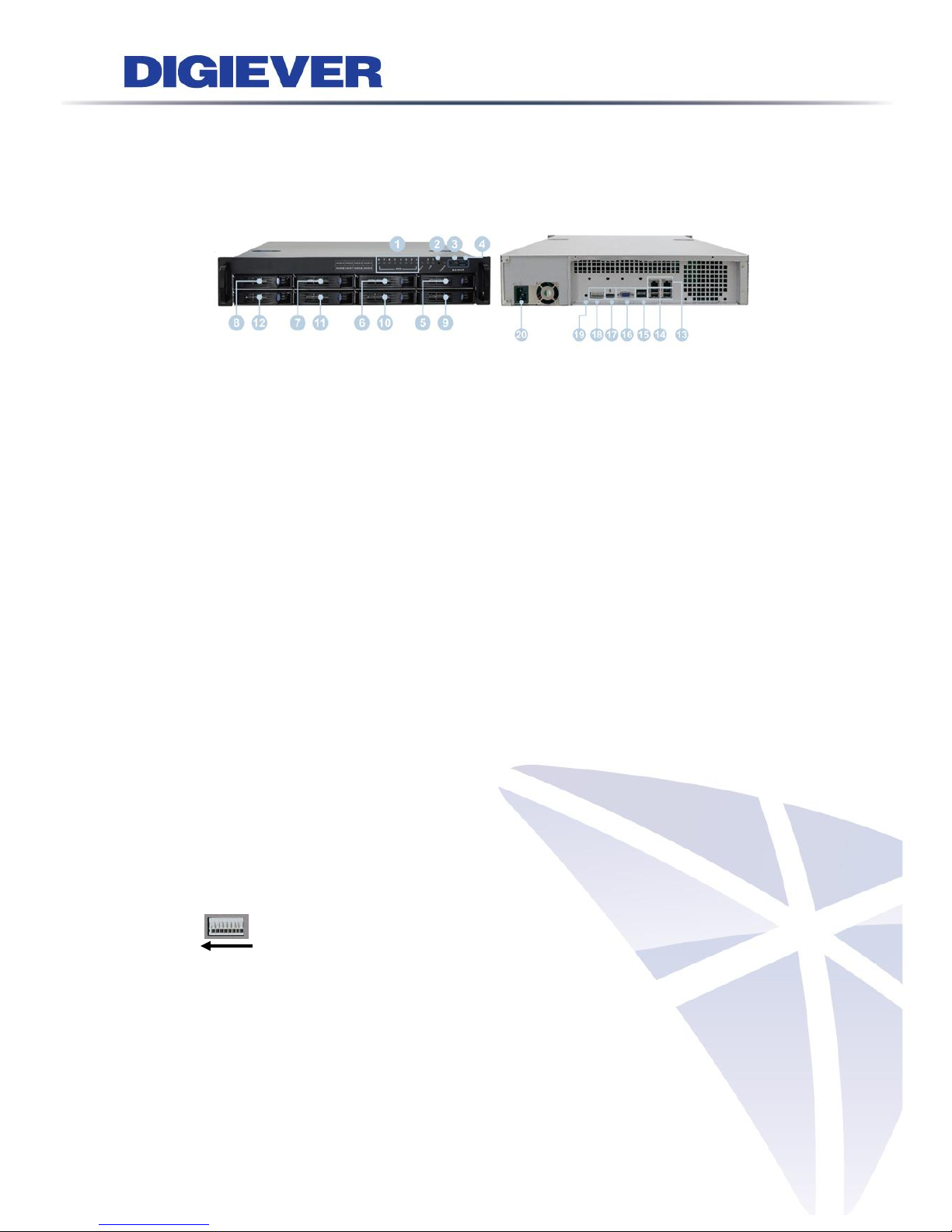
1.1.7 DS-8200-RM Pro Series
DS-8209-RM Pro/ DS-8212-RM Pro/ DS-8216-RM Pro/ DS-8220-RM Pro/
DS-8225-RM Pro/ DS-8232-RM Pro/ DS-8236-RM Pro
Figure 1-7. Front & Rear View of DS-8200-RM Pro Series
1. LED indicators: LAN1, LAN2, eSATA, HDD1, HDD2, HDD3, HDD4, HDD5, HDD6,
HDD7, HDD8
2. Power button
3. USB BACKUP button - Auto video backup
4. USB 3.0 x 1 (Support auto video backup)
5. HDD1
6. HDD2
7. HDD3
8. HDD4
9. HDD5
10. HDD6
11. HDD7
12. HDD8
13. Gigabit LAN x 2
14. USB 2.0 x 4
15. eSATA x 2
16. VGA output
17. HDMI output
18. DI/DO (4 in 2 out)
Right to left: Vcc5V, GND, DI-1, DI-2, DI-3, DI-4, DO1, DO2
19. Reset button*
20. Power connector
Page 15

9
1.1.8 DS-1100 Pro+ Series
DS-1105 Pro+/ DS-1109 Pro+/ DS-1112 Pro+/ DS-1116 Pro+/ DS-1120 Pro+/
DS-1125 Pro+/ DS-1132 Pro+/ DS-1136 Pro+/ DS-1142 Pro+/ DS-1149 Pro+/
DS-1156 Pro+/ DS-1164 Pro+
Figure 1-8. Front & Rear View of DS-1100 Pro+ Series
1. Power button
2. LED indicators: HDD
3. USB 2.0 x1 (Support auto video backup)
4. USB 2.0 x1
5. Power connector
6. USB 3.0 x 2
7. DVI-I
8. eSATA x 1
9. HDMI x 1
10. Gigabit LAN
11. USB 2.0 x 2
12. Audio mic input (reserved)
13. Audio output (reserved)
Page 16
10
1.1.9 DS-2100 Pro+ Series
DS-2105 Pro+/ DS-2109 Pro+/ DS-2112 Pro+/ DS-2116 Pro+/ DS-2120 Pro+/
DS-2125 Pro+/ DS-2132 Pro+/ DS-2136 Pro+/ DS-2142 Pro+/ DS-2149 Pro+/
DS-2156 Pro+/ DS-2164 Pro+
Figure 1-9. Front & Rear View of DS-2100 Pro+ Series
1. Power button
2. LED indicators: HDD
3. USB 2.0 x1 (Support auto video backup)
4. USB 2.0 x1
5. Power connector
6. USB 3.0 x 2
7. DVI-I
8. eSATA x 1
9. HDMI x 1
10. Gigabit LAN
11. USB 2.0 x 2
12. Audio mic input (reserved)
13. Audio output (reserved)
Page 17
11
1.1.10 DS-4200 Pro+ Series
DS-4205 Pro+/ DS-4209 Pro+/ DS-4212 Pro+/ DS-4216 Pro+/ DS-4220 Pro+/
DS-4225 Pro+/ DS-4232 Pro+/ DS-4236 Pro+/ DS-4242 Pro+/ DS-4249 Pro+/
DS-4256 Pro+/ DS-4264 Pro+
Figure 1-10. Front & Rear View of DS-4200 Pro+ Series
1. LED indicators: LAN1, LAN2, eSATA, HDD1, HDD2, HDD3, HDD4
2. Power button
3. USB BACKUP button - Auto video backup
4. USB 2.0 x 1(Support auto video backup)
5. USB 2.0 x 1
6. HDD1
7. HDD2
8. HDD3
9. HDD4
10. Gigabit LAN x 2
11. USB 2.0 x 4
12. eSATA x 2
13. VGA output
14. HDMI output
15. DI/DO (4 in 2 out)
Top to bottom: Vcc5V, GND, DI-1, DI-2, DI-3, DI-4, DO-1, DO-2
16. Reset button*
17. Power connector
18. K-lock security slot
Page 18
12
1.1.11 DS-4200-RM Pro+ Series
DS-4209-RM Pro+/ DS-4212-RM Pro+/ DS-4216-RM Pro+/ DS-4220-RM Pro+/
DS-4225-RM Pro+/ DS-4232-RM Pro+/ DS-4236-RM Pro+/ DS-4242-RM Pro+/
DS-4249-RM Pro+/ DS-4256-RM Pro+/ DS-4264-RM Pro+
Figure 1-11. Front & Rear View of DS-4200-RM Pro+ Series
1. LED indicators: LAN1, LAN2, eSATA, HDD1, HDD2, HDD3, HDD4
2. Power button
3. USB BACKUP button - Auto video backup
4. USB 3.0 x 1 (Support auto video backup)
5. HDD1
6. HDD2
7. HDD3
8. HDD4
9. Gigabit LAN x 2
10. USB 2.0 x 4
11. eSATA x 2
12. VGA output
13. HDMI output
14. DI/DO (4 in 2 out)
Right to left: Vcc5V, GND, DI-1, DI-2, DI-3, DI-4, DO1, DO2
15. Reset button*
16. Power connector
Page 19

13
1.1.12 DS-8200-RM Pro+ Series
DS-8209-RM Pro+/ DS-8212-RM Pro+/ DS-8216-RM Pro+/ DS-8220-RM Pro+/
DS-8225-RM Pro+/ DS-8232-RM Pro+/ DS-8236-RM Pro+/ DS-8242-RM Pro+/
DS-8249-RM Pro+/ DS-8256-RM Pro+/ DS-8264-RM Pro+
Figure 1-12. Front & Rear View of DS-8200-RM Pro+ Series
1. LED indicators: LAN1, LAN2, eSATA, HDD1, HDD2, HDD3, HDD4, HDD5, HDD6,
HDD7, HDD8
2. Power button
3. USB BACKUP button - Auto video backup
4. USB 3.0 x 1 (Support auto video backup)
5. HDD1
6. HDD2
7. HDD3
8. HDD4
9. HDD5
10. HDD6
11. HDD7
12. HDD8
13. Gigabit LAN x 2
14. USB 2.0 x 4
15. eSATA x 2
16. VGA output
17. HDMI output
18. DI/DO (4 in 2 out)
Right to left: Vcc5V, GND, DI-1, DI-2, DI-3, DI-4, DO1, DO2
19. Reset button*
20. Power connector
Page 20

14
1.1.13 DS-4300 Pro+ Series
DS-4332 Pro+/ DS-4336 Pro+/ DS-4342 Pro+/ DS-4349 Pro+/ DS-4356 Pro+/
DS-4364 Pro+
Figure 1-10. Front & Rear View of DS-4300 Pro+ Series
19. LED indicators: LAN1, LAN2, eSATA, HDD1, HDD2, HDD3, HDD4
20. Power button
21. USB BACKUP button - Auto video backup
22. USB 2.0 x 1(Support auto video backup)
23. USB 2.0 x 1
24. HDD1
25. HDD2
26. HDD3
27. HDD4
28. Gigabit LAN x 2
29. USB 2.0 x 4
30. eSATA x 2
31. VGA output
32. HDMI output
33. DI/DO (4 in 2 out)
Top to bottom: Vcc5V, GND, DI-1, DI-2, DI-3, DI-4, DO-1, DO-2
34. Reset button*
35. Power connector
36. K-lock security slot
Page 21
15
1.1.14 DS-4300-RM Pro+ Series
DS-4332-RM Pro+/ DS-4336-RM Pro+/ DS-4342-RM Pro+/ DS-4349-RM Pro+/
DS-4356-RM Pro+/ DS-4364-RM Pro+
Figure 1-11. Front & Rear View of DS-4300-RM Pro+ Series
17. LED indicators: LAN1, LAN2, eSATA, HDD1, HDD2, HDD3, HDD4
18. Power button
19. USB BACKUP button - Auto video backup
20. USB 3.0 x 1 (Support auto video backup)
21. HDD1
22. HDD2
23. HDD3
24. HDD4
25. Gigabit LAN x 2
26. USB 2.0 x 4
27. eSATA x 2
28. VGA output
29. HDMI output
30. DI/DO (4 in 2 out)
Right to left: Vcc5V, GND, DI-1, DI-2, DI-3, DI-4, DO1, DO2
31. Reset button*
32. Power connector
Page 22
16
1.1.15 DS-8300-RM Pro+ Series
DS-8342-RM Pro+/ DS-8349-RM Pro+/ DS-8356-RM Pro+/ DS-8364-RM Pro+
Figure 1-13. Front & Rear View of DS-8300-RM Pro+ Series
21. LED indicators: LAN1, LAN2, eSATA, HDD1, HDD2, HDD3, HDD4, HDD5, HDD6,
HDD7, HDD8
22. Power button
23. USB BACKUP button - Auto video backup
24. USB 3.0 x 1 (Support auto video backup)
25. HDD1
26. HDD2
27. HDD3
28. HDD4
29. HDD5
30. HDD6
31. HDD7
32. HDD8
33. Gigabit LAN x 2
34. USB 2.0 x 4
35. eSATA x 2
36. VGA output
37. HDMI output
38. DI/DO (4 in 2 out)
Right to left: Vcc5V, GND, DI-1, DI-2, DI-3, DI-4, DO1, DO2
39. Reset button*
40. Power connector
Page 23
17
1.2 LED Indicators Status
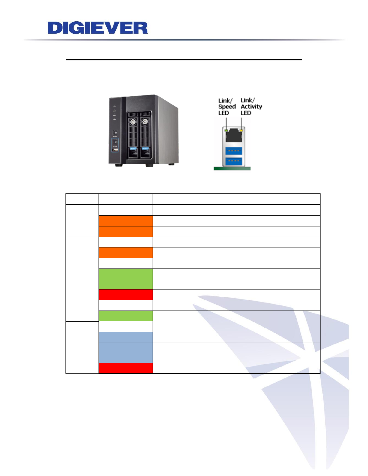
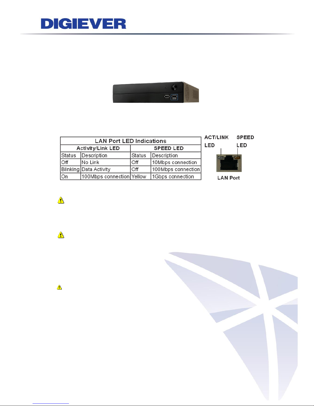
1.2.1 DS-2000 Series
DS-2005/ DS-2009/ DS-2012/ DS-2016/ DS-2020/ DS-2025/ DS-2032
Figure 2-1. DS-2000 Series Front Panel & RJ-45 Port
LED on Front Panel
LED
LED Color & Status
Indicate
LAN
Off
LAN Link is not established
Orange
LAN Link is established
Orange blinking
LAN is being accessed
eSATA
Off
No data transmission
Orange blinking
The eSATA device is being accessed
HDD1
HDD2
Off
Hard disk drive device is not established
Green
Hard disk drive is ready to be accessed
Green blinking
Hard disk drive data is being accessed
Red
Hard disk drive failure and need to be removed
Power
Off
Power Off
Green
Power On
BACKUP
Off
USB device is not detected
Blue
USB device is ready
Blue blinking
NVR data is being copied to the USB device
(Blinking with 1Hz)
Red
Backup error occurs
Page 24
18
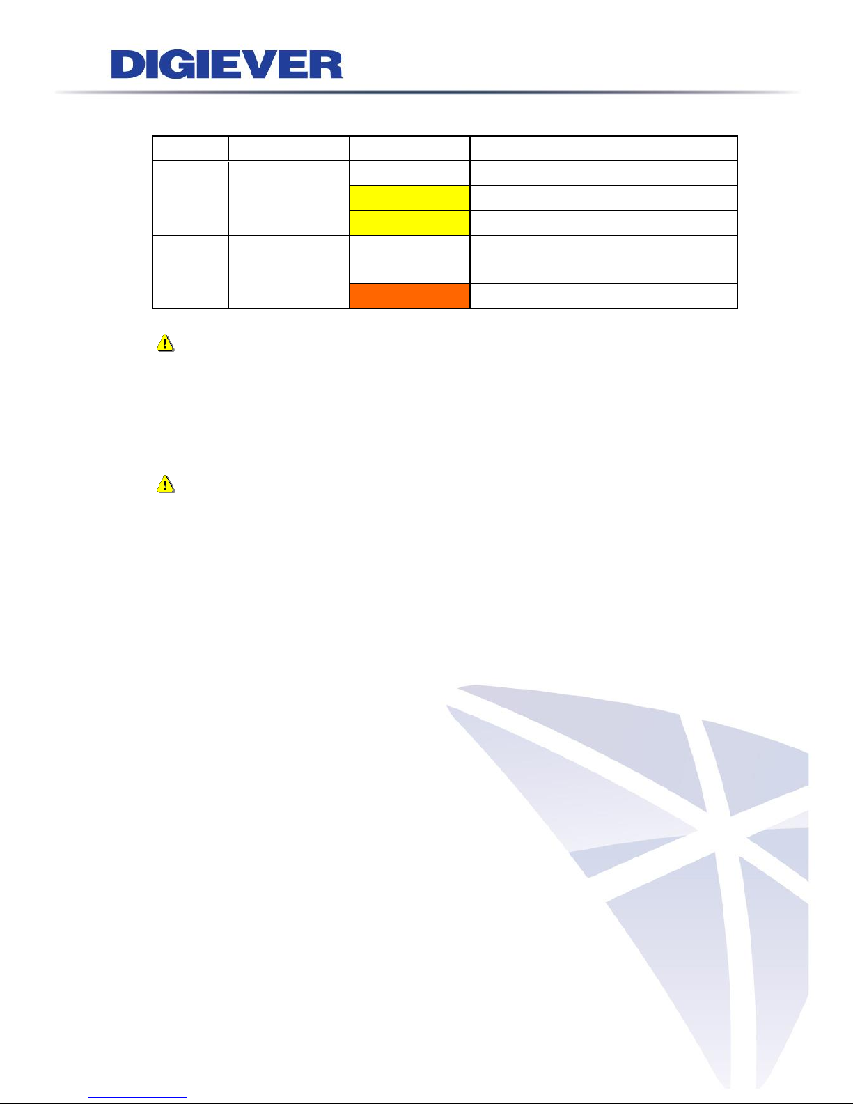
LED on RJ-45 Port on Rear Panel
LED
LED Position
LED Status
Indicate
LAN
Link/Activity
(Right LED)
Off
LAN Link is not established
Yellow
LAN Link is established
Yellow blinking
LAN Activity is occurring
LAN
Speed
(Left LED)
Off
10M/100Mbps connection or no
connection
Orange
1000Mbps connection
Note:
**USB BACKUP will beep and process after long pressing BACKUP button for 3
seconds.
**To turn off your NVR, long pressing power button at least 2 seconds.
**To turn on your NVR, long pressing power button at least 3 seconds.
Note: Once users press reset button, configuration of Camera Setting, Recording
Settings, Event & Action Setting, E-Mail Settings, and Server Settings will reset to
default. It is advised to backup system configurations. For more information, refer to
detail information in user manual 5.6.3 Save/Load Configuration.
Page 25
19
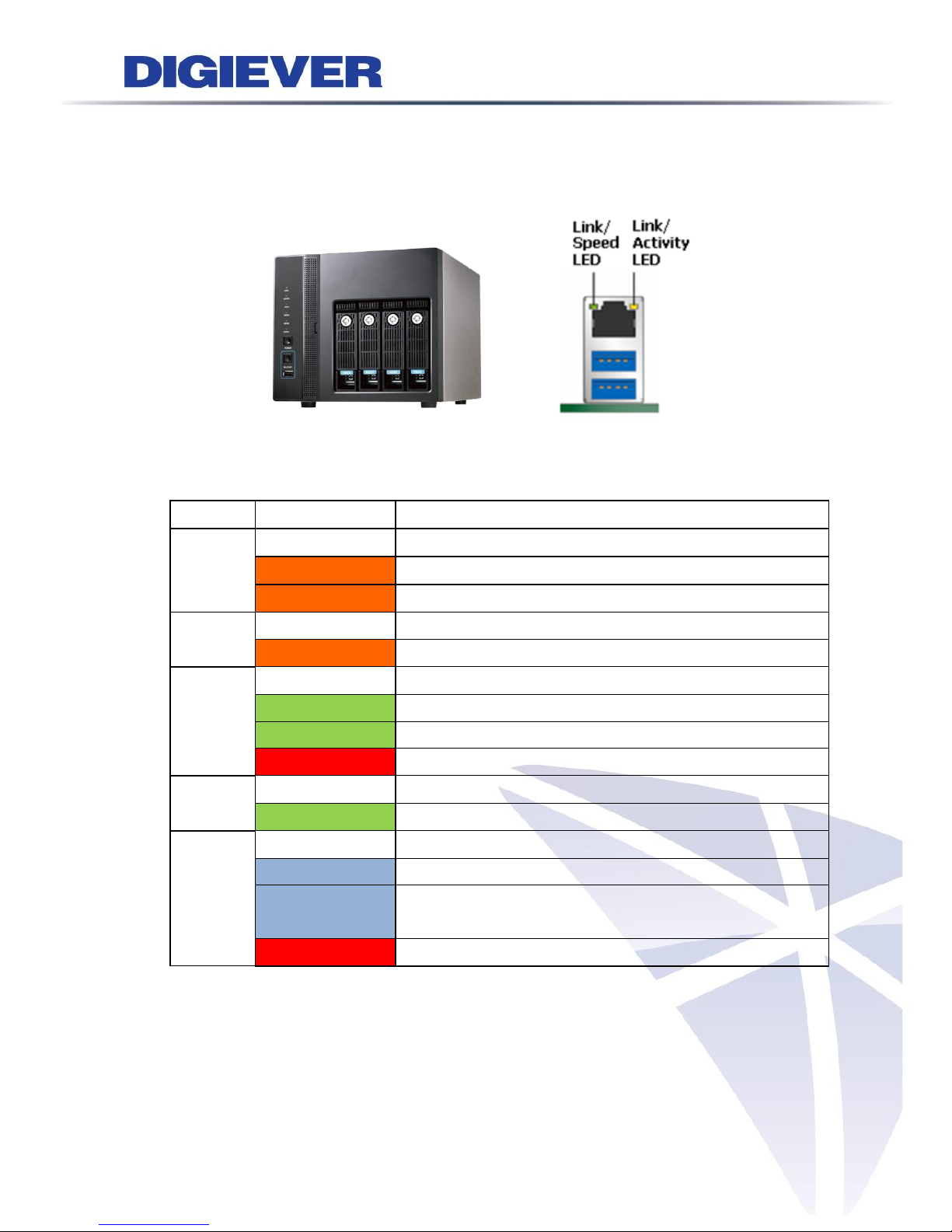
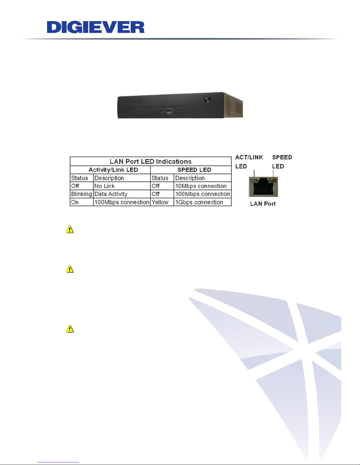
1.2.2 DS-4000 Series
DS-4005/ DS-4009/ DS-4012/ DS-4016/ DS-4020/ DS-4025/ DS-4032
Figure 2-2. DS-4000 Series Front Panel & RJ-45 Port
LED on Front Panel
LED
LED Color & Status
Indicate
LAN
Off
LAN Link is not established
Orange
LAN Link is established
Orange blinking
LAN is being accessed
eSATA
Off
No data transmission
Orange blinking
The eSATA device is being accessed
HDD1
HDD2
HDD3
HDD4
Off
Hard disk drive device is not established
Green
Hard disk drive is ready to be accessed
Green blinking
Hard disk drive data is being accessed
Red
Hard disk drive failure and need to be removed
Power
Off
Power Off
Green
Power On
BACKUP
Off
USB device is not detected
Blue
USB device is ready
Blue blinking
NVR data is being copied to the USB device
(Blinking with 1Hz)
Red
Backup error occurs
Page 26
20
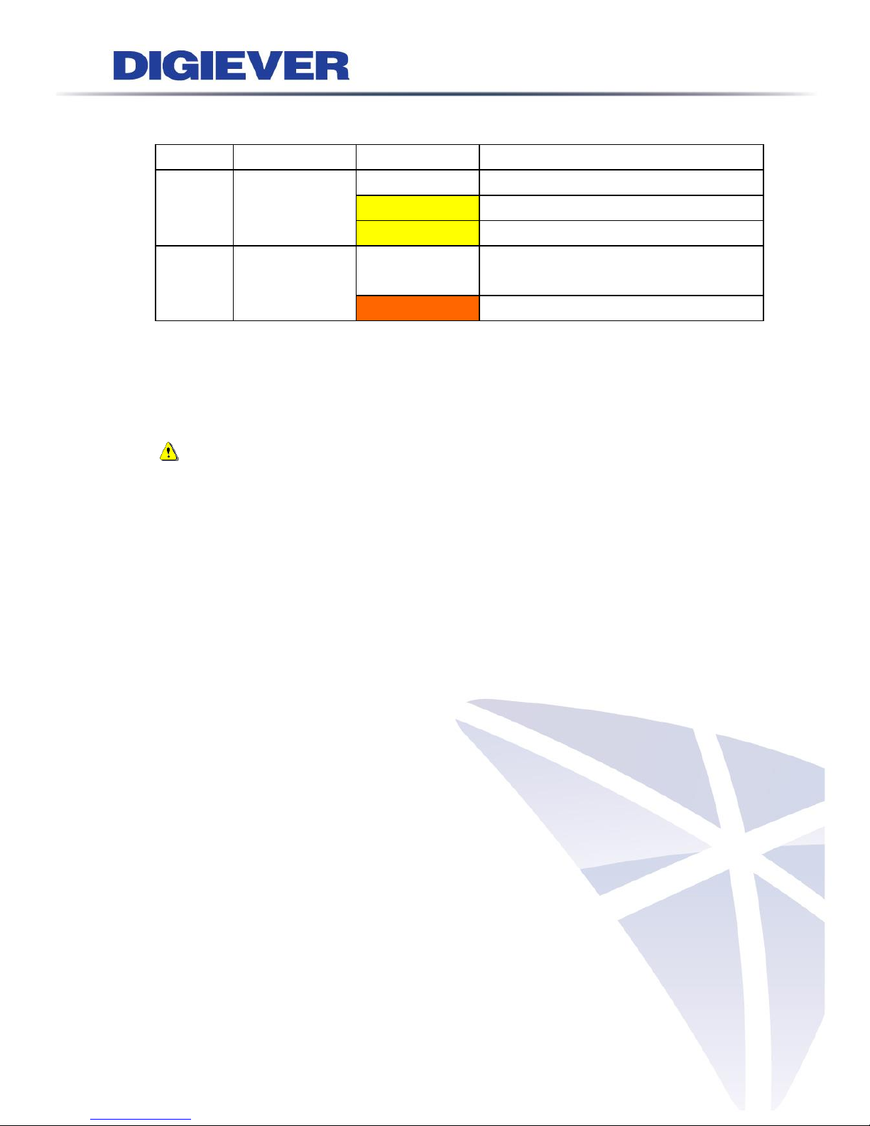
LED on RJ-45 Port on Rear Panel
LED
LED Position
LED Status
Indicate
LAN
Link/Activity
(Right LED)
Off
LAN Link is not established
Yellow
LAN Link is established
Yellow blinking
LAN Activity is occurring
LAN
Speed
(Left LED)
Off
10M/100Mbps connection or no
connection
Orange
1000Mbps connection
*USB BACKUP will start and beep after 3 seconds user presses BACKUP button.
**To turn off NVR, users need to press power button at least 2 seconds.
***To turn on NVR, users need to press power button at least 3 seconds.
Note: Once users press reset button, configuration of Camera Setting, Recording
Settings, Event & Action Setting, E-Mail Settings, and Server Settings will reset to
default. It is advised to backup system configurations. For more information, refer to
detail information in user manual 5.6.3 Save/Load Configuration.
Page 27
21
1.2.3 DS-1100 Pro Series
DS-1105 Pro/ DS-1109 Pro/ DS-1112 Pro/ DS-1116 Pro/ DS-1120 Pro/ DS-1125 Pro/
DS-1132 Pro/ DS-1136 Pro
Figure 2-3. DS-1100 Pro Series Front Panel
Note:
**To turn off your NVR, long pressing power button at least 2 seconds.
**To turn on your NVR, long pressing power button at least 3 seconds.
Note: To reset to default, please follow below methods:
Press the power button twice with the interval of one second. In other words, please
press the power button in the 1st second and press the power button again in the 2nd
second. It will be easier to operate the reset to default with the assistance of watch
or clock.
Note: Once users press reset button, configuration of Camera Setting,
Recording Settings, Event & Action Setting, E-Mail Settings, and Server Settings
will reset to default. It is advised to backup system configurations. For more
information, refer to detail information in user manual 5.6.3 Save/Load
Configuration.
Page 28
22
1.2.4 DS-2100 Pro Series
DS-2105 Pro/ DS-2109 Pro/ DS-2112 Pro/ DS-2116 Pro/ DS-2120 Pro/ DS-2125 Pro/
DS-2132 Pro/ DS-2136 Pro
Figure 2-4. DS-2100 Series Front Panel
Note:
**To turn off your NVR, long pressing power button at least 2 seconds.
**To turn on your NVR, long pressing power button at least 3 seconds.
Note: To reset to default, please follow below methods:
Press the power button twice with the interval of one second. In other words, please
press the power button in the 1st second and press the power button again in the 2nd
second. It will be easier to operate the reset to default with the assistance of watch
or clock.
Note: Once users press reset button, configuration of Camera Setting, Recording
Settings, Event & Action Setting, E-Mail Settings, and Server Settings will reset to
default. It is advised to backup system configurations. For more information, refer to
detail information in user manual 5.6.3 Save/Load Configuration.
Page 29
23
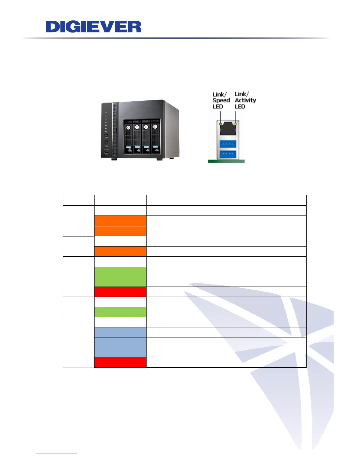
1.2.5 DS-4200 Pro Series
DS-4205Pro/ DS-4209Pro/ DS-4212Pro/ DS-4216Pro/ DS-4220Pro/ DS-4225Pro/
DS-4232 Pro/ DS-4236 Pro
Figure 2-5. DS-4200 Pro Series Front Panel & RJ-45 Port
LED on Front Panel
LED
LED Color & Status
Indicate
LAN
Off
LAN Link is not established
Orange
LAN Link is established
Orange blinking
LAN is being accessed
eSATA
Off
No data transmission
Orange blinking
The eSATA device is being accessed
HDD1
HDD2
HDD3
HDD4
Off
Hard disk drive device is not established
Green
Hard disk drive is ready to be accessed
Green blinking
Hard disk drive data is being accessed
Red
Hard disk drive failure and need to be removed
Power
Off
Power Off
Green
Power On
BACKUP
Off
USB device is not detected
Blue
USB device is ready
Blue blinking
NVR data is being copied to the USB device
(Blinking with 1Hz)
Red
Backup error occurs
Page 30
24
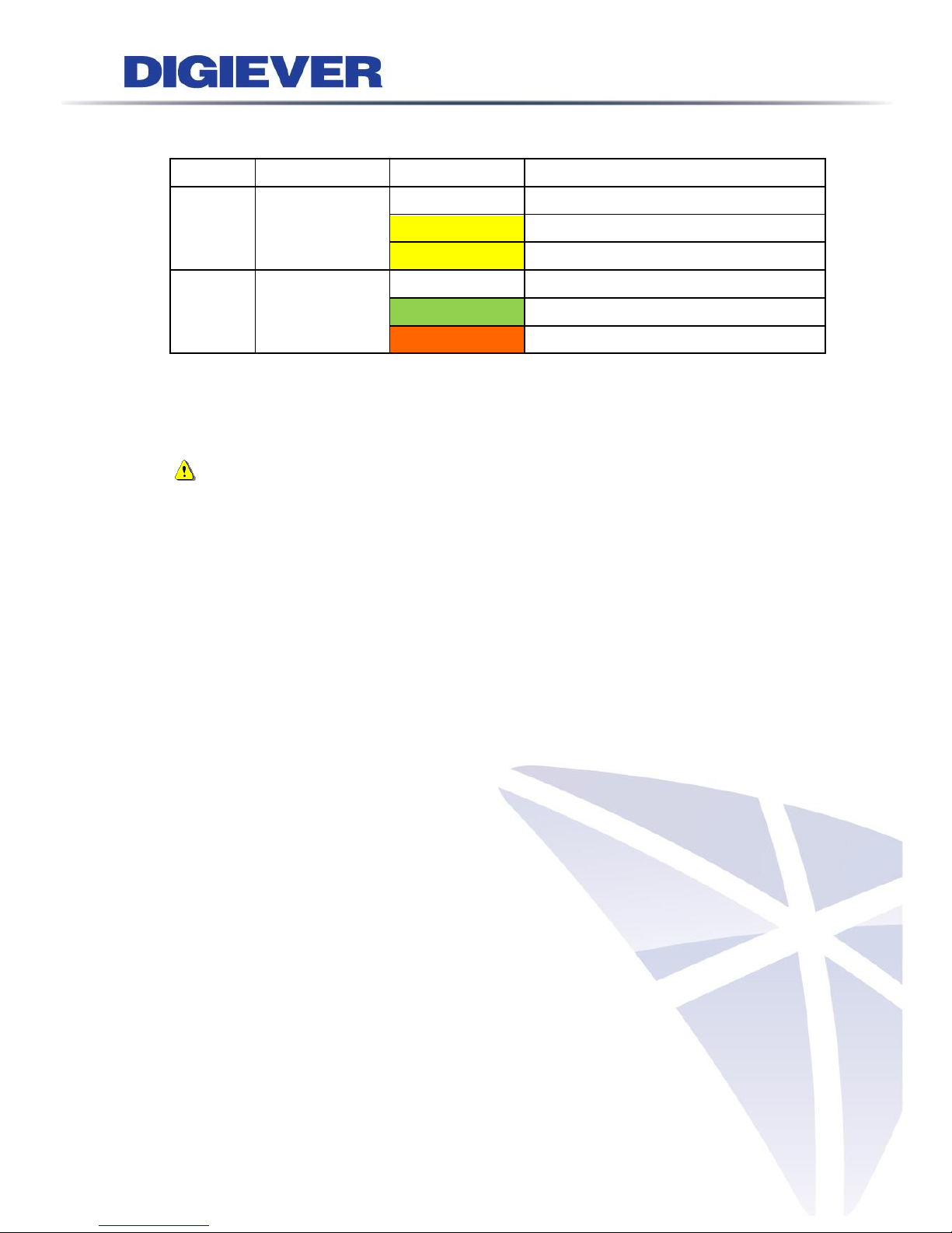
LED on RJ-45 Connection at Rear Panel
LED
LED Position
LED/State
Indicate
LAN1
LAN2
Link/Activity
(Right LED)
Off
LAN Link is not established
Yellow
LAN Link is established
Yellow Blinking
LAN activity is occurring
LAN1
LAN2
Speed
(Left LED)
Off
10Mbps connection or no connection
Green
100Mbps connection
Orange
1000Mbps connection
*USB BACKUP will start and beep after 3 seconds user presses BACKUP button.
**To turn off NVR, user needs to press power button at least 2 seconds.
Note: Once users press reset button, configuration of Camera Setting, Recording
Settings, Event & Action Setting, E-Mail Settings, and Server Settings will reset to
default. It is advised to backup system configurations. For more information, refer to
detail information in user manual 5.6.3 Save/Load Configuration.
Page 31

25
1.2.6 DS-4200-RM Pro Series
DS-4209-RM Pro/ DS-4212-RM Pro/ DS-4216-RM Pro/DS-4220-RM Pro/ DS-4225-RM
Pro/ DS-4232-RM Pro/ DS-4236-RM Pro
Figure 2-6. Front View of DS-4200-RM Pro Series & RJ-45 Port
LED on Front Panel
LED
LED Color & Status
Indicate
LAN
Off
LAN Link is not established
Orange
LAN Link is established
Orange blinking
LAN is being accessed
eSATA
Off
No data transmission
Orange blinking
The eSATA device is being accessed
HDD1
HDD2
HDD3
HDD4
Off
Hard disk drive device is not established
Green
Hard disk drive is ready to be accessed
Green blinking
Hard disk drive data is being accessed
Red
Hard disk drive failure and need to be removed
Power
Off
Power Off
Green
Power On
BACKUP
Off
USB device is not detected
Blue
USB device is ready
Blue blinking
NVR data is being copied to the USB device
(Blinking with 1Hz)
Red
Backup error occurs
Page 32

26
LED on RJ-45 Connection at Rear Panel
LED
LED Position
LED/State
Indicate
LAN1
LAN2
Link/Activity
(Right LED)
Off
LAN Link is not established
Yellow
LAN Link is established
Yellow Blinking
LAN activity is occurring
LAN1
LAN2
Speed
(Left LED)
Off
10Mbps connection or no connection
Green
100Mbps connection
Orange
1000Mbps connection
*USB BACKUP will start and beep after 3 seconds user presses BACKUP button.
**To turn off NVR, user needs to press power button at least 2 seconds.
*** The LED in the HDD trays are reserved.
Note: Once users press reset button, configuration of Camera Setting, Recording
Settings, Event & Action Setting, E-Mail Settings, and Server Settings will reset to
default. It is advised to backup system configurations. For more information, refer to
detail information in user manual 5.6.3 Save/Load Configuration.
Page 33

27
1.2.7 DS-8200-RM Pro Series
DS-8209-RM Pro/ DS-8212-RM Pro/ DS-8216-RM Pro/DS-8220-RM Pro/ DS-8225-RM
Pro/DS-8232-RM Pro/ DS-82326-RM Pro
Figure 2-7. Front View of DS-8200-RM Pro Series & RJ-45 Port
LED on Front Panel
LED
LED Color & Status
Indicate
LAN
Off
LAN Link is not established
Orange
LAN Link is established
Orange blinking
LAN is being accessed
eSATA
Off
No data transmission
Orange blinking
The eSATA device is being accessed
HDD1
HDD2
HDD3
HDD4
HDD5
HDD6
HDD7
HDD8
Off
Hard disk drive device is not established
Green
Hard disk drive is ready to be accessed
Green blinking
Hard disk drive data is being accessed
Red
Hard disk drive failure and need to be removed
Power
Off
Power Off
Green
Power On
BACKUP
Off
USB device is not detected
Blue
USB device is ready
Blue blinking
NVR data is being copied to the USB device
(Blinking with 1Hz)
Red
Backup error occurs
Page 34

28
LED on RJ-45 Connection at Rear Panel
LED
LED Position
LED/State
Indicate
LAN1
LAN2
Link/Activity
(Right LED)
Off
LAN Link is not established
Yellow
LAN Link is established
Yellow Blinking
LAN activity is occurring
LAN1
LAN2
Speed
(Left LED)
Off
10Mbps connection or no connection
Green
100Mbps connection
Orange
1000Mbps connection
*USB BACKUP will start and beep after 3 seconds user presses BACKUP button.
**To turn off NVR, user needs to press power button at least 2 seconds.
*** The LED in the HDD trays are reserved.
Note: Once users press reset button, configuration of Camera Setting, Recording
Settings, Event & Action Setting, E-Mail Settings, and Server Settings will reset to
default. It is advised to backup system configurations. For more information, refer to
detail information in user manual 5.6.3 Save/Load Configuration.
Page 35

29
1.2.8 DS-1100 Pro+ Series
DS-1105 Pro+/ DS-1109 Pro+/ DS-1112 Pro+/ DS-1116 Pro+/ DS-1120 Pro+/
DS-1125 Pro+/ DS-1132 Pro+/ DS-1136 Pro+/ DS-1142 Pro+/ DS-1149 Pro+/
DS-1156 Pro+/ DS-1164 Pro+
Figure 2-8. DS-1100 Pro+ Series Front Panel
Note:
**To turn off your NVR, long pressing power button at least 2 seconds.
**To turn on your NVR, long pressing power button at least 3 seconds.
Note: To reset to default, please follow below methods:
Press the power button twice with the interval of one second. In other words, please
press the power button in the 1st second and press the power button again in the 2nd
second. It will be easier to operate the reset to default with the assistance of watch
or clock.
Note: Once users press reset button, configuration of Camera Setting, Recording
Settings, Event & Action Setting, E-Mail Settings, and Server Settings will reset to
default. It is advised to backup system configurations. For more information, refer to
detail information in user manual 5.6.3 Save/Load Configuration.
Page 36

30
1.2.9 DS-2100 Pro+ Series
DS-2105 Pro+/ DS-2109 Pro+/ DS-2112 Pro+/ DS-2116 Pro+/ DS-2120 Pro+/
DS-2125 Pro+/ DS-2132 Pro+/ DS-2136 Pro+/ DS-2142 Pro+/ DS-2149 Pro+/
DS-2156 Pro+/ DS-2164 Pro+
Figure 2-9. DS-2100 Pro+ Series Front Panel
Note:
**To turn off your NVR, long pressing power button at least 2 seconds.
**To turn on your NVR, long pressing power button at least 3 seconds.
Note: To reset to default, please follow below methods:
Press the power button twice with the interval of one second. In other words, please
press the power button in the 1st second and press the power button again in the 2nd
second. It will be easier to operate the reset to default with the assistance of watch
or clock.
Note: Once users press reset button, configuration of Camera Setting, Recording
Settings, Event & Action Setting, E-Mail Settings, and Server Settings will reset to
default. It is advised to backup system configurations. For more information, refer to
detail information in user manual 5.6.3 Save/Load Configuration.
Page 37

31
1.2.10 DS-4200 Pro+ Series
DS-4205 Pro+/ DS-4209 Pro+/ DS-4212 Pro+/ DS-4216 Pro+/ DS-4220 Pro+/
DS-4225 Pro+/ DS-4232 Pro+/ DS-4236 Pro+/ DS-4242 Pro+/ DS-4249 Pro+/
DS-4256 Pro+/ DS-4264 Pro+
Figure 2-10. DS-4200 Pro+ Series Front Panel & RJ-45 Port
LED on Front Panel
LED
LED Color & Status
Indicate
LAN
Off
LAN Link is not established
Orange
LAN Link is established
Orange blinking
LAN is being accessed
eSATA
Off
No data transmission
Orange blinking
The eSATA device is being accessed
HDD1
HDD2
HDD3
HDD4
Off
Hard disk drive device is not established
Green
Hard disk drive is ready to be accessed
Green blinking
Hard disk drive data is being accessed
Red
Hard disk drive failure and need to be removed
Power
Off
Power Off
Green
Power On
BACKUP
Off
USB device is not detected
Blue
USB device is ready
Blue blinking
NVR data is being copied to the USB device
(Blinking with 1Hz)
Red
Backup error occurs
Page 38

32
LED on RJ-45 Connection at Rear Panel
LED
LED Position
LED/State
Indicate
LAN1
LAN2
Link/Activity
(Right LED)
Off
LAN Link is not established
Yellow
LAN Link is established
Yellow Blinking
LAN activity is occurring
LAN1
LAN2
Speed
(Left LED)
Off
10Mbps connection or no connection
Green
100Mbps connection
Orange
1000Mbps connection
*USB BACKUP will start and beep after 3 seconds user presses BACKUP button.
**To turn off NVR, user needs to press power button at least 2 seconds.
Note: Once users press reset button, configuration of Camera Setting, Recording
Settings, Event & Action Setting, E-Mail Settings, and Server Settings will reset to
default. It is advised to backup system configurations. For more information, refer to
detail information in user manual 5.6.3 Save/Load Configuration.
Page 39

33
1.2.11 DS-4200-RM Pro+ Series
DS-4209-RM Pro+/ DS-4212-RM Pro+/ DS-4216-RM Pro+/ DS-4220-RM Pro+/
DS-4225-RM Pro+/ DS-4232-RM Pro+/ DS-4236-RM Pro+/ DS-4242-RM Pro+/
DS-4249-RM Pro+/ DS-4256-RM Pro+/ DS-4264-RM Pro+
Figure 2-11. Front View of DS-4200-RM Pro+ Series & RJ-45 Port
LED on Front Panel
LED
LED Color & Status
Indicate
LAN
Off
LAN Link is not established
Orange
LAN Link is established
Orange blinking
LAN is being accessed
eSATA
Off
No data transmission
Orange blinking
The eSATA device is being accessed
HDD1
HDD2
HDD3
HDD4
Off
Hard disk drive device is not established
Green
Hard disk drive is ready to be accessed
Green blinking
Hard disk drive data is being accessed
Red
Hard disk drive failure and need to be removed
Power
Off
Power Off
Green
Power On
BACKUP
Off
USB device is not detected
Blue
USB device is ready
Blue blinking
NVR data is being copied to the USB device
(Blinking with 1Hz)
Red
Backup error occurs
Page 40

34
LED on RJ-45 Connection at Rear Panel
LED
LED Position
LED/State
Indicate
LAN1
LAN2
Link/Activity
(Right LED)
Off
LAN Link is not established
Yellow
LAN Link is established
Yellow Blinking
LAN activity is occurring
LAN1
LAN2
Speed
(Left LED)
Off
10Mbps connection or no connection
Green
100Mbps connection
Orange
1000Mbps connection
*USB BACKUP will start and beep after 3 seconds user presses BACKUP button.
**To turn off NVR, user needs to press power button at least 2 seconds.
*** The LED in the HDD trays are reserved.
Note: Once users press reset button, configuration of Camera Setting, Recording
Settings, Event & Action Setting, E-Mail Settings, and Server Settings will reset to
default. It is advised to backup system configurations. For more information, refer to
detail information in user manual 5.6.3 Save/Load Configuration.
Page 41

35
1.2.12 DS-8200-RM Pro+ Series
DS-8209-RM Pro+/ DS-8212-RM Pro+/ DS-8216-RM Pro+/ DS-8220-RM Pro+/
DS-8225-RM Pro+/ DS-8232-RM Pro+/ DS-8236-RM Pro+/ DS-8242-RM Pro+/
DS-8249-RM Pro+/ DS-8256-RM Pro+/ DS-8264-RM Pro+
Figure 2-12. Front View of DS-8200-RM Pro+ Series & RJ-45 Port
LED on Front Panel
LED
LED Color & Status
Indicate
LAN
Off
LAN Link is not established
Orange
LAN Link is established
Orange blinking
LAN is being accessed
eSATA
Off
No data transmission
Orange blinking
The eSATA device is being accessed
HDD1
HDD2
HDD3
HDD4
HDD5
HDD6
HDD7
HDD8
Off
Hard disk drive device is not established
Green
Hard disk drive is ready to be accessed
Green blinking
Hard disk drive data is being accessed
Red
Hard disk drive failure and need to be removed
Power
Off
Power Off
Green
Power On
BACKUP
Off
USB device is not detected
Blue
USB device is ready
Blue blinking
NVR data is being copied to the USB device
(Blinking with 1Hz)
Red
Backup error occurs
Page 42

36
LED on RJ-45 Connection at Rear Panel
LED
LED Position
LED/State
Indicate
LAN1
LAN2
Link/Activity
(Right LED)
Off
LAN Link is not established
Yellow
LAN Link is established
Yellow Blinking
LAN activity is occurring
LAN1
LAN2
Speed
(Left LED)
Off
10Mbps connection or no connection
Green
100Mbps connection
Orange
1000Mbps connection
*USB BACKUP will start and beep after 3 seconds user presses BACKUP button.
**To turn off NVR, user needs to press power button at least 2 seconds.
*** The LED in the HDD trays are reserved.
Note: Once users press reset button, configuration of Camera Setting, Recording
Settings, Event & Action Setting, E-Mail Settings, and Server Settings will reset to
default. It is advised to backup system configurations. For more information, refer to
detail information in user manual 5.6.3 Save/Load Configuration.
Page 43

37
1.2.13 DS-4300 Pro+ Series
DS-4332 Pro+/ DS-4336 Pro+/ DS-4342 Pro+/ DS-4349 Pro+/ DS-4356 Pro+/
DS-4364 Pro+
Figure 2-10. DS-4300 Pro+ Series Front Panel & RJ-45 Port
LED on Front Panel
LED
LED Color & Status
Indicate
LAN
Off
LAN Link is not established
Orange
LAN Link is established
Orange blinking
LAN is being accessed
eSATA
Off
No data transmission
Orange blinking
The eSATA device is being accessed
HDD1
HDD2
HDD3
HDD4
Off
Hard disk drive device is not established
Green
Hard disk drive is ready to be accessed
Green blinking
Hard disk drive data is being accessed
Red
Hard disk drive failure and need to be removed
Power
Off
Power Off
Green
Power On
BACKUP
Off
USB device is not detected
Blue
USB device is ready
Blue blinking
NVR data is being copied to the USB device
(Blinking with 1Hz)
Red
Backup error occurs
Page 44

38
LED on RJ-45 Connection at Rear Panel
LED
LED Position
LED/State
Indicate
LAN1
LAN2
Link/Activity
(Right LED)
Off
LAN Link is not established
Yellow
LAN Link is established
Yellow Blinking
LAN activity is occurring
LAN1
LAN2
Speed
(Left LED)
Off
10Mbps connection or no connection
Green
100Mbps connection
Orange
1000Mbps connection
*USB BACKUP will start and beep after 3 seconds user presses BACKUP button.
**To turn off NVR, user needs to press power button at least 2 seconds.
Note: Once users press reset button, configuration of Camera Setting, Recording
Settings, Event & Action Setting, E-Mail Settings, and Server Settings will reset to
default. It is advised to backup system configurations. For more information, refer to
detail information in user manual 5.6.3 Save/Load Configuration.
Page 45

39
1.2.14 DS-4300-RM Pro+ Series
DS-4332-RM Pro+/ DS-4336-RM Pro+/ DS-4342-RM Pro+/ DS-4349-RM Pro+/
DS-4356-RM Pro+/ DS-4364-RM Pro+
Figure 2-11. Front View of DS-4300-RM Pro+ Series & RJ-45 Port
LED on Front Panel
LED
LED Color & Status
Indicate
LAN
Off
LAN Link is not established
Orange
LAN Link is established
Orange blinking
LAN is being accessed
eSATA
Off
No data transmission
Orange blinking
The eSATA device is being accessed
HDD1
HDD2
HDD3
HDD4
Off
Hard disk drive device is not established
Green
Hard disk drive is ready to be accessed
Green blinking
Hard disk drive data is being accessed
Red
Hard disk drive failure and need to be removed
Power
Off
Power Off
Green
Power On
BACKUP
Off
USB device is not detected
Blue
USB device is ready
Blue blinking
NVR data is being copied to the USB device
(Blinking with 1Hz)
Red
Backup error occurs
Page 46

40
LED on RJ-45 Connection at Rear Panel
LED
LED Position
LED/State
Indicate
LAN1
LAN2
Link/Activity
(Right LED)
Off
LAN Link is not established
Yellow
LAN Link is established
Yellow Blinking
LAN activity is occurring
LAN1
LAN2
Speed
(Left LED)
Off
10Mbps connection or no connection
Green
100Mbps connection
Orange
1000Mbps connection
*USB BACKUP will start and beep after 3 seconds user presses BACKUP button.
**To turn off NVR, user needs to press power button at least 2 seconds.
*** The LED in the HDD trays are reserved.
Note: Once users press reset button, configuration of Camera Setting, Recording
Settings, Event & Action Setting, E-Mail Settings, and Server Settings will reset to
default. It is advised to backup system configurations. For more information, refer to
detail information in user manual 5.6.3 Save/Load Configuration.
Page 47

41
1.2.15 DS-8300-RM Pro+ Series
DS-8342-RM Pro+/ DS-8349-RM Pro+/ DS-8356-RM Pro+/ DS-8364-RM Pro+
Figure 2-13. Front View of DS-8300-RM Pro+ Series & RJ-45 Port
LED on Front Panel
LED
LED Color & Status
Indicate
LAN
Off
LAN Link is not established
Orange
LAN Link is established
Orange blinking
LAN is being accessed
eSATA
Off
No data transmission
Orange blinking
The eSATA device is being accessed
HDD1
HDD2
HDD3
HDD4
HDD5
HDD6
HDD7
HDD8
Off
Hard disk drive device is not established
Green
Hard disk drive is ready to be accessed
Green blinking
Hard disk drive data is being accessed
Red
Hard disk drive failure and need to be removed
Power
Off
Power Off
Green
Power On
BACKUP
Off
USB device is not detected
Blue
USB device is ready
Blue blinking
NVR data is being copied to the USB device
(Blinking with 1Hz)
Red
Backup error occurs
Page 48

42
LED on RJ-45 Connection at Rear Panel
LED
LED Position
LED/State
Indicate
LAN1
LAN2
Link/Activity
(Right LED)
Off
LAN Link is not established
Yellow
LAN Link is established
Yellow Blinking
LAN activity is occurring
LAN1
LAN2
Speed
(Left LED)
Off
10Mbps connection or no connection
Green
100Mbps connection
Orange
1000Mbps connection
*USB BACKUP will start and beep after 3 seconds user presses BACKUP button.
**To turn off NVR, user needs to press power button at least 2 seconds.
*** The LED in the HDD trays are reserved.
Note: Once users press reset button, configuration of Camera Setting, Recording
Settings, Event & Action Setting, E-Mail Settings, and Server Settings will reset to
default. It is advised to backup system configurations. For more information, refer to
detail information in user manual 5.6.3 Save/Load Configuration.
Page 49

43
1.3 Dual Display Solution: HDMI/VGA/DVI-I Connection
DS-4200 Pro Series, DS-4200-RM Pro Series, DS-8200-RM Pro Series, DS-4200 Pro+
Series, DS-4200-RM Pro+ Series, DS-8200-RM Pro+ Series, DS-4300 Pro+ Series,
DS-4300-RM Pro+ Series and DS-8300-RM Pro+ Series provide HDMI and VGA port
for local display. Users can connect both of HDMI and VGA at the same time for
video output.
DS-1100 Pro Series, DS-2100 Pro Series, DS-1100 Pro+ Series and DS-2100 Pro+
Series provide HDMI and DVI-I port for local display. Users can connect both of HDMI
and DVI-I at the same time for video output.
Scenario A: If both monitors are Full HD(1920x1080),those will be shown as Full HD.
Scenario B: If both monitors are VGA (1024x768), those will be shown all as VGA.
Scenario C: If one of monitors is 1920x1080 and another is 1024x768, both monitors
are set as 1024x768
Page 50

44
Chapter 2. NVR Installation
2.1 Remote Web Browser PC System Requirements
The following information is the minimum required specification for remote
Windows PC, which users can open a remote browser from the PC to access the
Linux NVR server on the network.
Operating System
Microsoft® Windows® Vista /7 / 8 (32-bit and 64-bit)
Browsers in Windows OS (32-bit)
Microsoft® Internet Explorer 8.0 or above, Chrome 31.0.1650.57m or above,
Firefox 25 or above, Opera 17.0 or above, Safari5.1.7 or above
CPU
For channels under 16 : Intel® Dual core CPU 3.0 GHz or above.
For channels over 16 : Intel® i5/i7 CPU 3.3 GHz or above.
Network
Minimum 10/100 Ethernet (Gigabit Ethernet is recommended)
Note: * User is suggested to connect cameras and NVR with Gigabit switch.
Memory
For channels under 16: DDR3 4G or above.
For channels over 16: DDR3 8G or above
Graphics Adapter
AGP or PCI-Express, minimum 1024×768, 16 bit colors, 1G memory or above
Note: It is highly recommended to use a graphics adaptor which provides
higher than resolutions 1024 x 768 in order to experience the full benefits
of the software.
Make sure the display DPI setting is set to default at 96DPI
To set DPI value, right-click on desktop, choose “Settings” tab >>
“Advanced” >> “General.”
CD-ROM Drive
It is necessary to read the operating instructions in the provided CD-ROM.
Adobe Reader
It is necessary to read the operating instructions in the provided CD-ROM. The
audio function will not work if a sound card is not installed in the PC.
Note: Audio may be interrupted depending on network traffic.
Page 51

45
2.2 Connect to NVR
To begin, please insert the product CD-ROM in a PC to access the Quick Guide, User
Manual and install the utilities. As user runs the product CD, the following menu is
displayed.
2.2.1 Quick Guide
Click “Quick Guide” to enter the folder and double click the file to
open. Please read Quick Guide to quickly understand the process of NVR installation.
2.2.2 Install EZ Search
Click “Install EZ Search” to find NVR in the network. Please follow
the instructions to install and EZ Search will run automatically.
Page 52

46
When installing EZ Search, Shield Wizard window for EZ Search will pop up.
Click “Next” to continue installation.
Read the license agreement and click “I accept the terms of the license agreement”.
Click “Next” to continue installation.
Page 53

47
Select a location of destination and select a folder where the setup can install files.
The default location is: C:\Program Files (x86)\NVR\EZ Search. Users can also install
NVR Search in other folder by clicking “Change” and select a location as below. Click
“OK” to save the setting.
Once a folder is selected, please click “OK” to continue installation.
Page 54

48
The window shows that the InstallShield Wizard is installing EZ Search.
Please wait until the Wizard completes the installation.
The InstallShield has successfully installed NVR Search. Select “Create Desktop
Shortcut”/ “Create Quick Launch Shortcut”/ “Create Start Menu Shortcut” and
please click “Next” to continue.
Page 55

49
The installation is complete. Please click “Launch application when done installing”
to execute NVR Search.
After finishing the setup, the window of NVR Search will pop up.
NVR Search will execute automatically and show NO., Name, IP Address, Mac
Address and Model name of connected NVR.
Users can click “Search” to search NVR.
Page 56

50
Introduction of NVR Search
NVR Search provides three kinds of toolbars for users:
1. File
You can click “Exit” to leave NVR Search and close the window.
2. Setting
Configure UPnP and Network by clicking “Setting” in the top left or in the middle
right.
Note: Users will be prompted to enter the login information of NVR before
Page 57

51
being allowed to change the setting.
When accessing the NVR setting, users will be prompted to enter username and
password. For the first-time use, the default username and password are
admin/admin. When the correct username and password have been entered, click
“Login” to continue.
1) UPnP
Universal Plug and Play (UPnP) simplifies the process of adding a NVR to a local
area network. Once connected to a LAN, NVR will automatically appear on the
internet. You can rename UPnP Name on the NVR. Click “OK” to finish the
setting.
Page 58

52
2) Network
Two models are provided for setting the network: DHCP and Static IP.
Page 59

53
3. Option
Option provides several languages
Once you click “Connect” or double click the selected NVR list, IE browser will pop
up automatically for the web-based interface.
Page 60

54
2.2.3 Install NVR Decoder
Click “Install S-NVR Decoder” to install decoder and follow
the instructions to setup.
Install Shield Wizard window will pop up and please click “Next” to continue
installation.
Read license agreement and click “I accept the terms of the license agreement.”
Click “Next” to continue installation.
Page 61

55
The installation Wizard is installing NVR Decoder.
The installation is complete. Please click “Finish” to close the window.
Page 62

56
2.2.4 Install NVRPlayer
Click “Install NVR Player” to install NVR Player and follow the
instructions to setup.
Install Shield Wizard window will pop up and please click “Next” to continue
installation.
Read license agreement and click “I accept the terms of the license agreement.”
Click “Next” to continue installation.
Page 63

57
Select a location of destination and select a folder where the setup can install files.
The default location is: C:\Program Files (x86)\NVR\NVRPlayer. Users can also
install NVR Player in other folder by clicking “Change” and select a location as below.
Click “OK” to save the setting.
Once a folder is selected, please click “OK” to continue installation.
Page 64

58
The window shows that the InstallShield Wizard is installing NVR Player.
Please wait until the Wizard completes the installation.
The InstallShield has successfully installed NVR Player. Select “Create Desktop
Shortcut”/ “Create Quick Launch Shortcut”/ “Create Start Menu Shortcut” and
please click “Next” to continue.
Page 65

59
The installation is complete. Please click “Launch application when done installing”
to execute NVR Player.
After finishing the setup, the window of NVRPlayer will pop up.
Introduction of NVRPlayer
NVRPlayer allows users to view the recorded videos exported from NVR. NVR Player
is a portable tool with no need to install on PC. NVRPlayer can play multi-channel
videos via playlist which is exported from instant export.
Page 66

60
Please right-click to run NVR
Player as administrator
Click “Open File” button to select a video or a playlist to play videos.
For more information about export videos to PC, please refer to 4.3.5 Export.
If users select a playlist to play multi-channel videos, please select cameras,
start/end time. Then, click “Play” button to play videos.
Page 67

61
NVRPlayer will display playback
video time on the top-left
corner for time reference.
Users can move “Time Bar” to
desired time when playing
recorded video
Feature introduction
Frame by Frame Playback
Please click “Pause” button and click “Next Frame” or “Previous Frame” to find
the desired video precisey.
Snapshot
Please click “Snapshot” button to take a photo to your PC.
Page 68

62
2.2.5 Install NVR Check
Click “Install NVR Check” to open the folder and double-click
on user manual file to read.
Install Shield Wizard window will pop up and please click “Next” to continue
installation.
Read license agreement and click “I accept the terms of the license agreement.”
Click “Next” to continue installation.
Page 69

63
Select a location of destination and select a folder where the setup can install files.
The default location is: C:\Program Files (x86)\NVR\NVR Check. Users can also
install NVR Check in other folder by clicking “Change” and select a location as below.
Click “OK” to save the setting.
Once a folder is selected, please click “OK” to continue installation.
Page 70

64
The window shows that the InstallShield Wizard is installing NVR Check.
Please wait until the Wizard completes the installation.
The InstallShield has successfully installed NVR Check. Select “Create Desktop
Shortcut”/ “Create Quick Launch Shortcut”/ “Create Start Menu Shortcut” and
please click “Next” to continue.
Page 71

65
The installation is complete. Please click “Launch application when done installing”
to execute NVR Chec.
After finishing the setup, the window of NVR Check will pop up.
Introduction of NVR Check
While NVR is recording video and snapshot files, the digital watermark will be
embedded automatically in the images.
To ensure the security of videos and snapshots, NVR Check is a useful tool to verify
whether the files are originated from NVR.
Please double click the icon to start the application.
Click “OK” to choose the video clip or picture that wanted to be verified.
Page 72

66
If the recording file is originated from NVR, the window will display “No error occur.”
If the recording file has been changed, the window will display “There is an error in
the video file.”
To know more information, please ask the manufacturer by providing detailed
information in “Detail” button.
2.2.6 User Manual
Click “User Manual” to open the folder and double-click on user
manual file to read.
2.2.7 Browse CD
Click “Browse CD” to open the folder of current Autorun.exe file.
Page 73

67
2.2.8 Activate Live View Service
1. Connect to NVR
After setting the EZ Search and S-NVR Decoder, users can connect to the web-based
interface by the following two options: EZ Search or IE browser
1) EZ Search
Once you click “Connect” or double click the selected NVR list, the IE
browser will pop up automatically.
2) IE browser
Log in to the system by entering its IP address in IE browser.
2. Enter username and password:
For first-time use, the default username and password are “admin/admin.”
3. Select the languages for the UI.
Page 74

68
4. Allow ActiveX Control
After logging in the NVR, users are recommended to install ActiveX control for the
first-time installation.
1) Left-click on the description “This website wants to run the following
add-on: ‘NVR ActiveX’ from…..”
2) Left-click on the description “Run Add on.”
Page 75

69
3) Left-click “Run” to use licensed ActiveX controls.
Page 76

70
2.3 Quick Configuration
After users log in NVR and install the ActiveX control, the system will direct you to
set Quick Configuration in five main steps. Follow the instructions of the Overview of
wizard to complete system setup.
2.3.1 Start
System will lead you to “Start” from the drop-down menu of Configuration Utility to
begin.
To initial the configuration, please study the Overview of wizard first. Through five
steps, the wizard will guide you to set up the system quickly.
Click “Start” in Overview of wizard page to begin Quick Configuration.
Page 77

71
2.3.2 Network Settings
Please select “Network Settings” from the drop-down menu of Configuration Utility
to begin.
Users need to adjust the settings in the Network Setup page in order to let NVR work
properly within network.
There are 2 methods to configure IP address
1. Obtain an IP address automatically (NVR Default)
Obtain an available dynamic IP address assigned by a DHCP server. If this option
is selected, NVR will automatically obtain an available dynamic IP address from
the DHCP server once it connects to the network.
2. Specify an IP address.
If there is no DHCP server existing in network environments, the static IP
address will be given as192.168.1.245. It should be adaptable in most
networking environment, and user can choose to maintain the default IP
address or change it in this page. However, it’s recommended setting different
IP address of NVR if there is more than one NVR in the same LAN.
Page 78

72
To assign a static IP address to the NVR:
1. Select “Specify an IP address”
2. Enter the IP address, Subnet Mask, Default Gateway IP Address and DNS server
address.
3. If IP Address is changed, user needs to log out NVR and login in again.
Click “Next” to proceed with the configuration.
2.3.3 Server Settings
Please select “Server Settings” from the drop-down menu of Configuration Utility to
begin.
Server name with UPnP
Universal Plug and Play (UPnP) simplifies the process of adding a NVR to a local area
network. Once connected to LAN, the NVR will automatically appear on the internet.
User can select to enable the function with UPnP and edit a sever name.
Password Settings
Each NVR comes with a built-in “admin” account with password “admin.” It’s highly
recommended to change the password upon the initial login. Enter a new password
in the “New Password” field and enter it again in “Retype Password.” Since you
confirm “Next,” the administrator password will be changed.
Page 79

73
2.3.4 Date & Time
Please select “Date & Time” from the drop-down menu of Configuration Utility to
begin.
1. Manual setting
Use the drop-down list and configure the time manually. Select the Year, Month,
Date and Time. Time setting will be effective when you click “Next.”
2. Time Zone: Synchronize with an Internet time server automatically.
Select the time zone of your area and update the date and time of the NVR
automatically with an NTP server. User also has an option to automatically adjust
daylight saving time.
Page 80

74
Configure the time and date by verifying and adjusting current local time and
daylight saving to avoid the following errors:
Incorrect display time for playback videos.
Inconsistent display time of event logs and when they actually occur.
Please enter the hostname of a valid NTP server to synchronize the server time with
an Internet time server. NTP (Network Time Protocol) is a protocol to synchronize the
clocks of a computer system.
2.3.5 Disk Management
Please select “Disk Management” from the drop-down menu of Configuration
Utility to begin.
If hard disk is not installed in NVR, the page will show “Disk doesn’t exist.”
Page 81

75
Once an available hard disk drive is inserted into the tray, Disk Information will show
in Device Information and users can start to create new RAID Disk.
1. Disk Information
Device Information provides details of the hard disk drive: HDD Model, Serial NO.,
Capacity and Status.
2. Create
As the hard disk drive is available, the status of Device Information shows “Ready,”
which indicates the hard disk drive is ready to be created.
Please click “Create” to enter the window for building New RAID Disk and select the
hard disk drive in the Free HDDs field.
Page 82

76
The selected hard disk drive in the Free HDDs field will be marked in blue and please
click to recruit the hard disk drive into Assigned HDDs field.
Page 83

77
The selected hard disk drive in Assigned HDDs field will be marked in blue.
Meanwhile, Target RAID Disk is ready to build RAID disk and it shows five types of
disk configuration.
The introduction of disk configuration is in the below table.
Disk Configuration
Big Drive
(Linear)
Big Drive is a collection of hard disk drives and does not provide
any RAID protection. The data are written to the disks
continuously.
Performance
(Raid0)
RAID0is one larger volume with 2 or more hard disk drives. The
data are written to the hard disk drives without any parity
information. The total storage capacity is the sum of all hard disk
drives.
Fault
Tolerant
(Raid1)
2 hard disk drives are required to create a RAID1 array. RAID1 can
provide disk mirroring by duplicating the data between two hard
disk drives.
Fault
Tolerant
(Raid5)
A minimum of 3 hard disk drives are required to create RAID5. The
data are striped in all hard drives in a RAID5 array and the parity
information is stored in each drive. If a hard disk drive fails, the
array enters degraded mode. The data can be rebuilt from other
member drives after installing a new drive to replace the failed
one.
Fault
Tolerant
(Raid10)
Data are written in stripes across primary disks that have been
mirrored to the secondary disks. A typical RAID 10 configuration
consists of four drives, two for striping and two for mirroring
RAID 10 is supported in DS-8300-RM Pro+, DS-4300-RM Pro+, DS-4300 Pro+,
DS-8200-RM Pro+, DS-4200-RM Pro+, DS-4200 Pro+, DS-8200-RM Pro, DS-4200-RM
Pro and DS-4200 Pro Series.
Page 84

78
Select a type of disk configuration, and please click “Apply” to execute building new
RAID disk.
Note: Don’t turn off the server or unplug any hard drives when RAID Disk is in
building process.
Please wait. The disk configuration is in a process.
The progress is under “formatting….20%”. Please wait till 100%.
Page 85

79
The progress is in “Create swap” and is going to finish the disk building.
Finally, the RAID disk building is complete.
After the RAID disk is created, RAID List shows RAID Name and available storage
devices. Device Information provides status of the hard drive: RAID Name, Level,
Capacity, Status-Active, Action State, Background Activity and Progress-none.
3. Delete
After the RAID Disk is created, “Delete” option is available.
If user is going to delete RAID disk, please refer to following description.
In “Delete” option, user can remove or format RAID disk by selecting the RAID disk.
In the table, RAID Name, RAID type, Capacity and Status are shown.
Page 86

80
Remove
Click “Remove” to delete RAID Disk. Once “Remove” is clicked, a window will
pop up to ensure the execution.
To delete RAID Disk, click “OK” to proceed.
Please wait. The deletion is in a process.
If users want to change the RAID level setting, please click ‘‘Remove.’’ After the
RAID Disk is removed, the Status in Device information shows “Ready,” then
users can go back to Create page to continue the new RAID level configuration.
Note: Once you remove the disk and continually create it, the recorded
video will be formatted.
Page 87

81
Format
Click “Format” to format the RAID disk, all recorded videos will be deleted.
Once “Format” is clicked, a window will pop up to ensure the execution.
To format RAID disk, click “OK” to continue.
Hard disk drive is formatting.
Please wait for formatting until 100%.
Page 88

82
2.3.6 Camera Settings
NVR provides two options to add new cameras: UPnP Search and Detect
1. Detect:
In this option, users are asked to enter IP Address. Check correct username and
password. Then, click “Apply” button to start adding camera.
Camera Name, Username and Password are editable.
After clicking “Apply” button, vender, username and password will be automatically
filled in by vendor’s default information.
Memorize modified username and password:
NVR also can memorize username and password which is modified by users after
users click “Apply” button. Then, the default username and password of that vendor
will be replaced by the modified one. Next time when users add new camera of the
specific vendor, username and password will be automatically filled in by new
modified one.
Note: Each vendor has its own default username and password.
Page 89

83
Streaming Parameters
NVR provides two options to set up stream parameters: Optimization by NVR and
Settings from camera.
(1) Optimization by NVR
By selecting this option, NVR will optimize settings to perform the best
surveillance efficiency.
(2) Settings from camera
If users have already set up camera settings from camera webpage, NVR can
adopt camera setting by selecting “Setting from Camera.” This option can
largely save users’ time and effort when users install surveillance systems.
Note: It is highly recommend to use “Optimization by NVR” to perform the
best surveillance quality in both live-view and playback.
Multi-channel Video Server
NVR supports multi-channel video server feature to connect analog cameras to NVR.
Users are asked to enter IP Address. Check correct username and password.
Please click “Enable” Video Server and choose the channel number. Then, click
“Apply” button.
Page 90

84
After successfully adding cameras, NVR will display camera information in camera list.
If there is any error occurred in entering the following information, the notification
window will pop up as below.
When an inappropriate address is entered, a window will pop up as below.
When an inappropriate user name is entered, a window will pop up as below.
When an inappropriate password is entered, a window will pop up as below.
Page 91

85
Delete
If any camera should be deleted from camera list, please click the column turning
into blue and click “Delete” button.
A window will pop up to ensure the action.
To delete the camera, click “OK” to proceed.
The camera has been deleted from camera list.
Generic RTSP/ Generic MJPEG
NVR provides the interface for users to enter RTSP/ MJPEG URLs of IP cameras to
receive the video streaming from IP camera. The streaming will be applied to
monitoring, recording and playback.
Generic RTSP and Generic MJPEG function can be selected in the vendor list of
camera setting page.
Page 92

86
Follow by entering the Generic URL column with proper RTSP or MJPEG URLs.
If Generic RTSP is selected, RTSP port should be filled out too.
Click “Apply” button to make parameters enable
The most correct URLs should be provided from each camera vendors.
Users may also refer to websites
- https://www.soleratec.com/rtsp/
- http://www.ispyconnect.com/sources.aspx
Page 93

87
2. UPnP Search:
Click “UPnPSearch” to find out UPnP devices within the LAN.
Please make sure IP camera supports UPnP Search function.
Please go to IP Camera web page to enable UPnP search function.
Please wait. The UPnP search is in a process.
The available cameras in the network will be displayed.
Click the camera that you would like to add in NVR, then click “Add” button.
Note: Users can click “All” to add cameras in Added column.
The Added column will show two numbers to display the total channels of the NVR
and the channel numbers that has been already added in the NVR.
Page 94

88
Please check camera information in Group add page. Then, Click “Add All” button to
start adding cameras
Note: NVR will automatically fill in default username and password of each
vendor. Camera No., Camera Name, User Name and Password can be modified by
users.
Memorize modified username and password:
NVR will memorize username and password which is modified by users after users
click “Apply” button. Then, the default username and password of that vendor will
be replaced by the modified one. Next time when users add new camera of the
specific vendor, username and password will be automatically filled in by new
modified one.
Note: Each vendor has its own default username and password.
Note: By clicking “All” option beside Username and Password, NVR will
automatically memorize modified username and password of that camera brand.
As above example, NVR will modify default username and password of AVTECH
camera and make the new username and password become AVTECH’s default
username and password.
Page 95

89
Status column in camera list will display “Successful” when cameras are successfully
added in NVR.
Please click “Go to Camera Settings” button to check all camera information camera
list that is successfully added in NVR.
Multi-channel Video Server
NVR supports multi-channel video server feature to connect analog cameras to NVR.
Please click “Enable” Video Server and choose the channel number. Please click
“Add All” button after finishing checking all camera information.
Page 96

90
Delete
User can click “Delete” button to remove the camera from NVR.
Please click a camera and click “Delete” button.
A window will pop up to ensure the execution. Please click “OK” to proceed.
Page 97

91
2.3.7 Finish
Please select “Finish” from the drop-down menu of Configuration Utility to begin.
Once five steps of Quick Configuration are completed, the window will show the
completed status. You can click “Back” to return to the previous steps to modify the
configuration or click “Start Live view” to start monitoring.
To review the setting or information of Quick Configuration, user can also select
“Quick Configuration” in the left of the Configuration main page.
Page 98

92
Chapter 3. Use NVR by Local Display
NVR can be connected to a monitor via HDMI and VGA port to execute quick
configuration and display live view.
Note: Local display feature is supported in Pro and Pro+ series.
To start local display, please check the steps below:
1. Please install at least one hard disk drive in your NVR.
2. Connect NVR and IP cameras to the network.
3. Make sure the monitor is connected to the port (HDMI /VGA/ DVI-I) of NVR rear
panel.
4. Please connect a USB mouse to the USB port of NVR.
5. Please connect power cord and connector to turn on NVR.
6. When you enter the log in interface of NVR, please enter default user name
“admin” and password “admin” and select languages.
3.1 Log in NVR
Users have to key in the correct username and password to login NVR
Resolution:
User can select the resolution 1920x1080 or 1024x768 in login page, when the
monitor supports both types of resolution.
Page 99

93
3.1.1 Anonymous login
Anonymous login allows users to login without username and password.
Anonymous user can only view live monitoring and playback page in local monitor,
however, the configuration page will be disable. While anonymous login is applied,
system will automatically log in without authorization process after boot up.
Start to setup the anonymous login
A. Please go to “Configuration->Management->Users Management->Advance
Settings” in remote web browser.
B. Check the “Enable Anonymous Access.”
C. Enable the “Anonymous” at the local display login page, and then log in.
Page 100

94
3.1.2 Virtual Keyboard
Users can choose to use USB keyboard for typing in local display of NVR, or fill out
columns with virtual keyboard. The virtual keyboard in local display can be enabled
from the right side of each column.
There are 3 types of virtual keyboard can be chosen, including Upper case, Lower
case and Symbols.
-Upper case -Lower case -Symbols
 Loading...