

Page 1
LIGHTWEIGHT POWER AMPLIFIERS
User manual
DSPNET series
Page 2

Page 3

Table of contents
Table of contents ……….………………..3
Introduction ……….………………..5
Important Safety Instructions ……….………………..6-7
Installation Instructions ……….………………..8
Operating Instructions ………….……………..9-16
Software ……………….………..17-19
Troubleshooting ………………….……..20-21
Networ k ………………….……..22
Specifications ………………….……..22
Warranty
………………….……..23
Page 4

Page 5
E N G L I S H
Dear customer,
thank you very much f or purchasing a DIGIDRIVE lightweight po wer amplifier. This manual
contains important inf ormation to ensure safety and m any years of trouble-free operation of
your new product. Please take some time and read this manual carefully to familiarize
yourself with the amplifier.
Please register your product by visiting our website www.digidrive.com/register_product.htm
or by sending back the register card.
CAUTION:
To reduce the risk of electric shock, do not remove the cover. No user-serviceable parts
inside. Refer servicing to qualified service personnel.
WARNING:
To prevent fire or electric shock, do not expose this equipment to rain or moisture.
Page 6
Important Safety Instructions
1. Read these instructions
Read this user manual carefully before the apparatus is operated.
2. Keep these instructions
This user manual should be retained for future reference.
3. Heed all warnings
All warnings on the apparatus and in the user manual should be adhered to.
4. Follow all instructions
All instructions for installation, use and/or operating should be followed.
5. Do not use this apparatus near water
Do not use this apparatus in moist environment – for example, near a bath tub, was h bowl,
kitchen sink, or laundry tub, in a wet basement, near a swimming pool, in an unprotected
outdoor installation, or any area which is classified as a wet locat ion.
6. Clean only with dry cloth
Unplug the apparatus from the outlet before cleaning. Do not use liquid or aerosol cleaners.
7. Do not block any ventilation openings
Install in accordance with the installation instructions in this user manual. Openings in the
enclosure, if any, are provided f or vent ilatio n and t o ensur e reliabl e operation of the apparatus
and to protect it from overheating. These openings must not be blocked or covered. This
apparatus should not be placed in a built-in installation or transport case unless proper
ventilation is provided.
8. Do not install near any heat sources such as radiators, heat registers,
stoves, or other apparatus that produce heat.
9. Do not defeat the safety purpose of the polarized or ground-type plug
A polarizied plug has two bla des with one wider than the other. A grounding plug has two
blade and a ground ing-pro ng. T he wid er blade or th e third pron g ar e provide d f or your s afet y.
If the provided plug do es not fit into your outlet, c onsult an e lectrician f or replacem ent of the
obsolete outlet.
10. Use only with the rack, stand, tripod, bracket or table specified by the
manufacturer, or sold with the apparatus
When a rack is used, use caution when moving th e rack / apparatus com bination
to avoid injury from tip-over, quick stops, excessive forc e and uneven surfaces
may cause the appliance and cart combination to overturn.
11. Unplug this apparatus during lightning storms or when unused for
long periods of time
Not applicable when special functions are to be maintained, such as evacuation systems.
12. Refer all servicing to qualified service personnel
Servicing is required when:
- the apparatus has been damaged in any way
- the power-supply cord or plug is damaged
- liquid has been spilled over the apparatus
- the apparatus has been dropped
- the apparatus does not operate normally
- objects have fallen into the apparatus
- the apparatus has been exposed to rain or moisture
Page 7

13. Overloading
Do not overload outlets and extension cords as this can result in a risk of fire or electric shock.
14. Power sources
This apparatus should be operated only from the type of power source indicated on the
marking label.
15. Object and liquid entry
Never push objects of any kind into this apparatus through openings as they may touch
dangerous voltage points or short-out parts that could result in a fire or electric shock. Never
spill liquid of any kind on the apparatus.
16. Speakon terminals carry hazardous voltage
To prevent electric shock, do not operate the amplifier with any of the conductor portion of the
speaker wire exposed.
Page 8
Installation Instructions
Mounting
When mounting or connecting the amplifier always disconnect it from the mains.
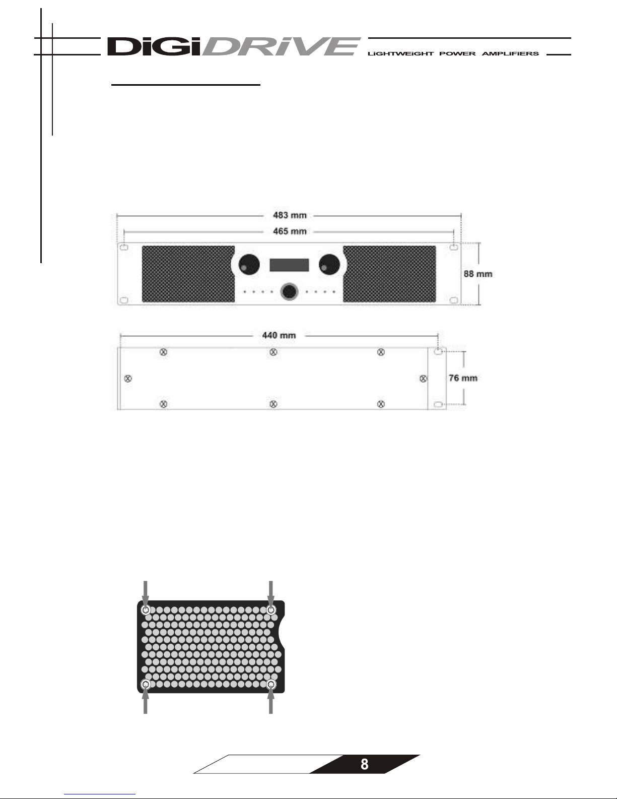
Use four screws and washers when mounting the amplifier to the front rack rails. Rear
support is also provided. Always mount the amplifiers rear support points to a suitable rear
support rail.
Cooling
Under normal operation of the power amplifier, overheating should never be a problem. The
air is taken in from the front and out through the back. It is of course essential that while the
power amplifier is running air is able to circulate around it freely.
The efficiency of the cooling will depend on the immediate environment. If the amplifier is
installed in a case, the open area at the back of the case must be at least 140 cm². The area
should be in line with the cooling vents of the amplifier. If this can not be achieved a forced
ventilation system has to be used.
Please clean the dust filters on a regular
basis. For this process unscrew and
remove the filter covers and take off the
dust filters to clean or replace them.
Do not place wet or dump dust filters in the
unit.
Page 9
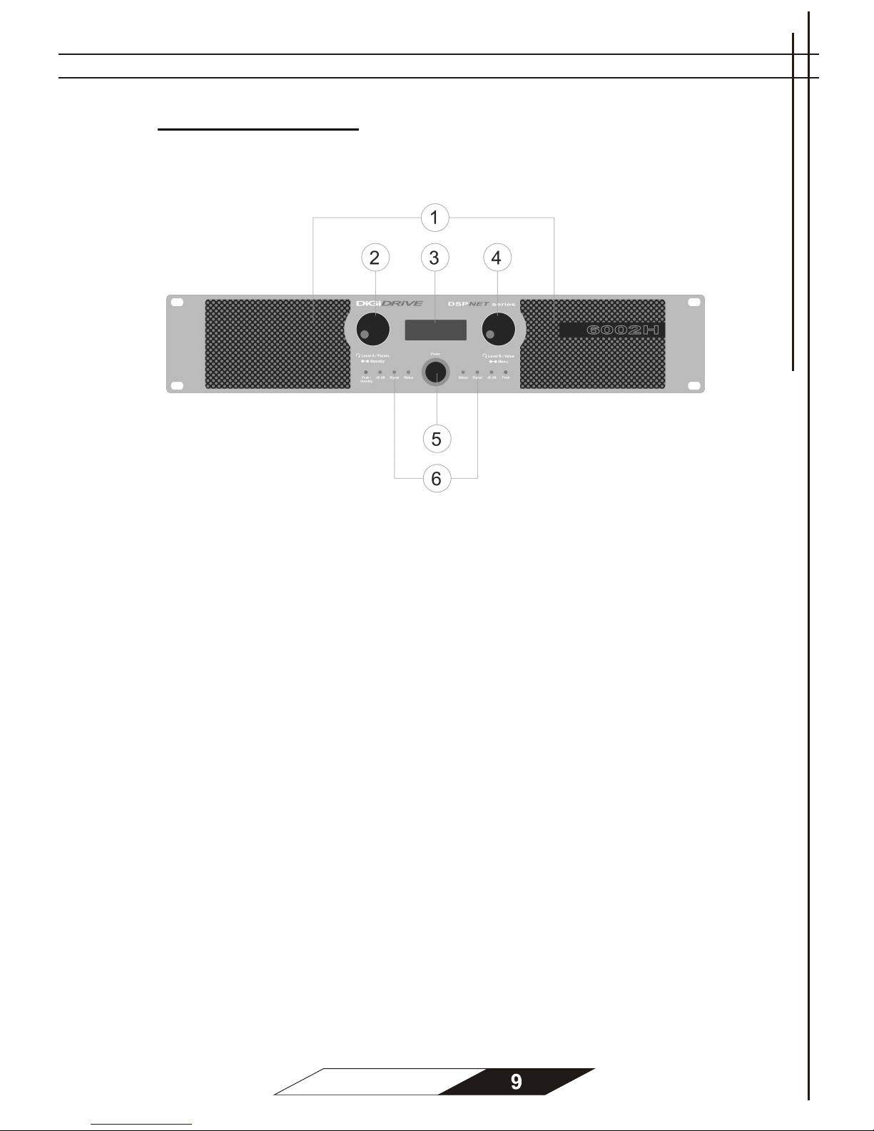
Operation Instructions
Front panel:
1. Dust filters
2. Volume control Level A / Parameter / Standby switch
3. LCD display
4. Volume control Level B / Value / Menu switch
5. Power switch
6. LED indicators
o Peak: Lights when the maximum output level is reached.
The left Peak LED also lights when the standby mode
is activated.
o -20 dB: Lights when the output level reaches -20 dB.
o Signal: Lights when the amplifier receives an input signal
(pre input gain).
o Status: Lights green when the amplifier operates normally.
Lights red when the amplifier is in protection state or a
fault condition exists.
Page 10
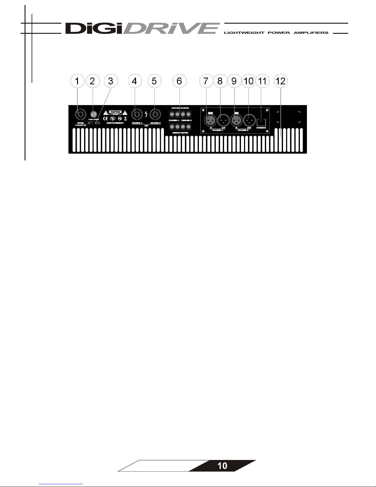
Rear panel:
1. Power cable connector
2. Fuse holder
3. Mains voltage switch
4. Speakon output channel A
5. Speakon output channel B
6. Contact output/input terminals
7. XLR input channel A
8. XLR loopthrough output channel A
9. XLR input channel B
10. XLR loopthrough output channel B
11. Ethernet connector
12. Cooling vents
The DSPNET series are rugged light weight amplifiers with a maximum output power of:
DSPNET4002H 2000 W per channel / stereo 2 Ohm
1200 W per channel / stereo 4 Ohm
650 W per channel / stereo 8 Ohm
4000 W per channel / bridge mode 4 Ohm
2400 W per channel / bridge mode 8 Ohm
DSPNET6002H 3000 W per channel / stereo 2 Ohm
1800 W per channel / stereo 4 Ohm
1000 W per channel / stereo 8 Ohm
6000 W per channel / bridge mode 4 Ohm
3600 W per channel / bridge mode 8 Ohm
DSPNET6002D 3000 W per channel / stereo 2 Ohm
2000 W per channel / stereo 4 Ohm
1100 W per channel / stereo 8 Ohm
DSPNET8002D 4000 W per channel / stereo 2 Ohm
2500 W per channel / stereo 4 Ohm
1400 W per channel / stereo 8 Ohm
Page 11
Features:
o Output power ranging from 2000 W to 4000 W per channel
o Built-in DSP:
- 4 PEQ bands and Hi/Lo shelving per chan nel
- Up to 24dB/octave crossovers
- Up to 2 seconds of delay
- Output limiter
- Full remote configuration via standard Ethernet interface
o Only 13 kg weight
o Dual Power Supply
o Class H or class D output stage technology
o Temperature-dependent, 4-fan cooling system
o 2 rack units high housing
o Full EN-60849 compliant supervision
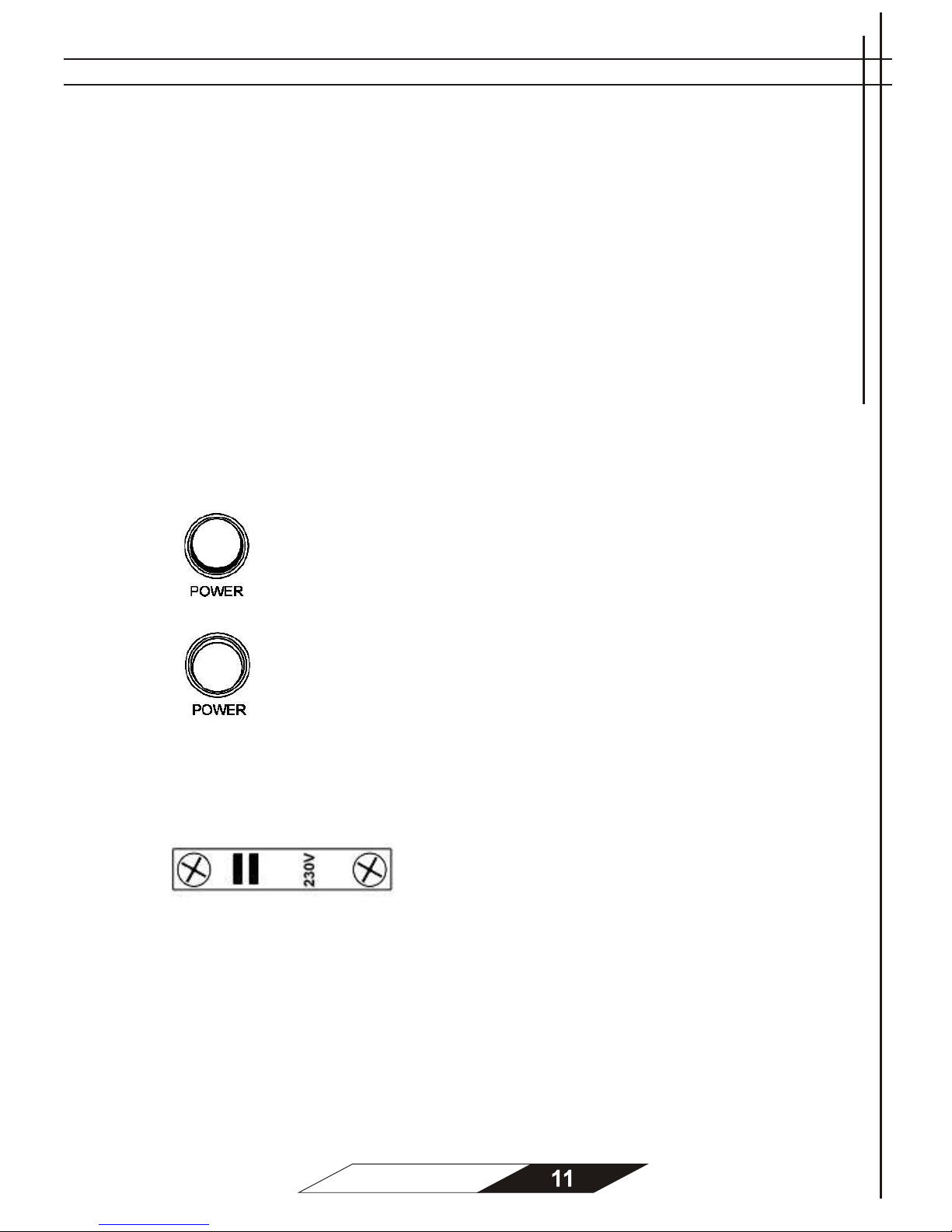
Power switch
The Power switch is a rocker-type switch. To turn the
amplifier on, push the top of the switch.
To turn the amplifier off, push the buttom of the switch.
Mains Voltage switch
You can choose between 110V or 230V mains voltage.
Do not change these settings when the amplifier is
switched ON.
Make sure you connect th e amplifier to the correct AC
line voltage. Connecting to the wrong line voltage is
dangerous and may damage the amplifier.
Page 12
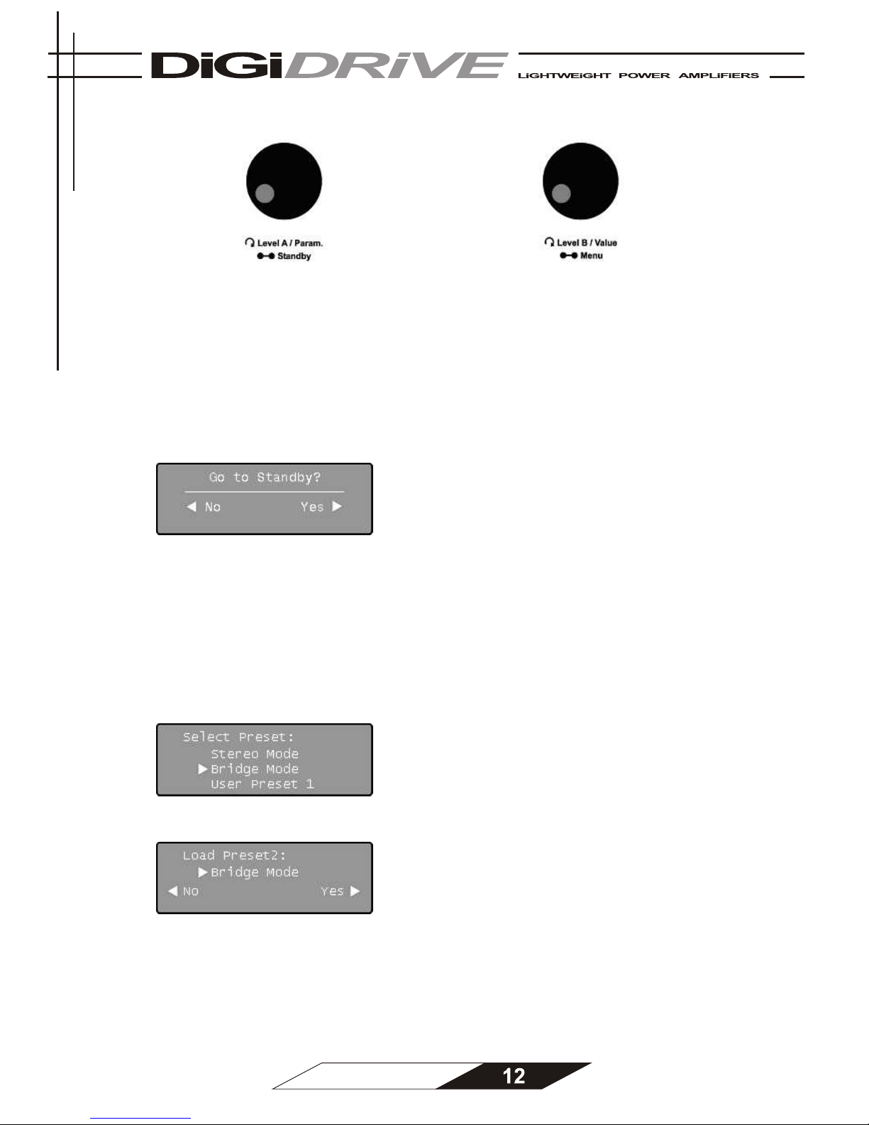
Channel A / Channel B controller
Spin the left controller to control the input
gain level of channel A.
Spin the right controller to control the input
gain level of channel B.
If one channel is muted (see “Software” on page 17) increase that channels input gain to
unmute the channel.
Standby
To set the amplifier to standby mode, press
and hold the left controller for more than 3
seconds. Now the LCD screen displays “Go
to Standby?”. Press the right controller to
confirm, or the left controller to abort.
Presets
To enter the Preset menu press and hold the right controller for more than 3 seconds. Select
a preset by spinning this controller.
The amplifier features 13 presets:
• 0 = last used settings
• 1 = stereo mode
• 2 = bridge mode
• 3 = user preset 1
• 4 = user preset 2
• 5 = user preset 3
• 6 = user preset 4
• 7 = user preset 5
• 8 = user preset 6
• 9 = user preset 7
• 10 = user preset 8
• 11 = user preset 9
• 12 = user preset 10
Press the right controller to select the preset of your choice. To confirm press the right
controller again or press the left controller to abort.
In the DSPNET network software you can select which preset is used at start-up.
Page 13
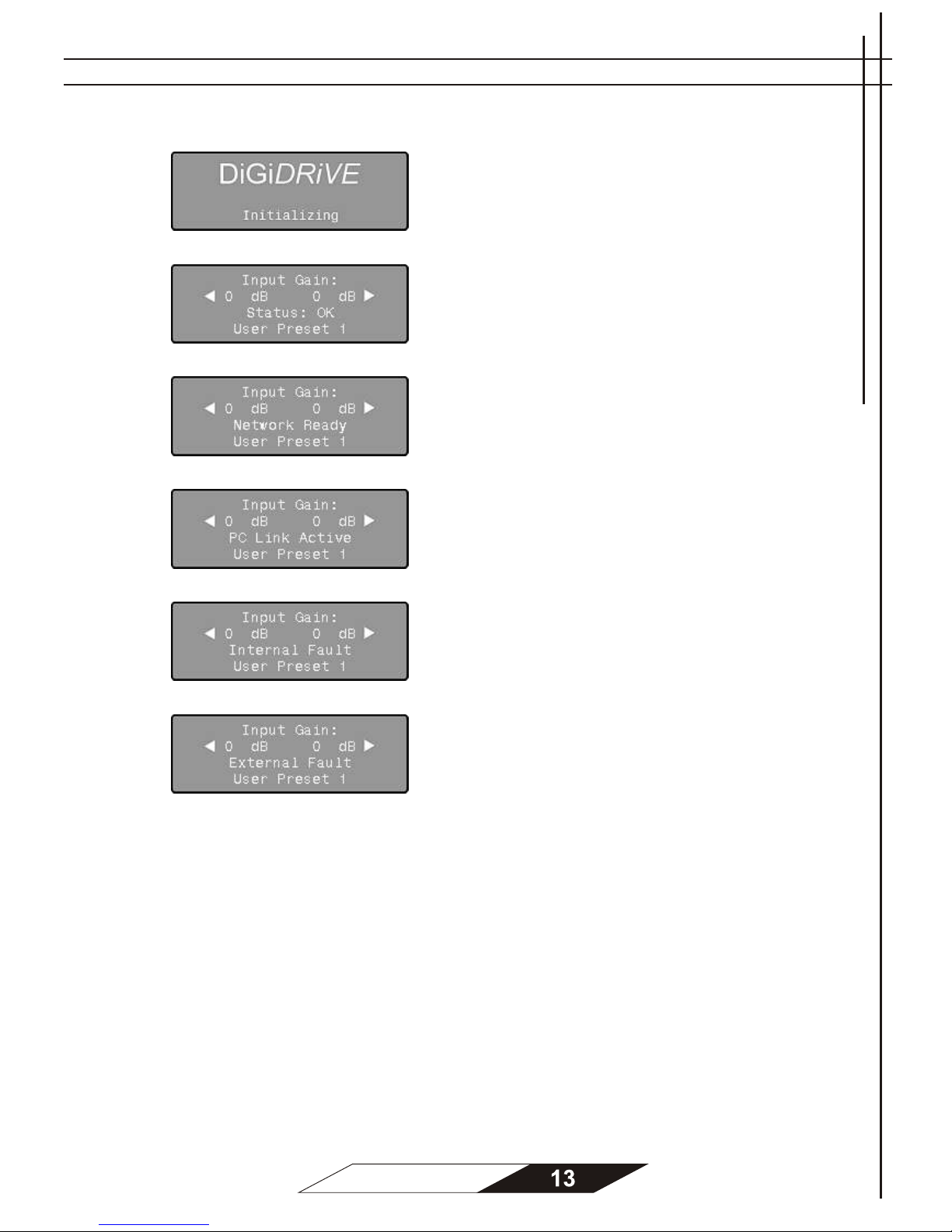
LCD Control Display
When you turn on the amplifier the LCD
screen displays “Initializing”. This process
may take a few seconds.
When the initialization process is finished
your amplifier is ready for operation. The LCD
screen displays “Status: OK”.
If the amplifier is connected to your network
via the Ethernet connector and has received
an IP address from the DHCP server (router)
the LCD screen displays “Network Ready”.
If the amplifier is connected to the DSPNET
network software the LCD screen displays
“PC Link Active”.
When a fault condition in the internal
functionality exists the LCD screen displays
“Internal Fault.
When a fault condition in the external
supervision exists the LCD screen displays
“External Fault.
Page 14
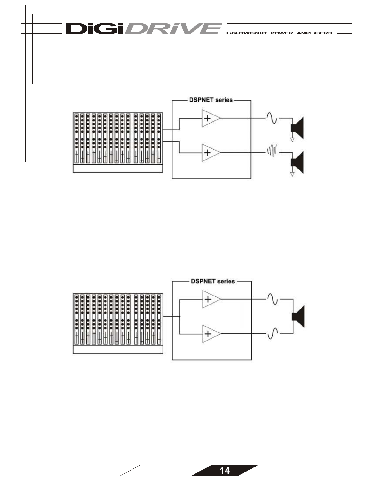
Operating mode
1. Stereo operation
Two fully independent amplifier channels (for normal operating mode).
Select preset “Stereo mode“ to enable normal stereo operation (see “Presets” on page 12).
2. Mono bridge operation
One-channel mono bridged operation. The output voltage is doubled w.r.t. the nominal output
voltage. The input signal is taken from channel A input.
Connect the + of your loudspeaker to pin 1+ of channel A output, and the - of your
loudspeaker to pin 2+ of channel A output.
Select preset “Bridge mode“ to enable mono bridge operation (see “Presets” on page 12).
Page 15
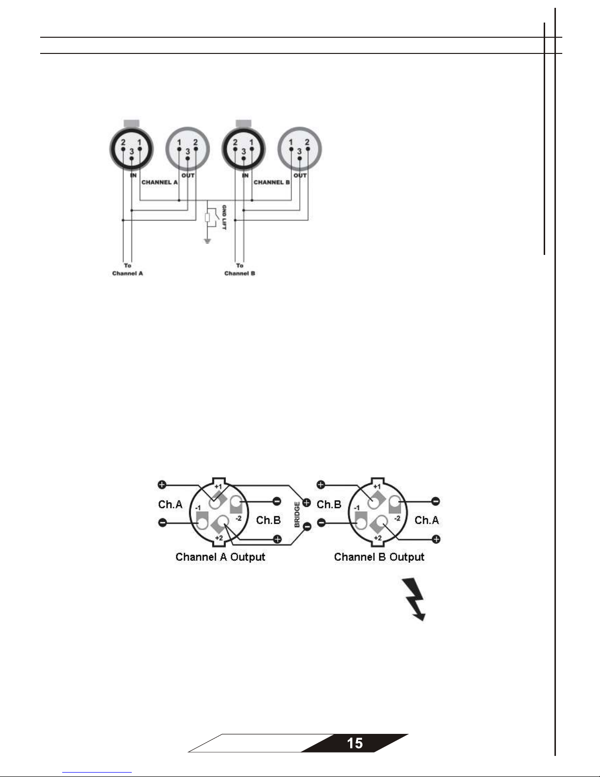
Wiring
XLR connection
Pin 1 : Ground
Pin 2 : Hot (in phase)
Pin 3 : Cold (out of phase)
Always use symmetrical (balanced)
shielded cable to connect the amplifier.
The Ground Lift and Input Sensitivity
can be enabled via the DSPNET
network software (see “Software” on
page 17).
Speakon connection
Both Speakon connectors are connected to channel A and channel B outp uts.
Channel A Output: Pin 1 + Channel 1 speaker signal
Pin 1 - Channel 1 speaker ground
Pin 2 + Channel 2 speaker signal
Pin 2 - Channel 2 speaker ground
Channel B Output: Pin 1 + Channel 2 speaker signal
Pin 1 - Channel 2 speaker ground
Pin 2 + Channel 1 speaker signal
Pin 2 - Channel 1 speaker ground
WARNING: Speakon terminals marked with the lightning flash
carry hazardous voltages. To prevent electrical shock, do not
operate the amplifier with any of the conductor portion of the
speaker wire exposed.
Speaker cabling
Larger wire sizes and shorter lengths minimize both loss of power and degradation
of damping factor. Do not place speaker cables next to input wiring.
Page 16
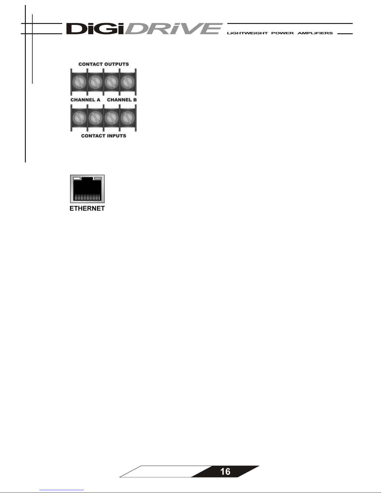
Contact output/input terminals
If the amplifier is switched off the output controls
are always open. If you switch the amplifier on they
are controlled by superv ision (see “Superv ision” on
page 16). The contacts are rated 2 4V / 1 Ampere.
With the contact inputs, it is possible to control
various amplifier functions such as mute or external
fault. Please refer t o the help file in the D SPNET
software for more information.
Et hernet connector
The Ethernet connector accepts an RJ-45 connector for
networking.
Built into the c onnector is a yellow and a green indic ator. T he
green indicator is lit when the amplifier is connect ed to your
network. The yello w in dicator shows an y net work activities.
To connect the amplifier with your network, use a standard Ethernet c able. You can c onnect
as many amplifiers as you want. You c an also use as many switches as you need but make
sure there’s only one router built in your local network. A switch is responsible for the data
transfer between all connected units of your network. A router with DHCP is needed to assign
the IP addresses to the units.
To connect your amplifier to a PC directly, follow t hese st eps:
§ U se a s tandard cros s-over c able to connec t the Ethernet port of the amplifier t o the
Ethernet port of your PC.
§ M ake sure your PC is not c onnected to another network at the same time (e.g.
disable wireless connections)
§ Go to Network Settings, right- click your LAN connection and click "Properties"
§ Selec t TCP/IP, and click "Properties"
§ C lick "Use the following IP address:"
§ Type in the field "I P Address": 192.16 8.0.1
§ Type in the field "Subnet mask": 255.255.255.0
§ Click "OK" and then "Close".
Page 17
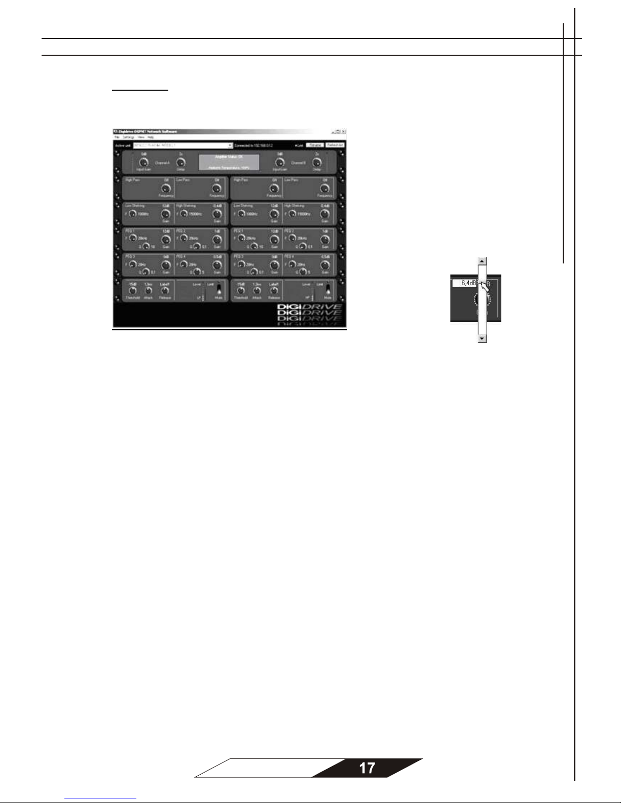
Software
User Interface
The DSPNET network software
was designed for the needs of
modern sound engineers.
The user interface shows the DSP
functionality lust like analogue 19
inch units. No irritating graphics,
just 1-to-1-portrays of every single
loudspeaker, am plifier and control,
be it a limiter, filter or parametric
equalizer.
To change a ll your
settings you have
to click the control
button of your
choice and move
the slider up or
down.
Y ou can change settings for:
INPU T
§ Gain -60dB – 0 d B
§ Delay 0 – 2 sec.
CROSSOVER
§ High Pass Frequency 20 Hz – 20 k H z
§ Low Pass Frequency 20 Hz – 20 k H z
SHELVING EQ
§ Low Shelving Frequency 80 – 1000Hz
§ Low Shelving Gain -12 dB – 12 dB
§ High Shelving Frequency 50 Hz – 15000 Hz
§ High Shelving Gain -12 dB – 12 dB
PARAME TRIC E Q
§ Frequency 20 Hz – 20 k H z
§ Q-Factor 0 – 10
§ Gain -12 – 12 dB
L IMITER
§ Threshold -31.75 dB – 0 dB
§ Attack 1 m sec. – 16.3 msec.
§ Release 20 msec. – 2.5 sec.
To mute the signal of one channel you have to click the mute s w itch. If one channel is muted
the LED lights red.
To learn more about the DSPNET network software please read the HELP file by
cli ck ing he lp- user menu .
Page 18
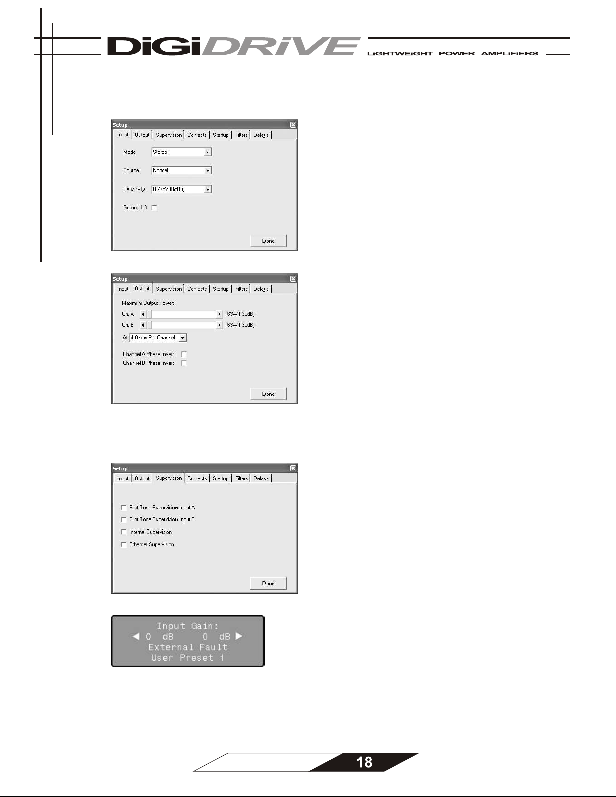
A m plif ie r s e t up
Input settings
§ In the Mode dropdown menu you can choose
between Stereo mode or Bridge Mono mode.
§ Open the Source dropdown menu t o choose
between normal and inverted source.
§ To adjust the sensitivity settings open the
dropdown menu and choose between
0.775V, 1V, 1.4V or 2V.
§ If you are getting a ground loop hum you
have to lift ground. Check the Ground Lift
checkbox to disconnect the ground
connection.
Output settings
§ Move the slider to set the value of the
maximum output power. In the dropdown
menu you can choose between 2, 4 or 8
Ohms per channel.
§ C heck the checkbox if you like to invert the
output phase of one channel.
§
Sup ervision settings
This amplifier features supervision to enable your installation to comply with international
emergency standards (such as EN60849). In addition, you can use these features to monitor
your amplifiers remotely wit hout using a PC.
Check the respective checkboxes in the
DSPNET network software to enable
supervision for:
• P ilot Tone S upe rv ision Input A / B
which monitors the presence of a pilot tone for
each channel (default OFF)
• Internal Sup ervision
which monitors the internal functionality of the
amplifier (default OFF)
• Ethernet Supervision.
which monitors the ethernet connection
(default OFF)
When a fault condition exists:
• LCD s creen display s “Ext ernal Fault”
• Status LED for the faulty channel light s red
• The output c ontact for the f aulty
channel will be open
Page 19
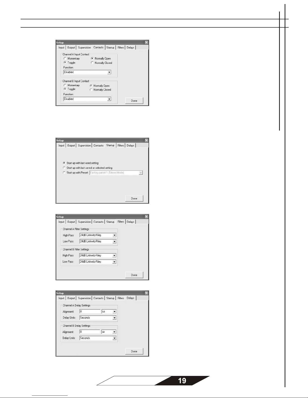
Contacts settings
§ If the "Momentary" radio button is checked,
close the contact (connect both terminals
with each other) to activate the selected
function. To de-activate the selected
function, open the contac t.
§ If the "Toggle" radio button is checked, close
and open the contact once to ac ti vate t he
selected function. Close and open the
contact again to de-activate the selected
function.
§ If the "Normally Open" radio button is
checked the selected funct ion is ac tivated
when the contact is closed.
§ If the "Normally Closed" radio button is
checked the selected function is activated
when the contact is opened.
St a r tup settings
§ Check a radio button to let the unit know if
you like to start up with:
o Last used setting
o Last saved and selected setting
o Your chosen preset
Filter settings
Choose the type of filter for the crossovers.
The following filters are supported:
- 6dB Butterworth (1st order)
- 12dB Butterworth (2nd order)
- 18dB Butterworth (3rd order)
- 24dB Butterworth (4th order)
- 12dB Linkwitz-Riley (2nd order)
- 24dB Linkwitz-Riley (4th order)
Delay settings
Alignment
To align m ultip le loudspeakers ( e.g. when steering a
2-way active loudspeaker or a line ar ray), choose t he
ali gnment delay h ere. First select the u nit
(m icrosecon ds, millisecond s or millim et ers) , the n
enter the value and press Ent er.
Delay un its
Set the delay units that are displayed in the main
window here.
Page 20

Troubleshooting
1. Problem: no sound
Indication: Status LED not lights
- Check AC plug.
- Make sure the amplifier is switched o n.
- Check mains fuse.
Indication: Status LED lights, -20dB LED not lights , Signal LED not lights
- Make sure the signal source is operating and try another cable.
Indication: Status LED light s, -20dB LED not lights, Signal LED lights
- Check position of Volume pots.
Indication: Status LED light s, Signal LED and -20dB LED responding to signal level
- Check the speaker wiring for bre aks.
- Try another speaker cable.
2. Problem: no channel s eperat ion
- Make s ure ot her equipment in the signal path such as mixers and preamps are s et for
stereo not mono.
- Make sure the amplifier is set to stereo operation. (see “Presets” on page 12)
3. Problem: distorted sound
Indication: Status LED lights, Signal LED responding to signal level, Peak LED not lights
- A f aulty s peaker or loose connection could cause this. Try another speaker and check
the wiring.
- The signal s ource might be clipping. Keep the input gain at least at -10 dB so that the
source does not have to be overdriven.
4. Problem: Hiss
- Unplug the am plif ier input to confirm that the hiss is com ing from the s ource or from a
devic e upstream. Erratic or popping noises indic at e an electronic fault in the offending
unit.
- Keep the noise floor low, operate the primary signal source at full level without
clipping.
- A void boosting the signal furth er between the source and the amplifier.
5. Problem: Squeals and F eedbac ks
- Microphone f eedback s hould be controlled with m ixer controls. If noise continues to
bui ld with no microphone gain, there’s a s erious fault in the signal processors or
cables. Work in s uccession f rom t he s ignal s ource t owards t he am plifier and check
each device in the signal path by reducing it s gain or by unplugging it.
Page 21
6. Problem: no connection between the amplifier and the DSPNET network software
- Check AC plug and make sure the amplifier is switched on.
- Make sure the amplifier is connected to your network
(LCD screen displays “Network ready”).
If not:
1. check the Ethernet wiring for breaks and make sure you are using standard
Ethernet cables (no crossover cables).
2. Make sure you are using a router which features DHCP to connect your PC
to your network.
3. Check if the green indicator of the Ethernet connector is lit. If not the Ethernet
link might be broken.
- Make sure you have chosen the correct Active Unit in the dropdown menu. Also click
“View” in the menu bar and than “List” to show all connected units on the right side
of the user interface. In this list all connected units will light green (OK) or red (fault).
All disconnected units light yellow.
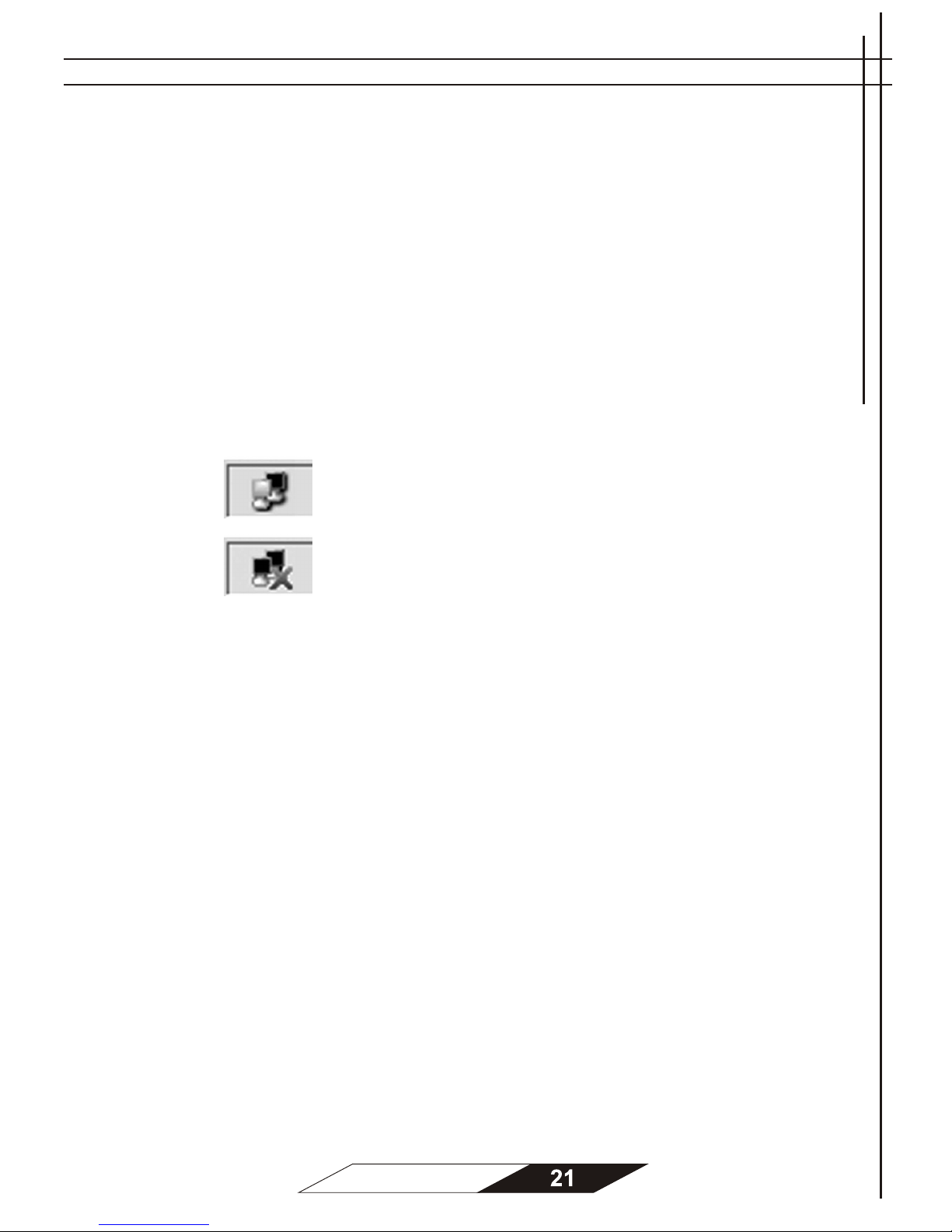
- Check the right side of your task bar to see if your PC has a local area connection:
connected
disconnected
- Check your firewall configurations. The DSPNET network software must be allowed to
access the network.
If the problems persists please contact your nearest DIGIDRIVE dealer.
Page 22
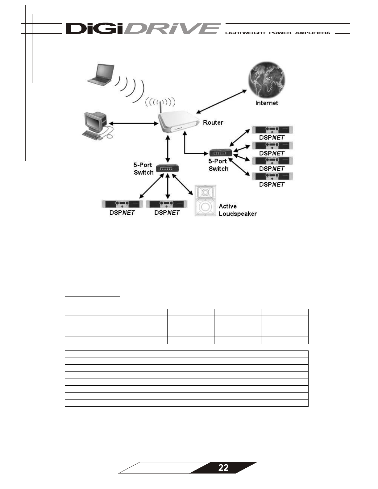
Standard Ethernet-based network
Notice: Only one PC at a time can control a unit. While a unit is connected to a PC, all other
PCs can only monitor the unit.
Specifications
Model
DSPNET4002H DSPNET6002H DSPNET6002D DSPNET8002D
Output Power
(RMS)
Stereo 2 Ohm 2000 W 3000 W 3000 W 4000 W
Stereo 4 Ohm 1200 W 1800 W 2000 W 2500 W
Stereo 8 Ohm 650 W 1000 W 1100 W 1400 W
Bridge 4 Ohm 4000 W 6000 W N.A. N.A.
Bridge 8 Ohm 2400 W 3600 W N.A. N.A.
S/N Ratio >100 dB flat, >103 dBA
THD20Hz..20kHz <0.1%
THD 1kHz <0.05%
IMD (SMPTE) <0.1%
Frequency Range 5Hz..40kHz
Damping Factor >600 (balanced damping factor)
Weight 13 kg
Dimensions 483 x 88 x 455 mm
Page 23

WARRANTY
Digidrive always strives for the best possible product quality and the best possible support.
Should a product not perform within its specifications, Digidrive will do its best to solve the
problem to your satisfaction.
Digidrive warrants that the product will be free from defects in materials or workmanship, as
long as the product is used under normal circumstances and properly maintained, for a period
of two years from the original date of purchase. This period can be extended to 3 years under
the conditions of the Extended Warranty Program.
During the warranty period, Digidrive or one of its authorized service partners will either repair
or replace the damaged unit at no charge for parts or labour to the owner. The choice to
either repair the unit or to replace it with another unit of the same type or, if this type of unit is
no longer in production, a unit with the same specifications, is entirely to the discretion of
Digidrive.
EXTENDED WARRANTY PROGRAM
The standard Limited Warranty will be extended to a 3 Year Full Warranty if the customer has
registered the product correctly within 1 month of purchase.
TRANSFERABILITY
The above warranties are transferable to subsequent owners as long as all the conditions are
met under the Optional Extended Warranty Program.
CONDITIONS
The warranty is not valid if the unit was originally purchased from an unauthorized seller, the
unit shows obvious external damage, the unit was damaged as a result of excessive
mechanical stress, the unit was misused or abused, the "Warranty Void If Damaged" seal is
broken, the serial number is removed or unreadable, the unit was used with an incorrect AC
voltage or the unit was connected to faulty equipment or the original bill of sale can not be
presented or shows evidence of alteration, erasing or forgery.
The warranty does not cover damage as a result of normal wear and tear or neglect.
To claim warranty, the customer must request an RMA code at Digidrive or one of its
authorized service partners and send the unit in by prepaid freight, including a copy of the
original bill of sale and a note (size Letter or A4) describing the problem, stating the Digidrive
RMA code, and full name, address (no PO box), telephone number and (if applicable) email
address. The unit will be returned freight collect.
Digidrive shall not be held liable for incidental or consequential damages of any kind arising
from the sale or use of its products.
Page 24

Spengler Str. 6
59067 Hamm
Germany
Phone: +49 - 2381 - 3730633
Fax: +49 - 2381 - 3730634
Email: [email protected]
www.digidrive.com
 Loading...