

Digidoor Paratrak Installation Instructions Manual
A Unique Concept in Roll-up Door Automation
Intended Use
The Paratra k is intended for the automat ion of the Digi Roll-up Door,
and may be adapte d to other makes of ro ll-up door s by means of
Adapter Kit s. Typically, a roll-up door w eighs about 30 kg.
The width of a rol l-up door may var y from 2,44 m to 3 m, and the height
from 2,135 m to 3 m.
Longer Driv e Shafts an d Chain Kits a re available for w ider and/or
higher doors.
If needed, (e.g. to avoi d a tow-bar on a vehicle in a shor t garage) the
Paratrak may be m ounted off-centre. Thi s is possible, and the longer
Drive Shaf ts are required.
Paratrak Installation Instructions on Digi Roll-up Doors
Preparation
Prior to automat ing the roll-u p door, inspect the door wit h a view to
ensuring satisfactory manual operation; it is a mistake to imag ine that
automation will overcome the faults of a mal-functioning door.
The operator will interpret excessive resistance to door movement,
due to poor alig nment, balanc e, snagging or exce ssive wear an d
tear of working s urface s as an obstac le thereby prev enting reliabl e
movement of the d oor. Eliminate all hin drances to fr ee and smooth
door operation.
Check that th e side-guides are fr ee of grease, dirt and den ts; and are
secure, ver tical and straigh t.
Check that th e triangular s upport br ackets are se cure and level. T he
springs ins ide the door roll shou ld have a light coating of grea se.
The door shou ld operate sm oothly and eas ily using one han d, and
remain stati onary whe n left at any poi nt of travel. Adju st the spri ng
force if neces sary (refer to the do or installation in structions).
Remove or d isable any unn ecessar y equipment o r fi ttings, not ne eded
for automated o peration. If fi tted, leave the centre lo ck un-locked.
WARNING!
Important Safety Instructions. Follow al l instruc tions care fully, as
incorrec t installation coul d lead to severe injury. It is im portant for the
safety of pe rsons to follow all instr uctions. Save these in structions for
future reference.
•
Do not allow child ren to play with door con trols
•
Automated doo rs should only be ope rated whilst in full v iew
•
Take care when operating th e manual release since an open d oor
may fall rapidl y due to weak or broken spr ings, or mal-adjus tment
•
Freque ntly examine t he installa tion for signs of w ear or damage,
in particular, that tracks and mountings are secure, and that the
balance of the s prings is correc tly adjusted
•
For use of th e manual release, re fer to the secti on Manual Opera tion
on page 11
•
During mainte nance or adjustme nt, disconnect t he mains supply
•
This a ppliance is not i ntended for us e by persons ( including
children) wit h reduced phys ical, sensor y or mental capabilitie s, or
lack of exper ience and know ledge, unles s they have been g iven
supervi sion or inst ruction co ncerning us e of the applian ce by a
person res ponsible for their sa fety.
Permanently fi x labels warning agai nst entrapment in a p rominent
place or near any fi xed controls.
After ins tallation, ensure that t he mechanism is prope rly adjusted and
reverses wh en closing upo n an obstacl e, 40mm high, pl aced on the
fl oor.
The drive mus t not be used on a roll-up door in corporat ing a wicket
door (unles s the roll-up door cann ot be operated if the wick et door is
closed ).
After ins tallation, en sure that par ts of the door d o not extend ove r
public foot pat hs or roads.
Contents of the Package
The Paratra k Operator co nsists of a c arton and a se t of two shaf ts,
which may be cho sen for standard or s pecial door width s.
The carton c ontains:
Recommended Tools and Equipment for this installation
•
An Instruction pamphlet
•
The Paratra k Drive Unit
•
Battery B ox assembly,
with a Control ler and two
12V Batteries
•
Hardwar e Pack with nuts an d bolts
•
24V Power Adapter
•
Two Sprocket assemblies
•
Four Bearing Br ackets
•
Grease Sachet
•
Junction Box
•
Curly Cable
•
Two lengths of roller-chain
•
eKey Remote
•
Battery c able with plug
•
White Jumper w ire
•
500 mm of twin-fl ex
• Electric D rill (with hammer ac tion)
• Drill Bits
Masonry: 5.5 mm, 8 mm
Steel: 3.5 m m, 4 mm, 6 mm, 7 mm
• Tape Measure – 5 m
• Hammer
• Hacksaw
• File
• Allen Key 3 mm
• Scr ewdriver
6 mm (Philips/Pozi)
• Spanners
Sockets: 10 mm
Flat/Ring: 7 m m
• Spirit Level
• Step Ladder – 1,7 to 2 m high
• Extensio n Lead to suit
– INSTALLATI ON –
It is assumed th at the proper conditio n and
balance of the d oor has been achieved.
Step 1
Insertin g the chains into the Spr ocket Covers, lef t and right
Insert the fi rst link (the o ne withou t
the anchor pin) o f one of the chain
bundles into t he opening of th e
shorter si de of a Sprocket C over
assembly. Pus h the chain thro ugh,
link-by-link , until it emerg es at the
other side. Pull t he chain abou t
halfway th rough the ass embly.
Repeat for the ot her chain bun dle
and Sprocket C over assemb ly. See
Figu re 1.
Step 2
Fixing the C hain Anchor to the fl oor, left and righ t
Starting on t he left side, mark out the d rilling dimensions as in F igure 2.
Using a Ø8 mm masonry bit, dri ll each hole as indicated to a de pth of at
least 65 mm, and fi t two Ø8 x63 Screw Plugs. Please refer to the following
tips. Note: t he box has a drilling temp late for ease of use.
TIPS
1. Ac curacy is i mportan t! Before drillin g, extend the c entre-lin es well
beyond the hole-positions.
2. Start eac h hole with the d rill set to norma l (no hammer) and, w hile
focusing on ac curacy, dril l initially to a de pth of about 5m m before
changing the d rill to hammer.
3. To avoid snap ping screws inser ted in the fl oor; after drilli ng each hole,
leave the mound s of dust. Insert the t ips of the screw-plugs pa rt-way
into the holes, a nd then brus h away the moun ds of dust. Dr ive the
plugs in fl ush. Apply a lick of greas e to the bolt threads b efore fi tt ing.
Figure 1
Figure 2 Left Si de. Mirror for the Rig ht side.
Step 6
Connecting the Cables
Flex the side cli ps and remove the Li ght Cover from the f ront of the Batte ry
Box. Set the cove r aside until later.
Place the two b atteries in the Bat tery Box with the term inals of each near
the middle.
As in Figure 8, co nnect the Black batter y wire to the left Black ter minal,
and the Red bat tery wire to the right Red ter minal. Leave the 3-Pin plug
from the bat teries un-plugged at th is stage. Connect the W hite Jumper
wire from the le ft Red termin al to the right Bla ck terminal. In sert the
matching plugs fro m the Par atrak into the so ckets, fi rst and fourth f rom
the right of the C ontroller. See Figure 9.
At this stage, c heck that the do or is neutrally b alanced. If nece ssary, adjus t
the spring fo rce to balance the door.
Step 7
Cutting the Shafts to length
Starting on t he left side, move the Sp rocket Cover assembly to t he same
level as the bot tom rail. Note the size of the gap be tween the Sprocket
Cover and the sid e guide (see Figure 10). In sert the formed e nd of a Shaft
into the hub of th e sprocket ins ide the Sproc ket Cover Ass embly and,
while maintai ning the gap, hold the Shaft h orizontally so that it overl aps
the hub of the Par atrak, and ma rk the Shaf t opposite th e centre of the
nearest hub s crew (see Figure 11).
Cut t he Shaf t at th at mar k and de -bur r the sh arp ed ge wit h a fi le . Slide two
Bearing Brac kets onto the shaf t, clip them int o the bottom rail (a s in Figure
12) and push the end of t he shaft into the Ou tput Shaft.
Figure 3
Step 3
Securing the Chain to the triangular support bracket
Again, star ting on the lef t side, mark the drilling posi tion on the upp er
fl ange of the triangular support brac ket as in Figure 4. Centre-punch and
drill a Ø4.5 mm hole.
Refer to Figure 5. N ear the top end of the chain, c hoose a chain link such
that, when an M4 S ocket Head Cap Screw i s pushed through tha t link and
through the Ø 4.5 mm hole in the tri angular suppor t bracket, a washe r and
an M4 Ny lok Nut c an be fi tte d, leavi ng suffi cient th read on t he bolt s o that
the chain may be te nsioned. For n ow, take up the slac k. Repeat for th e
right side.
Step 4
Mounting th e Paratrak and the Bat tery Box
With the foot of t he door
opened to wais t height,
measure and mark the
horizontal mi d-point of t he
door just ab ove the botto m
rail. Position th e Paratrak uni t
with its ou tput stage c entred
on the mid-p oint of the door,
and its unde rside touch ing
the aluminium b ottom rail.
Drill through the upper-right
mounting bus h with a Ø6 mm
bit.
Reach under th e bottom rail
and push an M6 Cup Square
Bolt through t he hole and the
mounting bush, and fi t an M6 nut, fi nger-tig ht. Now, with the Ø6 mm bit,
drill throug h the remaining three mo unting bushes. Remov e the unit from
the doo r and enla rge all the holes wi th a Ø7 mm bit. Refi t the unit u sing
four M6 Cup Squ are Bolts and M6 N uts, tighte ning them with a 10 mm
socket nut-d river until the head s are fl ush on the outside.
Step 5
Battery Box
Hold the Batt ery Box (witho ut
batteries) against the door
to the left of t he Paratrak
with its fee t standing on t he
bottom rail, w ith a 30 mm gap
betwee n the two.
In this positi on and on the
right of the box , drill through
the mounting b ush that best
suits the co rrugation o f the
door with a Ø6 mm bit. A s
above, fi t an M6 Cup Square Bolt and nut, fi nger-tight. Drill thro ugh the
correspon ding mounting bush on the lef t. Remove the Box and enlarge
the holes wit h a Ø7 mm bit. Secure t he Box with two M6 Cup S quare Bolts
and nuts, tig htening them with a 10 mm socket nut-driver u ntil the heads
are fl u sh on the outside.
Figure 4 Figure 5
Figure 6
Figure 7
Figure 8
Figure 9
Figure 10 Fig ur e 11
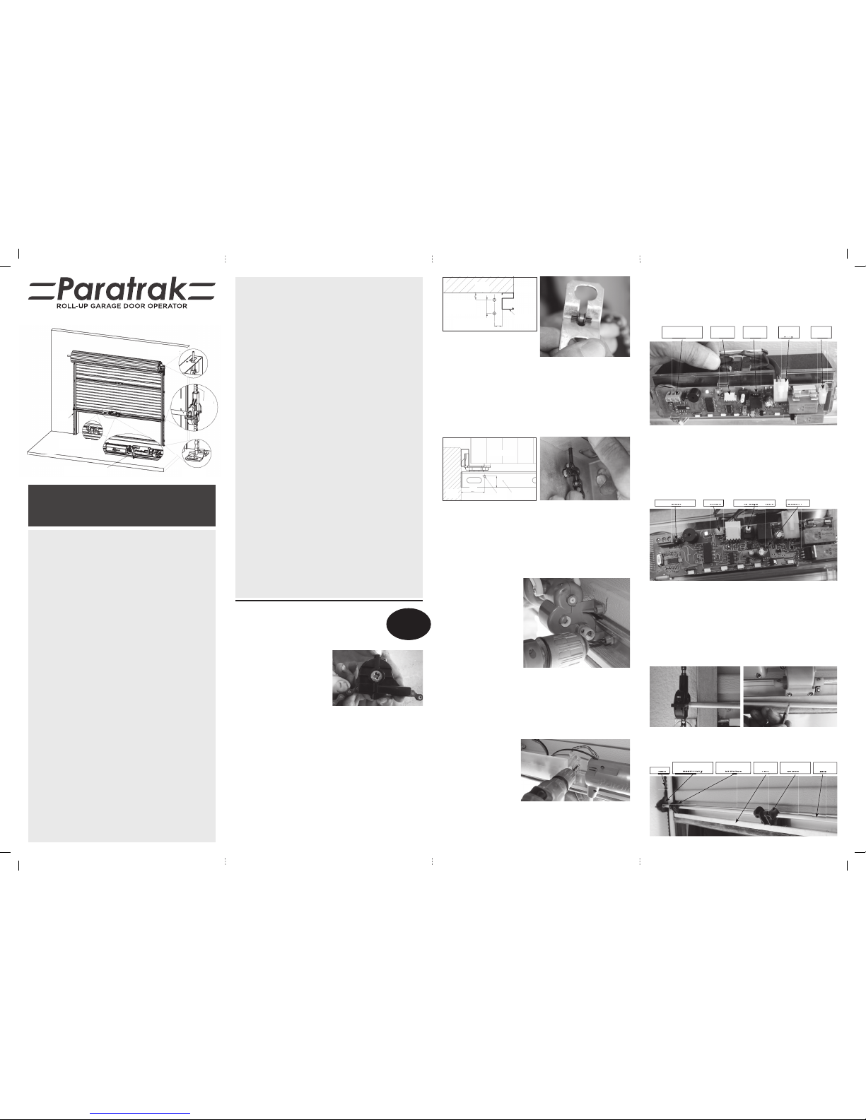
The Paratrak dr ives the door symme trically by
means of chain s and sprockets , applying the
force symmetr ically to bot h ends of the bott om
rail, ensuri ng smooth and even op eration.
Optional r eceiver
terminals
Controller
socket
Curly cord
socket
Battery
plug
Motor
socket
plug
Auto close l ink Button Force adjustment Beam link
Beam link
A video is
availabl e on our
website to as sist
you with thi s
installation.
As in Figure 3, e ngage the pin at the e nd of the chain in the ‘ V’ of the Chain
Anchor. Ensuri ng that the chain is b etween the wal l and the sprocket i n the
cover, place the C hain Anchor over t he screw plugs an d fi t two Ø6 Coach
Bolts with B ody Washers. At this stage, l eave the bolts loose enoug h to
allow the Chain A nchor to move (‘Float’ ) freely. Repeat for the ri ght side.
Figu re 12
Sprocket ho using
assembly
Chain
Outer bear ing
bracket
Bottom
rail
Inner bear ing
bracket
Left drive
shaft
bracket
rail
assembly
bracket
assembly
shaft
Front
Wall
Doorway
Left Hand
Track
Dimensio n ‘B’
may vary from
18-22m m
40
‘B’
Dimensio n ‘A’ may
vary from 22-25mm
‘A’
Roll-up Door
Top Vi ew
Triangular
Bracket
Ø4.5
23
48
Doorway
Front
Wall
Top Chain Fixing
and Tensioner
Chain
Left
Chain
Drive
Shaft
Sprocket
Housing
Chain Anchor
right side
Bearing Bracket
2 each side
Paratrak Unit
mounted to the d oor
S t ep 11
Set-up
Switch on the Powe r Pack at the 3-Pin Main s Socket.
Referring to Fig ure 9, plug the 3-Pin p lug from the bat teries into t he
socket, second from the right on the Controller. The lights wil l fl ash and
the beeper will sound, and the LED on the Controller will fl ash orange. (If
the LED shows g reen, a ‘Reset’ is requ ired; see Reset on page 11).
• Ensure that the Limi t Slide is in the u pper-most po sition. Refer to
Fig ure 17
• Move the Manual O ver-ride Lever fully a nti-clockwi se
• Press the but ton on the Controlle r and the LED will show red
• By hand, move the door to the closed po sition against th e fl oor
• Move the Manual O ver-ride Lever fully c lockwise
• Dep ress the Lim it Slide But ton and move the Li mit Slide slowl y
downwards , until the LED on the Co ntroller change s from red to green.
Release the Li mit Slide Button.
Keep clear dur ing this phase.
Press the but ton on the
Controller (see Figure 9).
The Paratra k will slowly open
the door in ‘seek ’ mode until
the fully ope n position is
reached. The Pa ratrack wil l
then close, s topping on the
fl oor.
The Controll er will beep
twice and th e LED will
double-fl ash orange.
St ep 12
Adding the eKey Remote
Pre ss the b utto n on the C ontro ller and the LED will fl as h oran ge. Wit hin 3 0
seconds, pre ss the chosen butto n on the eKey Remote, causing the L ED
to turn off. Pre ss the same button o n the eKey Remote again and t he LED
will fl ash and the Beeper will sound fou r times. The eKey Remote is ready
to use. Note: For sec urity reas ons, adding re motes require s the door to
be fully clos ed.
For addition al eKey Remotes, repeat Ste p 12.
Reset.
If, for any reason, the Se t-up procedure above nee ds to be repeated, fi rst
reset as follow s:
From the Contro ller, un-plug the Teleco m plug (Curly co rd) and the
Battery p lug. Push and hold the but ton on the Controller while i nserting
the Bat tery plug. T he Lights will fl as h and the Beeper will s ound and th e
LED will fl ash orange. C ontinue Set-up (Step 11).
St ep 13
Adjusting Obstacle Sensing
Importa nt (For safety reasons, p erform this check t wice a year.)
Referring to Fig ure 9, set the ‘FORCE’ adj uster mid- way. Using the eKey
Remote, open the d oor. Start the door clos ing and, while standi ng to the
left or righ t of the Paratrak, obst ruct the door by hand. Th e door should
sense the obs truct ion and reverse. I f the force seem s too high or low,
make a slight cha nge on the ‘FORCE’ adjuster (cl ock-wise for more), and
test again.
Step 8
Securing t he Shaft to the Motor
Important! With th e door open to slig htly above wai st level (for a
comforta ble working height ), check that the foot of t he door is level.
Move the Manual O ver-ride Lever a nti-cloc kwise and t urn the Out put
Shaft by hand u ntil the holes a re horizonta l, as in Figure 13. Re-e ngage
the motor by movin g the Manual Ove r-ride Lever cl ockwise to l ock the
Output Shaf t in place.
Important! Check that th e gap betwe en the Sprocke t Cover and the
side guide is c orrect (Fi gure 10). Using a sha rp Ø4 mm bit, carefully drill
through the ho le in the Output Sha ft with atten tion being paid to keepi ng
central, level a nd square. Push an M4x 20 Socket Head Cap Sc rew through
the hole just d rilled.
Repeat ‘Cut ting’ and ‘Securing the Sha ft’ for the right side (Ste ps 7 and
8), remembering to slide the two B earing Brackets ont o the other Shaft.
Release the moto r by means of
the Manual Ove r-ride Lever, lif t
the door until t he tips of the M4
screws come into view and fi t
M4 Nylok Nuts . Lower the door
until the Head s of the M4 screws
come into view. Tig hten the M4
screws and nu ts with a 7 mm
spanner and a 3 mm Allen key.
Step 9
Securing the Bearing Brackets
(For a D igi-Roll-up: If fi tte d, remove the red Foot Stop s from the bottom
Rail.)
On the left side, position the left edge of th e Bearing B racket fl ush wit h
the end of the alu minium Bottom Rail. Using a Ø3. 5 mm bit, dr ill through
the mounting bushes in the Bearing Bracket and fi t two #8x25 mm S elf
Tapping Screws. Li kewise, mount the next B earing Bracket 60 0 mm to t he
right of t he fi rs t. Repeat the a bove for mountin g the Bearing B rackets on
the right side. S nip a corner off of the gr ease sachet and apply g rease to
the shaft s where they are visib le in each bracket, as w ell as the undersid e.
Tensioning the Chains
Release the moto r by means of the Manual Ove r-ride Lever and, by hand,
close the doo r fully. Now tighte n the Ø6 mm C oach Bolts i n the Chain
Anchors, left and right.
Using a 3 mm Allen Key and a 7 mm spanner, tighten the M4 Nylo k Nut
above the tria ngular suppo rt bracke t, to tension the c hains so that n o
slack is evid ent and both chains fe els fi rm. Ref er to Figure 5.
St e p 10
Mounting th e Power Pack and Junction Box
Remove the dus t-cover from the Ju nction Box. De pending on the posi tion
of the nearest m ains 3-pin power socke t, choose a front or side wall . On
that wall, u sing the #4 screws and Ø 5.5 mm p lugs su pplied, mount th e
Junction Box as in Figure 14, 1.1 m from the fl oor and 100 mm from the side
guide of the do or.
Take care to avoid damagi ng the wires in the Junc tion Box.
Plug the Power Pack in to the 3-Pin Mains S ocket; do not switc h on yet. Use
the t win-fl ex cable to connect the Power Pack to the Junc tion Box as in
Figure 15, making u se of the Yellow and Blue terminals , marked ‘AC 24V’.
(Note: depend ing on the position of the pow er point, a longer length of
twi n-fl ex may be r equir ed). S ecur e the ca ble to t he wall by mean s of cab le-
saddles. Fi t the dust-cover to the Ju nction Box. Plug the sh ort end of the
curly cord int o the Junction Box.
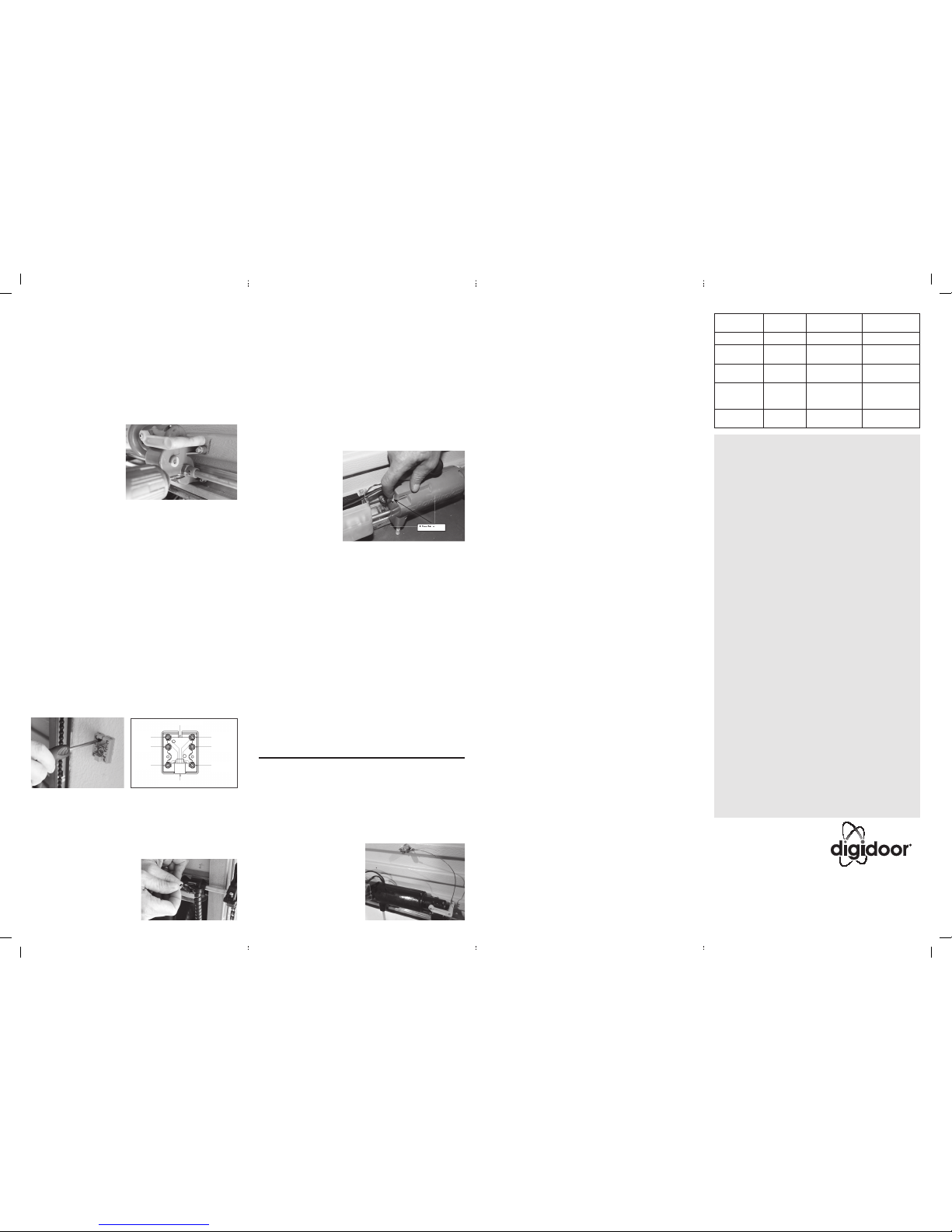
As in Figure 16, at tach the beginning of the s traight portion of the c urly
cord to the tip of th e nearest bearing
bracket wit h a cable-tie, t hen at the
diagonal at tachment po int. Plug the
free end of the c urly cord into th e
socket third f rom the right of th e
Controller (F igure 9). Secure the cord
to the next bear ing bracket w ith a
cable-tie. Finally, fold up any slack
cable and sec ure it with a ca ble-tie.
Trim the free ends of t he cable-ties.
Measure the di stance fro m the Key Release to t he end of the Manu al
Over-ride Lev er in the horizo ntal positio n. Cut the cabl e 150 mm l onger
than this dis tance. Insert the Key Re lease into the body and loc k it. Loop
the cable aro und the end of the Manu al Over-ride Lever an d secure it with
an electr ical screw clamp.
Manual Operation
To release the door fr om the Paratrak uni t for manual operati on, move the
yellow lever at th e right end of the unit, from i ts horizontal positi on in an
anti-cloc kwise direct ion until it touches t he body.
The door may now b e moved by hand. To re-engage th e drive, return the
yellow lever to the h orizontal position in a c lockwise direct ion. Note that
the door may be re -engaged in any positi on, and, if not closed, the nex t
operation w ill cause the door t o close slowly until t he fl oor is rea ched.
Fitting Safety Beams
Choose and mar k a suitable mounting heigh t on both sides of t he gate
or doorwa y, low enough to protect todd lers and pets, but not l ower than
the under-sid e of most motor ve hicles. Mou nt the Safety B eam units
(Transmitter and Receiver) opposing one another, and at the chosen
height. Note: Do no t screw or rivet t hrough the sid e tracks. T his will
interfere w ith the free movement o f the curtain.
Wiring (Refe r to Figure 15)
In the Junct ion Box (dust cover re moved), use the Wh ite terminal to sup ply
positive(+) voltag e to both beam units, a nd the black termina l to make the
negative (-) con nection to b oth beam unit s. If a Digitronic S afety Beam
set is used, in t he receiver uni t, connect a s hort wire f rom negative (-)
to ‘COM’. Lastly, connec t the Red terminal to the beam no rmally closed
(N.C.) terminal on th e beam Receiver unit.
Set-up
Referring to Fig ure 9, enable the Safety Bea m by removing the link below
the Telecom plug. The S afety Beam w ill not funct ion if this is no t done.
Interrupt ing the beam during closing w ill cause the Paratrak to s top and
reverse, but wi ll be ignored during op ening.
Enabling Auto-close
Warni ng! I t is stro ngly advised that Safety Beams are fi tted before
making use of Auto-close.
Referring to Fig ure 9, remove the Auto-cl ose Link to the right of t he 3-way
screw termin als. For conveni ence, store the L ink on a single pin . The
Auto-clo se timer will start af ter the door has stoppe d opening; after ten
seconds the be eper will sound and the lights will fl ash f or a f urther ten
seconds bef ore the door start s to close. Interrupt ing the safety beam wi ll
reset the time r, and the timer will not sta rt while the beam is in terrupted.
Fitting a Wall Console
Fix the Wall Cons ole to the wall, in a convenient po sition (usually next to
the side door) a t a height of at least 1,5 m, within sight of the automa ted
door, but clear of mov ing parts. To add the Wall Cons ole to the Paratrak,
close the doo r and un-clip the cover f rom the Battery Box. A s in ‘Adding
an eKey Remote’, press th e button on th e Controller a nd the LED will
fl as h. Wit hin 3 0 seco nds, press the l arge bu tton on th e Wall Consol e,
causing the L ED on the Controller to turn of f. Press the same button on
the Wal l Console and t he LED will fl ash a nd the Beeper w ill sound four
times. The Wall C onsole is ready for use. T he large button will c ontrol the
Paratrak (Op en, Close and Stop). The button w ith the light symbol tur ns
the Paratrak l ighting on and of f. (Note that this light ing will still go of f after
three minute s). Normal operation of th e Paratrak is locked and u n-locked
by means of the bu tton with th e key symbol. Th e LED on the Contro ller
changes fro m green to red when locked .
Fitting an Additional Receiver
An addition al receiver may be con nected by means o f the terminals sh own
in fi g ure 8. These are:
‘-’(0V), ‘+’(24V ) and ‘▲▼’ (O perate, N.O. conta ct, acti ve low signal). Thi s
receiver sho uld not exceed 50 mA. The ra nge of this rece iver may be
degraded; i f so, increase the mounting d istance to at least 1 met re from
the Controller.
Status Indications
The single L.E. D. on the controller indicat es the status of the Parat rak as
follows:
• Green (solid) - Ready, Mains is on
• Green (fl ashing) - Ready, Mains is off - b attery voltag e good
• Red (fl a shing) - Batter y low – door cannot oper ate – restore mains
to charge
• Red (solid) - Door locked by mea ns of the wall con sole – will
beep once when operation is attempted – unlock
using the wall console
• Orange (fl ashing) - R eset – Programming mode – see Step 11, Set-u p
for details Pag e 9
Note: To save power, the Status L. E.D turns off when th e Courtesy Light
times out.
– ADDITION AL INFOR MATION –
Erasing all e Key Remotes
Note: This proce dure will eras e all the eKey Remote s that have been
added to the Par atrak. Ens ure that all the rel evant eKey Remote s are
available, to re- add them af ter erasing. Re ferring to Fig ure 9, press and
hold the but ton on the Controller. After te n second s the LED wi ll fl ash
and the Beepe r will sound four time s. This indicates t hat all eKey Remotes
have been cleare d from memory.
Fitting a Key R elease
A Key Release is req uired where
there is no side d oor; the gar age
door providi ng the only access.
Refer to Figure 18. In t he second
externally recessed corrugation
above the Parat rak, mark a po int
250 mm to the left of th e Manual
Over-ride Lev er, and 150 mm above.
Drill and moun t the Key Release at
this mark .
Figur e 18
WARRANTY
Hydro Doors and Gate s (Pt y) Ltd (Hydro) warrants to the fi rst retail
purchaser of a D igidoor Parat rak Operator that the prod uct shall be
free of any defec ts in materials and/or workm anship for a per iod of
twelve months (One Year) from th e verifi able date of purchas e. Such
verifi cation will include a valid proof of p urchase by t he fi rst ret ail
purchaser, whic h shall includ e if possible t he serial numb er of the
motor under warranty.
Upon r eceipt of the pro duct, th e fi r st retail purchaser is under
obligation to c heck the produc t for any visible defe ct. This warran ty is
available on any D igidoor Operator so ld and installed in th e Republic
of South Afric a. For any Digidoor Operato r that is sold and installed
outside th e borders of the Re public of South Af rica, the obliga tions for
repairing thi s product under wa rranty will be born e by the distributor
of the product in the territory concerned. The terms and conditions of
warrantie s in each territor y outside th e Republic of Sout h Africa will be
available fro m the distributor i n that territory.
Conditions
The warrant y shall constitute the s ole remedy available unde r law to
the fi rst reta il purchaser f or any damages related to or resulting from
a defecti ve part and/or produc t. The warranty i s strictly limite d to the
repair or repla cement of the parts of t his product which are fo und to
be defective.
The warranty does not cover:
• Non-d efect dam age caused by u nreasonable u se (includi ng use
not in complete accordance with Digidoor installation and owners
instructions).
• L abour charg es for removal o r re-insta llation of a repai red or
replaced unit , transpor t costs incurred in get ting the prod uct to
Hydro. Hydro will q uote for in-situ war ranty repairs if re quested.
• Damage to the product c aused by ligh tning, power su rges, or
incorrect installation.
• Any Hydro garag e door operator us ed to automate more than on e
door at one time.
• Any H ydro garage d oor operato r used outdoo rs, includin g
carports.
• Any Hydro residential gar age door ope rator used in exc essive
traffi c applications for example: an apartment-block, parking
garage etc.
• A ny unauthorised non-Hydro modifi cations to the product or
components thereof.
• Consequen tial or incidental da mage to property o r person.
• Batterie s installed in the op erator, remote controls o r wall console.
Hydro will repai r, or at its option rep lace, any device, w hich is
determined to be defective in materials and/or workmanship at no
cost to the owner for the repair and/or replacement part. Defective
parts wil l be repaired or re placed with ne w or factor y rebuilt par ts
at Hydro’s option. Hyd ro shall not be lia ble for conseq uential or
incidental d amage to prope rty or pe rson. Warrant y repairs s hall
be effec ted, provided t hat the produc t is return ed to Hydro at the
owner’s expe nse. No represent ative or perso n is authorized to a ssume
for Hydro any othe r liability in con nection with t he sale of this produ ct.
Fig ure 17
Figu re 14 Figu re 15
Figu re 16
Limit slide
Choose reliability,
choose quality, choose
www.hydrodoors.co.zaE-mail: info@digidoor.co.za
Patented Design: 2015/07462
®
Registered Trademark © Digidoor 2017
Hydro Doors & Gates (Pty) Ltd.
8 Horsechestnut Ave nue, Northlands Business Park,
Northriding, Gauteng, S outh Africa.
Tel: 011 888 6969
Supply Voltage 240 V A.C.
Max. moto r
power
109 W
Mains Current 25 m A Motor Voltage 24 V DC
Power
consumption
5 W max Door speed 0 .19 m/ S ec
Max. Motor
Torq ue
2.8 kg.cm @
max. power
Max. Output
Torq ue
2.16 kg.m @max.
power
Batteries 12V 1.3Ah x 2
Battery Standby
(initially
fully-charged)
20+ Cycles af ter
8 hours without
mains power
Digi eKey
Remotes
1 to 28 are
supported
Operating
temp. rang e
from 0°C to 45°C
Specifi cations
Figu re 13
Cable Entry
Red
Beam N.C.
Green
0V Com
Yello w
AC 24V
Blue
AC 24V
Plug
Black
0V Com
White
Beam N.C.
 Loading...