

Page 1
D-Control
Version 8.0
®
Page 2
Legal Notices
This guide is copyrighted ©2008 by Digidesign, a division of Avid Technology, Inc.
(hereafter “Digidesign”), with all rights reserved. Under copyright laws, this guide
may not be duplicated in whole or in part without the written consent of
Digidesign.
003, 96 I/O, 96i I/O, 192 Digital I/O, 192 I/O, 888|24 I/O, 882|20 I/O,
1622 I/O, 24-Bit ADAT Bridge I/O, AudioSuite, Avid, Avid DNA, Avid Mojo,
Avid Unity, Avid Unity ISIS, Avid Xpress, AVoption, Axiom, Beat Detective,
Bomb Factory, Bruno, C|24, Command|8, Control|24, D-Command, D-Control,
D-Fi, D-fx, D-Show, D-Verb, DAE, Digi 002, DigiBase, DigiDelivery, Digidesign,
Digidesign Audio Engine, Digidesign Intelligent Noise Reduction, Digidesign
TDM Bus, DigiDrive, DigiRack, DigiTest, DigiTranslator, DINR, D-Show,
DV Toolkit, EditPack, Eleven, HD Core, HD Process, Hybrid, Impact, Interplay,
LoFi, M-Audio, MachineControl, Maxim, Mbox, MediaComposer, MIDI I/O, MIX,
MultiShell, Nitris, OMF, OMF Interchange, PRE, ProControl, Pro Tools M-Powered,
Pro Tools, Pro Tools|HD, Pro Tools LE, QuickPunch, Recti-Fi, Reel Tape, Reso,
Reverb One, ReVibe, RTAS, Sibelius, Smack!, SoundReplacer, Sound
Designer II, Strike, Structure, SYNC HD, SYNC I/O, Synchronic, TL Aggro,
TL AutoPan, TL Drum Rehab, TL Everyphase, TL Fauxlder, TL In Tune,
TL MasterMeter, TL Metro, TL Space, TL Utilities, Transfuser, Trillium Lane Labs,
Vari-Fi Velvet, X-Form, and XMON are trademarks or registered trademarks of
Digidesign and/or Avid Technology, Inc. Xpand! is Registered in the U.S. Patent
and Trademark Office. All other trademarks are the property of their respective
owners.
Product features, specifications, system requirements, and availability are
subject to change without notice.
Guide Part Number 9106-59123-00 REV A 11/08
Documentation Feedback
At Digidesign, we are always looking for ways to improve our documentation. If
you have comments, corrections, or suggestions regarding our documentation,
email us at techpubs@digidesign.com.
Communications & Safety Regulation Information
Compliance Statement
The models D-Control and XMON comply with the following standards regulating
interference and EMC:
• FCC Part 15 Class A
• EN55103 – 1, environment E4
• EN55103 – 2, environment E4
• AS/NZS 3548 Class A
• CISPR 22 Class A
• ICES-003 Class A
Canadian Compliance Statement:
This Class A digital apparatus complies with Canadian ICES-003
Cet appareil numérique de la classe A est conforme à la norme NMB-003 du
Canada.
CE Compliance Statement:
Digidesign is authorized to apply the CE (Conformité Europénne) mark on this
compliant equipment thereby declaring conformity to EMC Directive
89/336/EEC and Low Voltage Directive 73/23/EEC.
Australian Compliance:
Communications Statement
This equipment has been tested to comply with the limits for a Class A digital
device. Changes or modifications to this product not authorized by Digidesign,
Inc., could void the Certification and negate your authority to operate the product.
This product was tested for CISPR compliance under conditions that included the
use of peripheral devices and shielded cables and connectors between system
components. Digidesign recommends the use of shielded cables and connectors
between system components to reduce the possibility of causing interference to
radios, television sets, and other electronic devices.
Safety Statement
This equipment has been tested to comply with USA and Canadian safety
certification in accordance with the specifications of UL Standards; UL6500 and
Canadian CSA standard; CSA C22.2 No.1-M90. Digidesign Inc., has been
authorized to apply the appropriate UL & CUL mark on its compliant equipment.
Important Safety Instructions
1) Read these instructions.
2) Keep these instructions.
3) Heed all warnings.
4) Follow all instructions.
5) Do not use this apparatus near water.
6) Clean only with dry cloth.
7) Do not block any ventilation openings. Install in accordance with the
manufacturer’s instructions.
8) Do not install near any heat sources such as radiators, heat registers, stoves,
or other apparatus (including amplifiers) that produce heat.
9) Do not defeat the safety purpose of the polarized or grounding-type plug. A
polarized plug has two blades with one wider than the other. A grounding type
plug has two blades and a third grounding prong. The wide blade or the third
prong are provided for your safety. If the provided plug does not fit into your
outlet, consult an electrician for replacement of the obsolete outlet.
10) Protect the power cord from being walked on or pinched particularly at plugs,
convenience receptacles, and the point where they exit from the apparatus.
11) Only use attachments/accessories specified by the manufacturer.
12) Use only with the cart, stand, tripod, bracket, or table specified by the
manufacturer, or sold with the apparatus. When a cart is used, use caution when
moving the cart/apparatus combination to avoid injury from tip-over.
13) Unplug this apparatus during lightning storms or when unused for long
periods of time.
14) Refer all servicing to qualified service personnel. Servicing is required when
the apparatus has been damaged in any way, such as power-supply cord or plug
is damaged, liquid has been spilled or objects have fallen into the apparatus, the
apparatus has been exposed to rain or moisture, does not operate normally, or
has been dropped.
Radio and Television Interference
This equipment has been tested and found to comply with the limits for a Class A
digital device, pursuant to Part 15 of the FCC Rules.
Page 3

Do not attempt to service the equipment. There are no
user-serviceable parts inside. Please refer all servicing to authorized
Digidesign personnel.
Any attempt to service the equipment will expose you to a risk of
shock and will void the manufacturer’s warranty.
SPECIAL WARNING REGARDING VENTILATION:
Do not install D-Control anywhere or in any way that blocks free air
flow at any time around the back panel of the unit.
SPECIAL WARNING REGARDING AMBIENT TEMPERATURE:
Before powering on the D-Control unit, be sure to allow it to reach
room temperature. The unit includes some components that are
senstive to cold temperatures, so it is recommended that you
unpack the unit and allow it to acclimate before turning it on for the
first time.
Page 4

Page 5

Contents
Part I Introduction
Chapter 1. Introduction to D-Control. . . . . . . . . . . . . . . . . . . . . . . . . . . . . . . . . . . . . . . . . . . . . . . . . . . . . . . . . . . . . . . . 3
D-Control Features . . . . . . . . . . . . . . . . . . . . . . . . . . . . . . . . . . . . . . . . . . . . . . . . . . . . . . . . . . . . . . . . . . . . . . . . . . . . 3
D-Control System Components . . . . . . . . . . . . . . . . . . . . . . . . . . . . . . . . . . . . . . . . . . . . . . . . . . . . . . . . . . . . . . . . . . . . 3
System Expansion Options . . . . . . . . . . . . . . . . . . . . . . . . . . . . . . . . . . . . . . . . . . . . . . . . . . . . . . . . . . . . . . . . . . . . . . . 4
Operational Requirements . . . . . . . . . . . . . . . . . . . . . . . . . . . . . . . . . . . . . . . . . . . . . . . . . . . . . . . . . . . . . . . . . . . . . . . 4
Connection Requirements . . . . . . . . . . . . . . . . . . . . . . . . . . . . . . . . . . . . . . . . . . . . . . . . . . . . . . . . . . . . . . . . . . . . . . . 4
System Requirements and Compatibility . . . . . . . . . . . . . . . . . . . . . . . . . . . . . . . . . . . . . . . . . . . . . . . . . . . . . . . . . . . . . 4
Mechanical Specifications . . . . . . . . . . . . . . . . . . . . . . . . . . . . . . . . . . . . . . . . . . . . . . . . . . . . . . . . . . . . . . . . . . . . . . . 5
Chapter 2. D-Control Overview . . . . . . . . . . . . . . . . . . . . . . . . . . . . . . . . . . . . . . . . . . . . . . . . . . . . . . . . . . . . . . . . . . . . . 7
D-Control Main Unit . . . . . . . . . . . . . . . . . . . . . . . . . . . . . . . . . . . . . . . . . . . . . . . . . . . . . . . . . . . . . . . . . . . . . . . . . . . . 7
D-Control Fader Module . . . . . . . . . . . . . . . . . . . . . . . . . . . . . . . . . . . . . . . . . . . . . . . . . . . . . . . . . . . . . . . . . . . . . . . . 10
D-Control XMON Interface . . . . . . . . . . . . . . . . . . . . . . . . . . . . . . . . . . . . . . . . . . . . . . . . . . . . . . . . . . . . . . . . . . . . . . 11
Part II Installation
Chapter 3. Setting Up D-Control. . . . . . . . . . . . . . . . . . . . . . . . . . . . . . . . . . . . . . . . . . . . . . . . . . . . . . . . . . . . . . . . . . . 15
D-Control Stand. . . . . . . . . . . . . . . . . . . . . . . . . . . . . . . . . . . . . . . . . . . . . . . . . . . . . . . . . . . . . . . . . . . . . . . . . . . . . . 15
Installing D-Control Units . . . . . . . . . . . . . . . . . . . . . . . . . . . . . . . . . . . . . . . . . . . . . . . . . . . . . . . . . . . . . . . . . . . . . . . 22
Installing a Video Display . . . . . . . . . . . . . . . . . . . . . . . . . . . . . . . . . . . . . . . . . . . . . . . . . . . . . . . . . . . . . . . . . . . . . . . 27
Mounting D-Control Cables (Optional) . . . . . . . . . . . . . . . . . . . . . . . . . . . . . . . . . . . . . . . . . . . . . . . . . . . . . . . . . . . . . . 30
Reconfiguring the D-Control Keyboard for a Windows System . . . . . . . . . . . . . . . . . . . . . . . . . . . . . . . . . . . . . . . . . . . . . 30
Moving the Keyboard and Trackball (Optional) . . . . . . . . . . . . . . . . . . . . . . . . . . . . . . . . . . . . . . . . . . . . . . . . . . . . . . . . 31
Replacing the Trackball with an External Trackball or Mouse (Optional) . . . . . . . . . . . . . . . . . . . . . . . . . . . . . . . . . . . . . . 31
Chapter 4. Connecting D-Control . . . . . . . . . . . . . . . . . . . . . . . . . . . . . . . . . . . . . . . . . . . . . . . . . . . . . . . . . . . . . . . . . . 33
D-Control Connections . . . . . . . . . . . . . . . . . . . . . . . . . . . . . . . . . . . . . . . . . . . . . . . . . . . . . . . . . . . . . . . . . . . . . . . . . 33
Audio Connections . . . . . . . . . . . . . . . . . . . . . . . . . . . . . . . . . . . . . . . . . . . . . . . . . . . . . . . . . . . . . . . . . . . . . . . . . . . 35
Chapter 5. Configuring D-Control . . . . . . . . . . . . . . . . . . . . . . . . . . . . . . . . . . . . . . . . . . . . . . . . . . . . . . . . . . . . . . . . . . 39
Starting Up and Shutting Down the System . . . . . . . . . . . . . . . . . . . . . . . . . . . . . . . . . . . . . . . . . . . . . . . . . . . . . . . . . . 39
Software Configuration . . . . . . . . . . . . . . . . . . . . . . . . . . . . . . . . . . . . . . . . . . . . . . . . . . . . . . . . . . . . . . . . . . . . . . . . 39
Setting D-Control Preferences. . . . . . . . . . . . . . . . . . . . . . . . . . . . . . . . . . . . . . . . . . . . . . . . . . . . . . . . . . . . . . . . . . . . 40
System Calibration . . . . . . . . . . . . . . . . . . . . . . . . . . . . . . . . . . . . . . . . . . . . . . . . . . . . . . . . . . . . . . . . . . . . . . . . . . . 45
Contents v
Page 6

Part III Reference
Chapter 6. Channel Strip Controls . . . . . . . . . . . . . . . . . . . . . . . . . . . . . . . . . . . . . . . . . . . . . . . . . . . . . . . . . . . . . . . . . 49
Channel Strips . . . . . . . . . . . . . . . . . . . . . . . . . . . . . . . . . . . . . . . . . . . . . . . . . . . . . . . . . . . . . . . . . . . . . . . . . . . . . . . 49
Channel Strip Master Section . . . . . . . . . . . . . . . . . . . . . . . . . . . . . . . . . . . . . . . . . . . . . . . . . . . . . . . . . . . . . . . . . . . . 57
Chapter 7. Plug-in Controls. . . . . . . . . . . . . . . . . . . . . . . . . . . . . . . . . . . . . . . . . . . . . . . . . . . . . . . . . . . . . . . . . . . . . . . . 71
Assigning and Removing Plug-ins. . . . . . . . . . . . . . . . . . . . . . . . . . . . . . . . . . . . . . . . . . . . . . . . . . . . . . . . . . . . . . . . . . 71
Focusing Plug-ins on D-Control. . . . . . . . . . . . . . . . . . . . . . . . . . . . . . . . . . . . . . . . . . . . . . . . . . . . . . . . . . . . . . . . . . . . 72
Opening Plug-in Windows On-Screen . . . . . . . . . . . . . . . . . . . . . . . . . . . . . . . . . . . . . . . . . . . . . . . . . . . . . . . . . . . . . . . 72
Managing Multiple Plug-in Windows . . . . . . . . . . . . . . . . . . . . . . . . . . . . . . . . . . . . . . . . . . . . . . . . . . . . . . . . . . . . . . . . 73
Making Plug-ins Inactive or Active . . . . . . . . . . . . . . . . . . . . . . . . . . . . . . . . . . . . . . . . . . . . . . . . . . . . . . . . . . . . . . . . . 73
Changing Plug-in Presets from Channel Strips . . . . . . . . . . . . . . . . . . . . . . . . . . . . . . . . . . . . . . . . . . . . . . . . . . . . . . . . . 73
Copying and Pasting Plug-in Settings . . . . . . . . . . . . . . . . . . . . . . . . . . . . . . . . . . . . . . . . . . . . . . . . . . . . . . . . . . . . . . . 74
Enabling Plug-in Automation . . . . . . . . . . . . . . . . . . . . . . . . . . . . . . . . . . . . . . . . . . . . . . . . . . . . . . . . . . . . . . . . . . . . . 74
Plug-in Mapping . . . . . . . . . . . . . . . . . . . . . . . . . . . . . . . . . . . . . . . . . . . . . . . . . . . . . . . . . . . . . . . . . . . . . . . . . . . . . . 75
Displaying Dynamics Plug-in Gain Reduction on Channel Meters. . . . . . . . . . . . . . . . . . . . . . . . . . . . . . . . . . . . . . . . . . . . 77
Dynamics Section. . . . . . . . . . . . . . . . . . . . . . . . . . . . . . . . . . . . . . . . . . . . . . . . . . . . . . . . . . . . . . . . . . . . . . . . . . . . . 78
EQ Section. . . . . . . . . . . . . . . . . . . . . . . . . . . . . . . . . . . . . . . . . . . . . . . . . . . . . . . . . . . . . . . . . . . . . . . . . . . . . . . . . . 85
Chapter 8. Transport and Navigation Controls. . . . . . . . . . . . . . . . . . . . . . . . . . . . . . . . . . . . . . . . . . . . . . . . . . . . . . . 91
Transport Section . . . . . . . . . . . . . . . . . . . . . . . . . . . . . . . . . . . . . . . . . . . . . . . . . . . . . . . . . . . . . . . . . . . . . . . . . . . . . 91
Zoom/Navigate Section . . . . . . . . . . . . . . . . . . . . . . . . . . . . . . . . . . . . . . . . . . . . . . . . . . . . . . . . . . . . . . . . . . . . . . . . 97
Bank/Nudge Section . . . . . . . . . . . . . . . . . . . . . . . . . . . . . . . . . . . . . . . . . . . . . . . . . . . . . . . . . . . . . . . . . . . . . . . . . . 98
Bank Select Matrix . . . . . . . . . . . . . . . . . . . . . . . . . . . . . . . . . . . . . . . . . . . . . . . . . . . . . . . . . . . . . . . . . . . . . . . . . . . . 98
Dual Transport Mode . . . . . . . . . . . . . . . . . . . . . . . . . . . . . . . . . . . . . . . . . . . . . . . . . . . . . . . . . . . . . . . . . . . . . . . . . . 99
D-Control Multi-Mode . . . . . . . . . . . . . . . . . . . . . . . . . . . . . . . . . . . . . . . . . . . . . . . . . . . . . . . . . . . . . . . . . . . . . . . . . 100
Chapter 9. Management and Soft Key Sections . . . . . . . . . . . . . . . . . . . . . . . . . . . . . . . . . . . . . . . . . . . . . . . . . . . . 101
Window Management Section . . . . . . . . . . . . . . . . . . . . . . . . . . . . . . . . . . . . . . . . . . . . . . . . . . . . . . . . . . . . . . . . . . . 101
Session Management Section . . . . . . . . . . . . . . . . . . . . . . . . . . . . . . . . . . . . . . . . . . . . . . . . . . . . . . . . . . . . . . . . . . . 102
Soft Keys Section . . . . . . . . . . . . . . . . . . . . . . . . . . . . . . . . . . . . . . . . . . . . . . . . . . . . . . . . . . . . . . . . . . . . . . . . . . . . 103
Miscellaneous Controls Section . . . . . . . . . . . . . . . . . . . . . . . . . . . . . . . . . . . . . . . . . . . . . . . . . . . . . . . . . . . . . . . . . . 112
Memory Locations . . . . . . . . . . . . . . . . . . . . . . . . . . . . . . . . . . . . . . . . . . . . . . . . . . . . . . . . . . . . . . . . . . . . . . . . . . . 113
Window Configurations . . . . . . . . . . . . . . . . . . . . . . . . . . . . . . . . . . . . . . . . . . . . . . . . . . . . . . . . . . . . . . . . . . . . . . . . 114
Chapter 10. Monitor and Meter Sections . . . . . . . . . . . . . . . . . . . . . . . . . . . . . . . . . . . . . . . . . . . . . . . . . . . . . . . . . . 115
Monitor Section Controls . . . . . . . . . . . . . . . . . . . . . . . . . . . . . . . . . . . . . . . . . . . . . . . . . . . . . . . . . . . . . . . . . . . . . . . 115
Control Room Monitoring System. . . . . . . . . . . . . . . . . . . . . . . . . . . . . . . . . . . . . . . . . . . . . . . . . . . . . . . . . . . . . . . . . 116
Headphone/Cue System . . . . . . . . . . . . . . . . . . . . . . . . . . . . . . . . . . . . . . . . . . . . . . . . . . . . . . . . . . . . . . . . . . . . . . . 121
Talkback/Listen System . . . . . . . . . . . . . . . . . . . . . . . . . . . . . . . . . . . . . . . . . . . . . . . . . . . . . . . . . . . . . . . . . . . . . . . 122
Meter and Time Code Displays (Main Unit) . . . . . . . . . . . . . . . . . . . . . . . . . . . . . . . . . . . . . . . . . . . . . . . . . . . . . . . . . . 124
Meter Displays (Fader Module) . . . . . . . . . . . . . . . . . . . . . . . . . . . . . . . . . . . . . . . . . . . . . . . . . . . . . . . . . . . . . . . . . . 125
Setting D-Control Meters for Different Reference Levels . . . . . . . . . . . . . . . . . . . . . . . . . . . . . . . . . . . . . . . . . . . . . . . . . 125
D-Control Guidevi
Page 7

Chapter 11. Normal Mode Operations and Commands . . . . . . . . . . . . . . . . . . . . . . . . . . . . . . . . . . . . . . . . . . . . . . 127
Assigning Elements to Tracks . . . . . . . . . . . . . . . . . . . . . . . . . . . . . . . . . . . . . . . . . . . . . . . . . . . . . . . . . . . . . . . . . . . 127
Viewing Assignments . . . . . . . . . . . . . . . . . . . . . . . . . . . . . . . . . . . . . . . . . . . . . . . . . . . . . . . . . . . . . . . . . . . . . . . . . 129
Making Elements Active or Inactive. . . . . . . . . . . . . . . . . . . . . . . . . . . . . . . . . . . . . . . . . . . . . . . . . . . . . . . . . . . . . . . 130
Working with Tracks . . . . . . . . . . . . . . . . . . . . . . . . . . . . . . . . . . . . . . . . . . . . . . . . . . . . . . . . . . . . . . . . . . . . . . . . . 131
Working with Plug-Ins and Sends . . . . . . . . . . . . . . . . . . . . . . . . . . . . . . . . . . . . . . . . . . . . . . . . . . . . . . . . . . . . . . . . 132
Flip Mode and Flop Mode . . . . . . . . . . . . . . . . . . . . . . . . . . . . . . . . . . . . . . . . . . . . . . . . . . . . . . . . . . . . . . . . . . . . . . 133
Inline Console Mode . . . . . . . . . . . . . . . . . . . . . . . . . . . . . . . . . . . . . . . . . . . . . . . . . . . . . . . . . . . . . . . . . . . . . . . . . 135
Working with Automation . . . . . . . . . . . . . . . . . . . . . . . . . . . . . . . . . . . . . . . . . . . . . . . . . . . . . . . . . . . . . . . . . . . . . 135
Chapter 12. Assigning Inserts, Sends and I/O with the Assign Matrix . . . . . . . . . . . . . . . . . . . . . . . . . . . . . . . 139
Overview of the Assign Matrix. . . . . . . . . . . . . . . . . . . . . . . . . . . . . . . . . . . . . . . . . . . . . . . . . . . . . . . . . . . . . . . . . . . 141
Insert Assign Matrix . . . . . . . . . . . . . . . . . . . . . . . . . . . . . . . . . . . . . . . . . . . . . . . . . . . . . . . . . . . . . . . . . . . . . . . . . . 142
Send Assign Matrix . . . . . . . . . . . . . . . . . . . . . . . . . . . . . . . . . . . . . . . . . . . . . . . . . . . . . . . . . . . . . . . . . . . . . . . . . . 144
I/O Assign Matrix . . . . . . . . . . . . . . . . . . . . . . . . . . . . . . . . . . . . . . . . . . . . . . . . . . . . . . . . . . . . . . . . . . . . . . . . . . . 146
Chapter 13. Custom Fader Modes. . . . . . . . . . . . . . . . . . . . . . . . . . . . . . . . . . . . . . . . . . . . . . . . . . . . . . . . . . . . . . . . 149
Overview of Custom Fader Modes . . . . . . . . . . . . . . . . . . . . . . . . . . . . . . . . . . . . . . . . . . . . . . . . . . . . . . . . . . . . . . . . 149
Custom Groups Mode . . . . . . . . . . . . . . . . . . . . . . . . . . . . . . . . . . . . . . . . . . . . . . . . . . . . . . . . . . . . . . . . . . . . . . . . 150
Custom Fader Mix/Edit Groups Mode . . . . . . . . . . . . . . . . . . . . . . . . . . . . . . . . . . . . . . . . . . . . . . . . . . . . . . . . . . . . . 151
Custom Fader Tracks Mode . . . . . . . . . . . . . . . . . . . . . . . . . . . . . . . . . . . . . . . . . . . . . . . . . . . . . . . . . . . . . . . . . . . . 153
Custom Fader Plug-In Mode . . . . . . . . . . . . . . . . . . . . . . . . . . . . . . . . . . . . . . . . . . . . . . . . . . . . . . . . . . . . . . . . . . . . 153
Custom Fader Flip Mode . . . . . . . . . . . . . . . . . . . . . . . . . . . . . . . . . . . . . . . . . . . . . . . . . . . . . . . . . . . . . . . . . . . . . . 154
Custom Fader Map Modes . . . . . . . . . . . . . . . . . . . . . . . . . . . . . . . . . . . . . . . . . . . . . . . . . . . . . . . . . . . . . . . . . . . . . 155
Appendix A. Utility Mode . . . . . . . . . . . . . . . . . . . . . . . . . . . . . . . . . . . . . . . . . . . . . . . . . . . . . . . . . . . . . . . . . . . . . . . . 157
Entering Utility Mode . . . . . . . . . . . . . . . . . . . . . . . . . . . . . . . . . . . . . . . . . . . . . . . . . . . . . . . . . . . . . . . . . . . . . . . . . 157
Navigating Utility Mode . . . . . . . . . . . . . . . . . . . . . . . . . . . . . . . . . . . . . . . . . . . . . . . . . . . . . . . . . . . . . . . . . . . . . . . 157
Exiting Utility Mode . . . . . . . . . . . . . . . . . . . . . . . . . . . . . . . . . . . . . . . . . . . . . . . . . . . . . . . . . . . . . . . . . . . . . . . . . . 158
D-Control System Info Page . . . . . . . . . . . . . . . . . . . . . . . . . . . . . . . . . . . . . . . . . . . . . . . . . . . . . . . . . . . . . . . . . . . . 158
D-Control Name Page . . . . . . . . . . . . . . . . . . . . . . . . . . . . . . . . . . . . . . . . . . . . . . . . . . . . . . . . . . . . . . . . . . . . . . . . 158
D-Control Test Pages . . . . . . . . . . . . . . . . . . . . . . . . . . . . . . . . . . . . . . . . . . . . . . . . . . . . . . . . . . . . . . . . . . . . . . . . . 159
Resetting D-Control to Factory Defaults . . . . . . . . . . . . . . . . . . . . . . . . . . . . . . . . . . . . . . . . . . . . . . . . . . . . . . . . . . . . 162
D-Control Preferences . . . . . . . . . . . . . . . . . . . . . . . . . . . . . . . . . . . . . . . . . . . . . . . . . . . . . . . . . . . . . . . . . . . . . . . . 162
Appendix B. Audio Connections and Pinouts . . . . . . . . . . . . . . . . . . . . . . . . . . . . . . . . . . . . . . . . . . . . . . . . . . . . . . 165
25-Pin Female Connector Pinouts . . . . . . . . . . . . . . . . . . . . . . . . . . . . . . . . . . . . . . . . . . . . . . . . . . . . . . . . . . . . . . . . 165
15-Pin Connector Pinouts. . . . . . . . . . . . . . . . . . . . . . . . . . . . . . . . . . . . . . . . . . . . . . . . . . . . . . . . . . . . . . . . . . . . . . 167
Index . . . . . . . . . . . . . . . . . . . . . . . . . . . . . . . . . . . . . . . . . . . . . . . . . . . . . . . . . . . . . . . . . . . . . . . . . . . . . . . . . . . . . . . . . 169
Contents vii
Page 8

D-Control Guideviii
Page 9

Part I: Introduction
Page 10

Page 11

Chapter 1: Introduction to D-Control
Welcome to the D-Control™ worksurface for Digidesign®
ICON systems.
D-Control System Components
D-Control provides hands-on control of every feature in
Pro Tools, and offers powerful options for customizing the
Pro Tools mix environment.
D-Control Features
D-Control provides a full set of controls for all Pro Tools recording, editing and mixing tasks, and a versatile remote-controlled audio monitoring system.
Control Features
• Touch-sensitive, motorized Penny and Giles faders
• Touch-sensitive, multi-purpose rotary controls
• Dedicated controls for assignment and activation of inputs,
outputs, inserts and sends
• Flexible display of pan, insert, send, plug-in and mic pre
controls
• Dedicated EQ and dynamics plug-in control sections
• Dedicated controls for all channel strip functions including
recording and input monitoring modes, mute, solo, and
channel select
• Dedicated controls for automation mode, enable and safe
status
• Flip Mode for transfer of parameters from rotary controls to
faders
• Custom Fader Mode for flexible channel and parameter
mapping
• Full transport and navigation controls, including location
commands and scrub/shuttle capability
Monitoring Features
• 8-channel control room monitoring system supports mono
through 7.1 surround monitoring, with up to 6 possible input sources and 3 selectable output paths
• 2-channel cue system with 5 separate outputs and selectable
talkback feed
• Built-in talkback microphone and external talkback mic Input
• Standalone mode for monitoring without Pro Tools
The following components are included in a D-Control
16-channel or 32-channel system:
Main Unit
• D-Control Main Unit
•AC power cord
•Ethernet cable
•USB cable
• Windows keyboard caps set
• Ethernet loopback plug (for Ethernet testing)
Fader Module
(1 for 16-Channel System, 2 for 32-Channel System)
• D-Control Fader Module unit
•AC power cord
•Ethernet cable
XMON Monitoring System
•XMON Interface
•AC power cord
•XMON cable
D-Control Stand
• Left and right leg assemblies
• Rear crossbar assembly
• Rear pan support rail
• Front pan support rail
• Left and right plastic side caps
•Leg front caps
•Leg rear caps
• Stand hardware
• Video display arm assembly and hardware
Chapter 1: Introduction to D-Control 3
Page 12

System Expansion Options
Connection Requirements
Fader Modules
Additional 16-channel Fader Modules can be added to D-Control, up to a total of 80 faders (five 16-channel Fader Modules).
Surround Panner Option
The Surround Panner option for D-Control work surfaces provides tactile control for many mixing and panning features to
enhance multichannel mixing for surround sound.
For details on D-Control expansion and customization options, visit the Digidesign website (www.digidesign.com).
Operational Requirements
Temperature and Ventilation
D-Control should be installed and operated in a climate-controlled environment, away from heat sources, and with adequate ventilation. D-Control should be operated at an ambient temperature that does not exceed 100 degrees F
(35 degrees C).
The back panel and the front half of the bottom panel of each
unit should be exposed to ambient air. Blocking or partially
blocking the back panel or bottom panel of a D-Control unit
may cause the unit to malfunction and may void your warranty.
Power Connections
Each D-Control unit (Main Unit and Fader Modules) and the
XMON Monitor Interface requires its own power connection.
Make sure your power source is correctly rated for the number
of units you are connecting. A surge protected power source
(not included) is highly recommended.
Ethernet Connections
Each D-Control unit communicates with Pro Tools via Ethernet. A 10-BaseT Ethernet hub (not included) is required to
connect D-Control units to the host computer.
USB Connections
The computer keyboard and trackball on the D-Control Main
Unit require an available USB connector on the host computer
or on a USB hub if your system has one.
Audio Connections
All external analog audio inputs and outputs for control room
monitoring and studio communication are connected to the
XMON interface. D-Control connects to the XMON interface
with a single 15-pin cable (included). All analog inputs and
outputs on XMON are DB-25 connectors.
Audio Cables for D-Control Monitoring
The D-Control stand is designed to provide adequate ventilation for the D-Control units. Installation of D-Control units in
other stands or studio furniture is not recommended, and may
void your warranty if adequate ventilation is not maintained.
Water and Moisture
D-Control units should be operated away from sources of
moisture or humidity and should be kept clear of liquids that
might spill into the units.
Cleaning and Maintenance
If you need to clean the D-Control top surface, apply a
non-bleach cleaning solution to a cloth or paper towel, then
carefully wipe the surface. Do not use abrasives, cleaning solutions with bleach, or spray cleaners.
Digidesign offers a range of DigiSnake cabling options for connecting Digidesign interfaces and external sources to the
XMON monitoring system. For details, visit the Digidesign
website (www.digidesign.com).
System Requirements and
Compatibility
D-Control requires a Pro Tools|HD® system with at least one
Pro Tools|HD audio interface.
An expanded HD-series system is required for higher track
counts.
For complete system requirements and a list of Digidesign
qualified computers, operating systems, hard drives, and
third-party devices, refer to the latest information on the
Digidesign website:
www.digidesign.com/compatibility
D-Control Guide4
Page 13
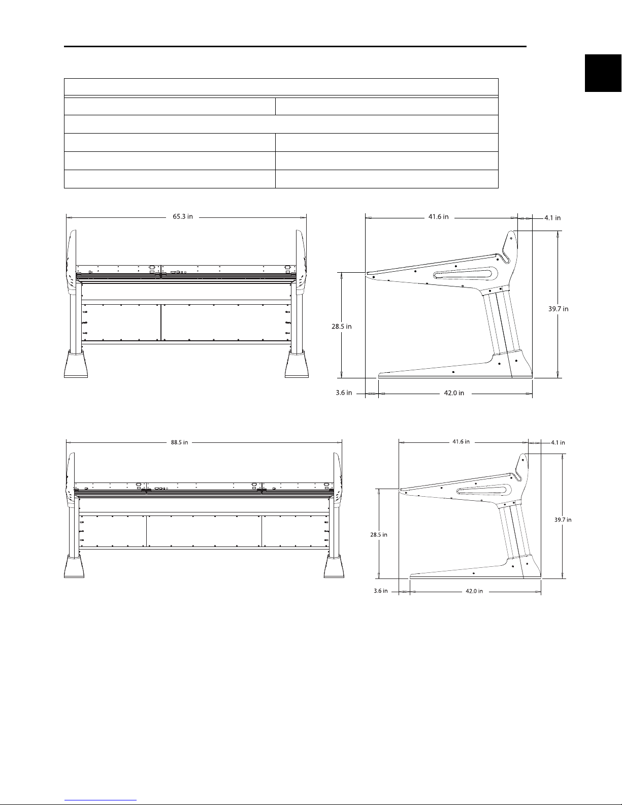
Mechanical Specifications
D-Control Stand Dimensions (not including video display arm)
Maximum Height 39.7 inches (100.9 cm)
Maximum Width
Main Unit with 1 Fader Module (16-channel system) 65.3 inches (165.9 cm)
Main Unit with 2 Fader Modules (32-channel system) 88.5 inches (224.8 cm)
Maximum Depth 45.7 inches (116.1 cm)
Figure 1. Stand dimensions for a 16-fader D-Control system
Figure 2. Stand dimensions for a 32-fader D-Control system
Chapter 1: Introduction to D-Control 5
Page 14

D-Control Guide6
Page 15
Chapter 2: D-Control Overview
Monitor Section
Dynamics Section
EQ Section
Transport
Section
Channel
Strip Master
section
Channel
Strip Master
Function controls
Custom Fader
controls
Focus
Talkback switch
Bank
Select
section
Window
Management
section
Session
Management
section
Soft Keys
section
Bank/Nudge
section
Zoom/Navigation
section
Miscellaneous
controls
Meter display
Talkback Microphone
Time Scale displays and Location indicators
Display Arm Housing Display Shelf
Automation Mode
controls
Channel
Strip Master
Assign and
(also on
left side of
Main Unit)
Display controls
Channel Strip
D-Control Main Unit
Main Unit Top Panel
Figure 3. D-Control Main Unit top panel
Chapter 2: D-Control Overview 7
Page 16

Meter Display
The Meter display on the D-Control Main Unit can be set to
show the output levels, or levels associated with a track or
plug-in. See “Meter and Time Code Displays (Main Unit)” on
page 124.
Time Scale Displays and Location Indicators
Window Management and Session Management
Sections
The Window Management and Session Management sections
on the D-Control Main Unit include controls for opening and
closing Pro Tools windows, and managing and saving
Pro Tools sessions. See “Window Management Section” on
page 101 and “Session Management Section” on page 102.
The Time Scale displays and Location indicators mirror the
corresponding indicators in Pro Tools. See “Meter and Time
Code Displays (Main Unit)” on page 124.
Display Shelf and Display Arm Housing
D-Control gives you two options for using a video display:
You can place a free-standing display on the display shelf, or
you can install a VESA TFT display on the included display
arm. See “Installing a Video Display” on page 27.
Focus Channel Strip
The Focus Channel Strip on the D-Control Main Unit is used
to bring the controls of any channel strip in a session to the
center of the control surface, bringing them to the center mix
position. See “Channel Strips” on page 49.
Dynamics and EQ Sections
The D-Control Main Unit provides dedicated Dynamics and
EQ sections for plug-ins that support D-Control Dynamics
and EQ plug-in mapping. See Chapter 7, “Plug-in Controls.”
Monitor Section
The Monitor section on the D-Control Main Unit includes a
full set of controls for the control room monitoring, headphone/cue, and talkback/listenback sections of D-Control. See
“Monitor Section Controls” on page 115.
Zoom/Navigation Section
The Zoom/Navigate section on the D-Control Main Unit is
used to control navigation, display, and selections in the
Pro Tools Edit window. See “Zoom/Navigate Section” on
page 97.
Soft Keys Section
The Soft Keys section on the D-Control Main Unit provides access to a wide range of Pro Tools commands directly from the
control surface. It also provides access to preferences and settings specific to D-Control. See “Soft Keys Section” on
page 103.
Miscellaneous Controls
The Miscellaneous Controls section on the D-Control Main
Unit includes controls for basic Pro Tools editing and display
functions. See “Miscellaneous Controls Section” on page 112.
Transport Section
The Transport section on the D-Control Main Unit includes
two complete sets of transport controls, switches for setting
the transport mode, scrub/shuttle controls, as well as advanced audition and locate controls. See “Transport Section”
on page 91.
Channel Strip Master Section
The Channel Strip Master section is a set of controls that
appears on both the left and right sides of the D-Control Main
Unit, allowing easy access to powerful assignment, display,
and channel function controls from any mixing position. See
“Channel Strip Master Section” on page 57.
Custom Fader Controls
The Custom Fader controls in the D-Control Main Unit invoke a special set of D-Control modes, called Custom Fader
modes, which let you set aside and customize channel strips
for display and editing of a variety of functions. See “Custom
Fader Controls” on page 67.
Bank/Nudge and Bank Select Sections
The Bank/Nudge and Bank Select sections on the D-Control
Main Unit are used to control the display of Pro Tools tracks
on the control surface, in both Normal and Custom Fader
modes. See “Bank/Nudge Section” on page 98 and “Bank Select Matrix” on page 98.
D-Control Guide8
Talkback Switches
Two Talkback switches on the Main Unit provide mirrored
control of the D-Control Talkback function. See “Talkback
Switch” on page 69.
Automation Mode Controls
The Automation Mode controls mirror the function of the
on-screen Automation Mode selector for each track. See “Automation Mode Controls” on page 69.
Page 17
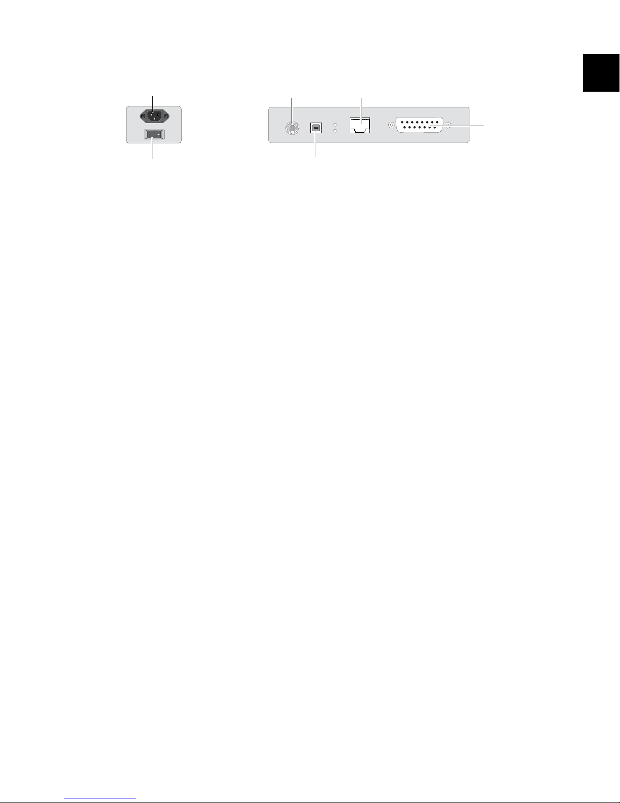
Main Unit Back Panel
Footswitch jack
Keyboard/Trackball
USB connector
Ethernet connector
XMON Monitoring System
connector
AC Power
Power switch
Figure 4. D-Control Main Unit back panel connectors
AC Power
The AC Power connector accepts a standard AC power cable.
The D-Control Main Unit is auto power-selecting (100V to
240V) and automatically works with a standard modular
power cord when connected to an AC receptacle in any
country.
Power Switch
The Power switch applies power to the D-Control Main Unit.
Footswitch Jack
The footswitch jack on the back panel of the D-Control Main
Unit is a 1/4-inch TRS jack that supports two footswitch connections. See “Footswitch Connections” on page 34.
Keyboard/Trackball USB Connector
The USB connector on the back panel of the D-Control Main
Unit links the computer keyboard and trackball on the Main
Unit to the Pro Tools system. See “USB Connections” on
page 34.
Ethernet Connector
The Ethernet connector on the back panel of the D-Control
Main Unit provides communication to Pro Tools. See “Ethernet Connections” on page 33.
XMON Monitoring System Connector
The 15-pin connector on the back panel of the D-Control
Main Unit provides remote control of all audio monitoring
functions from the D-Control Monitoring section. See
“XMON Monitoring System Connection” on page 35.
Chapter 2: D-Control Overview 9
Page 18
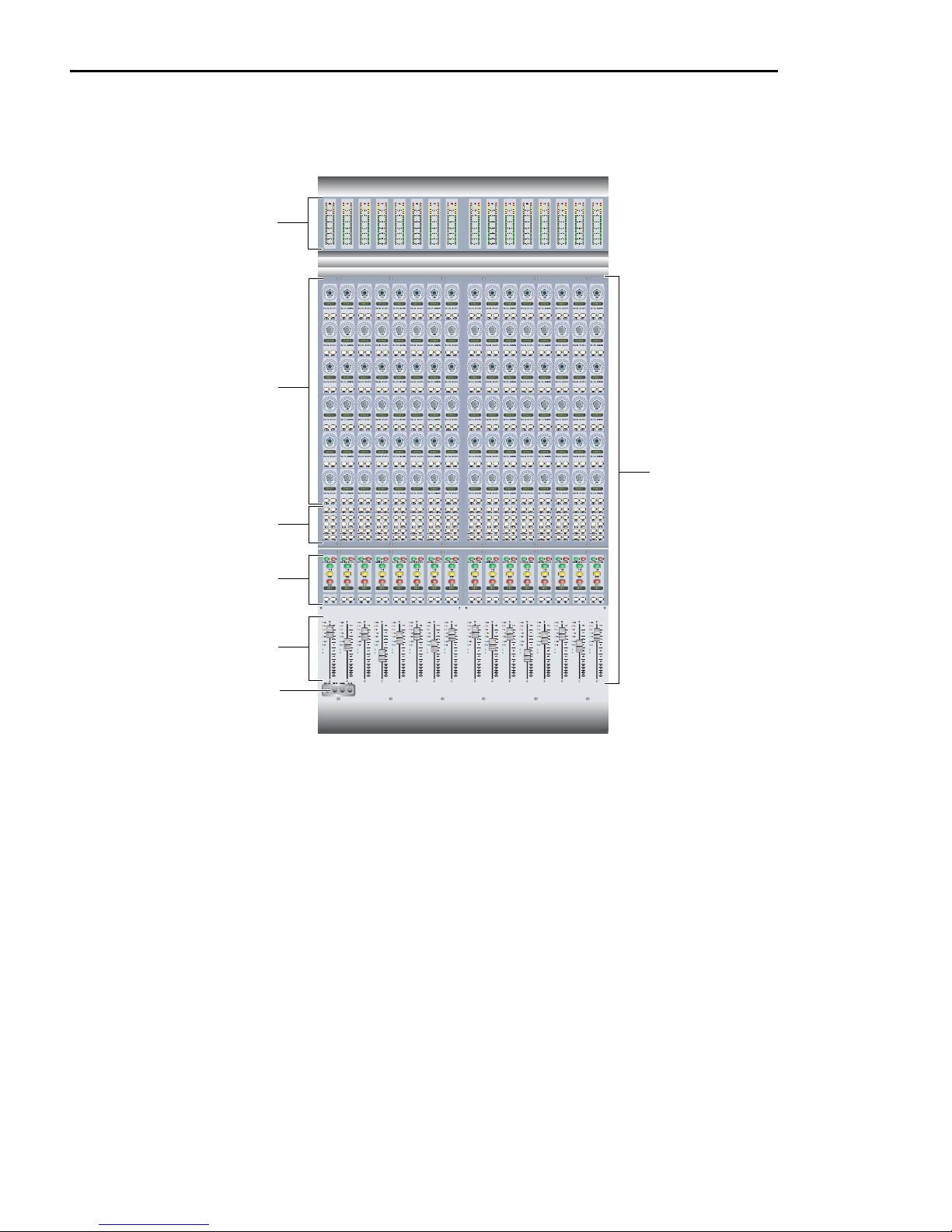
D-Control Fader Module
Channel Strip
Rotary Encoder
section
Meter
section
Channel Strip
Mode controls
Channel faders
Channel Strip
Function controls
Modifier keys
Fader Module Top Panel
Figure 5. D-Control Fader Module top panel
Meter Section
The Meter section on the D-Control Fader Module can display
track levels, plug-in meters, and other parameters depending
on D-Control metering preferences. See “Meter Displays
(Fader Module)” on page 125.
Channel Strip
Each channel strip on the D-Control Fader Module has identical channel controls, including six touch-sensitive rotary encoders, display and mode controls, and a touch-sensitive
fader. See “Channel Strips” on page 49.
Modifier Keys
Each D-Control Fader Module has a set of four switches in its
lower left corner that duplicate the function of the Pro Tools
computer keyboard modifiers. See “Modifier Key Switches” on
page 56.
D-Control Guide10
Fader Module Back Panel
AC Power
The AC Power connector accepts a standard AC power cable.
The D-Control Fader Module is auto power-selecting (100V to
240V) and automatically works with a standard modular
power cord when connected to an AC receptacle in any
country.
Power Switch
The Power switch applies power to the Fader Module.
Ethernet Connector
The Ethernet connector on the back panel of the D-Control
Fader Module provides communication to Pro Tools. See
“Ethernet Connections” on page 33.
Page 19
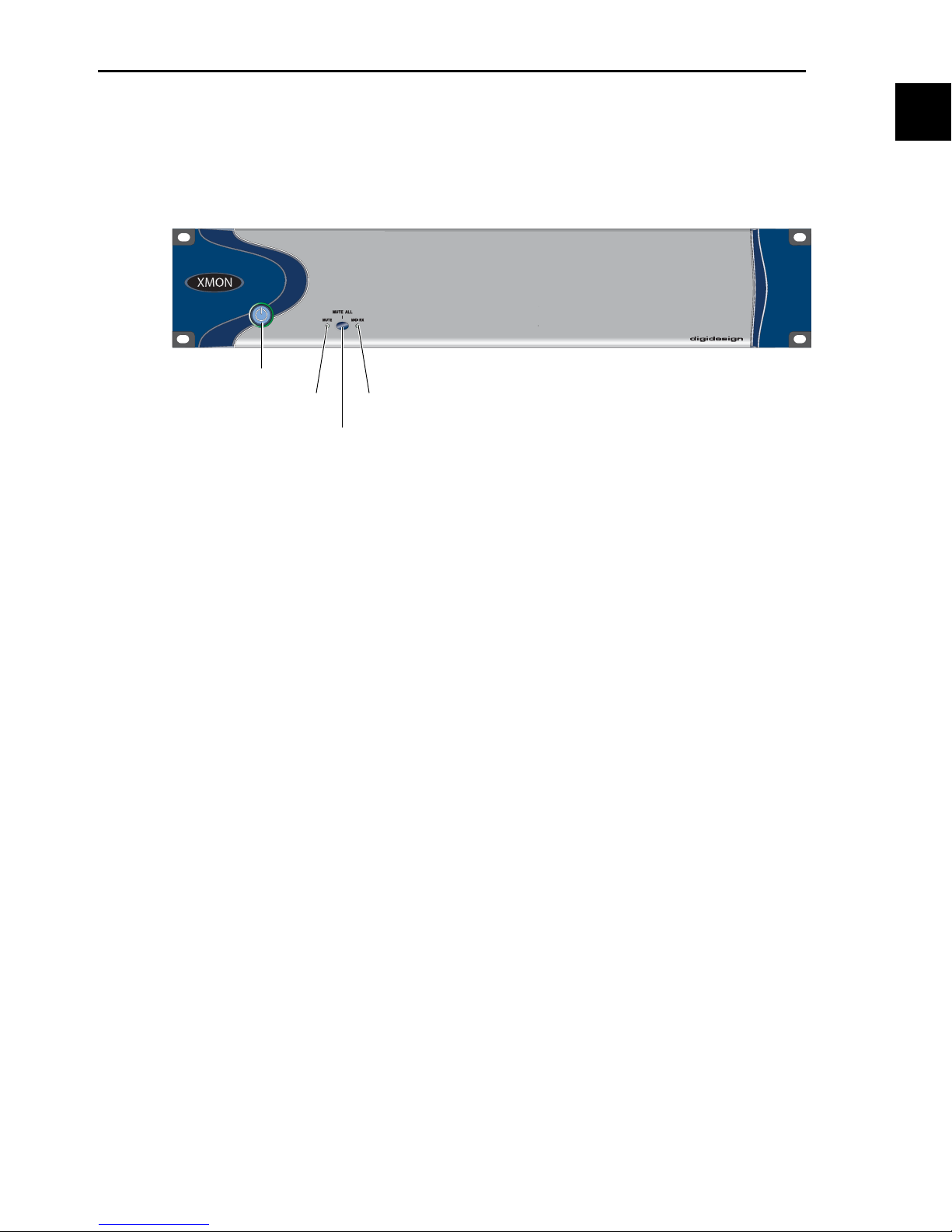
D-Control XMON Interface
Power
switch
MIDI Receive
indicator
Mute
indicator
Mute button
D-Control monitoring is based on the XMON analog interface, which is remotely controlled from the D-Control
monitoring section.
XMON Front Panel
Figure 6. XMON front panel
Power Switch
The Power switch applies power to the XMON Interface.
Mute Indicator
The Mute indicator shows the mute status of XMON.
MIDI Receive Indicator
The MIDI Receive indicator shows MIDI activity between
XMON and D-Control.
Mute Button
The Mute button mutes all XMON outputs. It is not possible
to unmute XMON with this button. The XMON mute state
can only be cleared from the D-Control Monitor section (see
“Monitor Section Controls” on page 115).
Chapter 2: D-Control Overview 11
Page 20
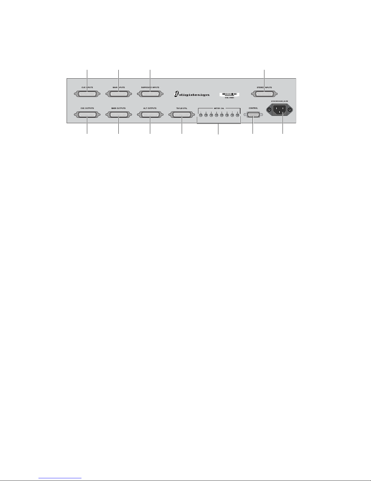
XMON Back Panel
Cue Inputs
Cue Outputs
Main Inputs Surround Inputs Stereo Inputs
Main Outputs Alt Outputs Talkback/ Meter Calibration Control Surface AC Power
Listenback/
Utility
Screws
The back panel of the XMON interface includes connectors for all external analog audio inputs and outputs for D-Control. See
“Audio Connections” on page 35.
Figure 7. XMON back panel
D-Control Guide12
Page 21

Part II: Installation
Page 22

Page 23
Chapter 3: Setting Up D-Control
This chapter explains how to set up 16-fader (Main Unit plus one Fader Module) and 32-fader D-Control systems (Main Unit plus
two Fader Modules).
D-Control Stand
(16-Fader and 32-Fader Systems)
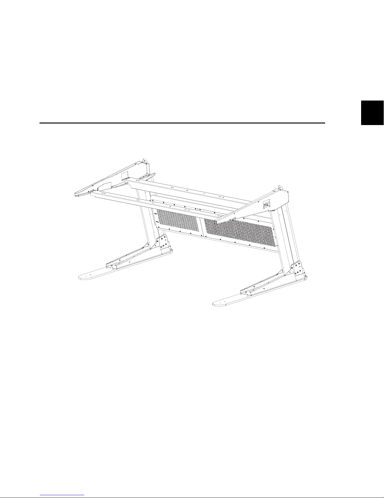
Figure 1. Assembled D-Control stand
The stand configurations for 16-fader and 32-fader systems have similar assembly procedures and the same number of parts (the
crossbar and support rails are longer for a 32-fader system).
Chapter 3: Setting Up D-Control 15
Page 24
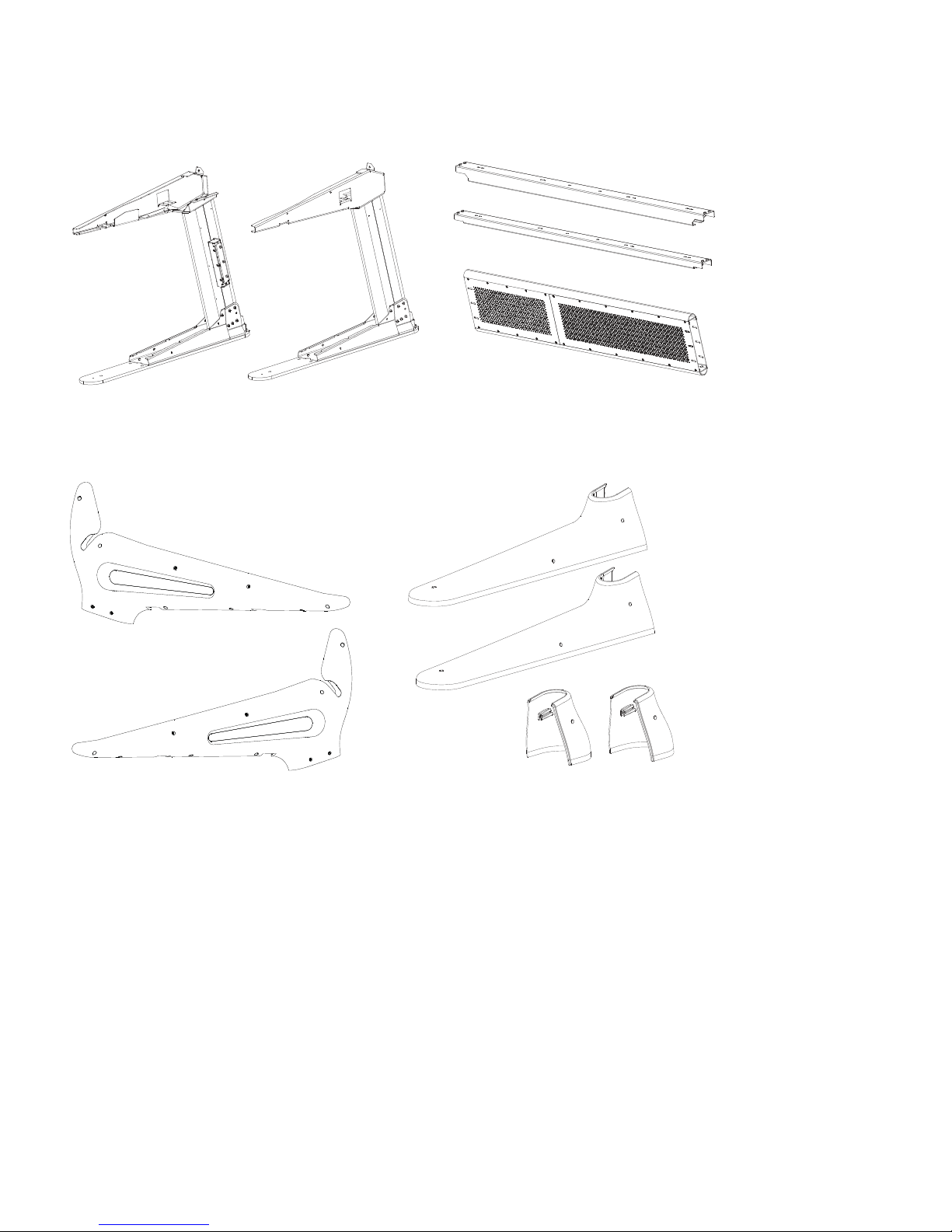
Stand Components
Left leg assembly Right leg assembly Rear crossbar assembly
Front pan support rail
Rear pan support rail
Left and right side caps
(2) Leg front caps
(2) Leg rear caps
Unpack the stand and confirm that you have all of the necessary parts. Figure 2 shows the metal parts of the stand. Figure 3 shows
the plastics parts of the stand. Set the plastic parts aside to protect them from damage during initial assembly.
Figure 2. D-Control metal stand parts
Figure 3. D-Control plastic stand parts
D-Control Guide16
Page 25
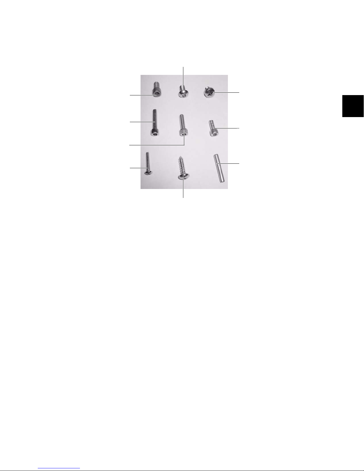
Stand Hardware
1/4-inch-20 x 1/2-inch button head cap screw
1/4-inch-20 x 1/2-inch socket head cap screw
M6 x 8mm Phillips pan head screw
#10-32 x 1/2-inch socket head cap screw
#10-32 x 1-inch socket head cap screw
#10-32 x 3/4-inch socket head cap screw
1/2-inch roll pin
#10 x 3/4-inch Phillips pan head screw
#6-32 x 7/16-inch Phillips pan head machine screw
The following hardware is provided with the D-Control stand (spare pieces may be included).
Figure 4. D-Control assembly hardware for metal and plastic parts
Hardware for Metal Stand Parts
• (14) 1/4-inch-20 x 1/2-inch button head cap screws
• (10) 1/4-inch-20 x 1/2-inch socket head cap screws
• (22) M6 x 8mm Phillips pan head screws
• (8) 1/2-inch-20 x 1-inch socket head cap screws
for leveling the stand (not pictured)
• (3) 1/2-inch roll pins
Hardware for Plastic Stand Parts
• (3) #10-32 x 1/2-inch socket head cap screws
• (4) #10-32 x 3/4-inch socket head cap screws
• (26) #10-32 x 1-inch socket head cap screws
• (8) #10 x 3/4-inch Phillips pan head screws
• (3) #6-32 x 7/16-inch Phillips pan head machine screws
Cabling Accessories
• (14) cable tie mounts
• (8) screw mount cable ties
• (14) cable ties
• (4) Velcro rip ties
• (10) #8 x 1/2-inch self-tapping screws (for use with rip
ties and screw mount cable ties)
Tools for Assembling the Stand
The following tools are included with D-Control:
• 5/32-inch hex driver (for button head cap screws)
• 3/16-inch hex driver (for socket head cap screws)
• 3/8-inch hex driver (for stand leveling screws)
The following additional tools are required to assemble the
D-Control stand:
• #2 Phillips screwdriver (for large Phillips head screws)
• #1 Phillips screwdriver (for small Phillips head screws)
• small hammer (for 1/2-inch roll pins)
The following tools are optional, but will help with assembly:
• rubber mallet for adjusting the stand
• ratcheting nylon strap for closing up the stand
Chapter 3: Setting Up D-Control 17
Page 26
Placement of D-Control
(3) 1/2-inch–20 x 1-inch socket head cap screws
Preparing the Stand Legs
In planning the placement of your D-Control, make sure to
account for the dimensions of the assembled system, allowing
for at least 1 inch (2.5 cm) of open space behind the finished
unit. This meets the ventilation requirements for the D-Control units.
For detailed dimensional information, see “Mechanical Specifications” on page 5.
When assembling the unit, you will need additional clearance
on either side of the unit to push the sides of the stand together in the final steps of assembly. You will also need access
to the rear of the unit to make cable connections.
Before assembling the D-Control stand, make sure the floor in
the installation space is level and the areas directly under the
legs are flat.
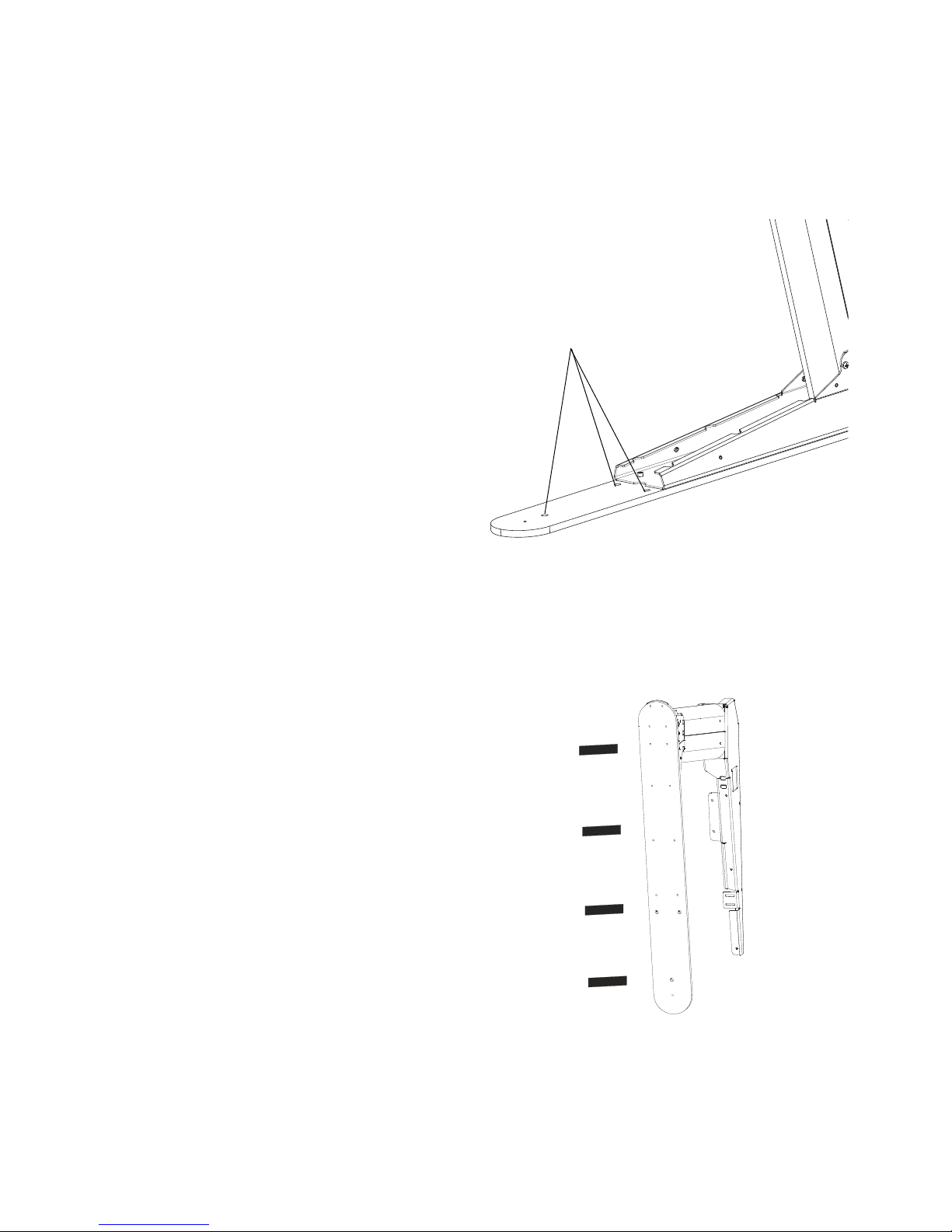
Each stand leg has three holes for leveling screws in its base,
which can be used to fine-tune the leveling of the unit.
Figure 5. Location of leveling screws
If you are placing the unit on a cement or hardwood floor, you
can apply adhesive-backed rubber pads (included) to the bottoms of the legs to protect the floor and help level the stand.
If you are using the leveling screws, you can place rubber pads
directly under the screws to further protect the floor.
Figure 6. Applying rubber pads to bottom of D-Control leg
D-Control Guide18
Page 27
Assembling the Stand
Left stand leg
Right stand leg
Crossbar mounting brackets
Gap between crossbar and
stand leg
Crossbar mounting
bracket
After you have prepared the installation space for D-Control, begin by assembling the metal parts of the stand.
It is important that you first build the stand slightly wider than its final dimensions, and leave all screws loose enough to
allow the stand legs to move side-to-side relative to the rear crossbar and rails. After you install the D-Control units on the
stand, you will then slide the leg assemblies inward and tighten all screws.
To assemble the stand:
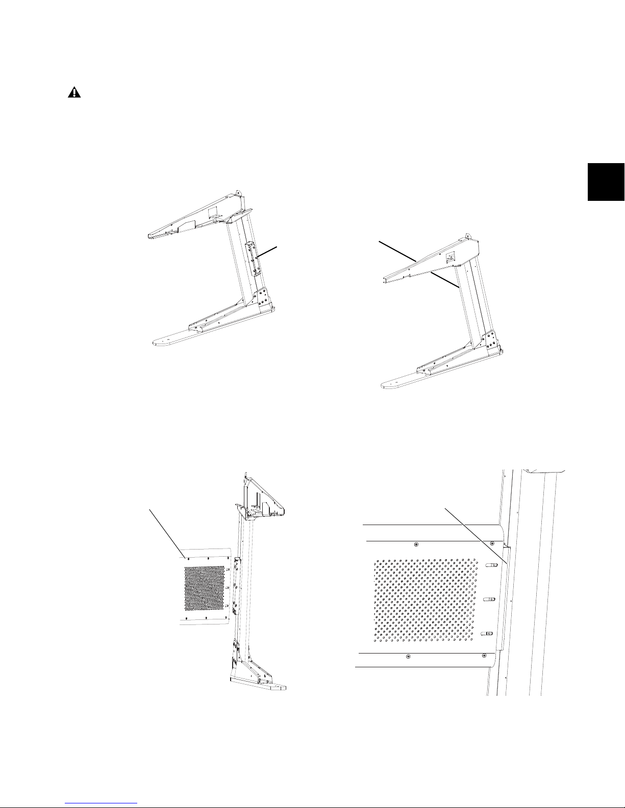
1 Place the right and left leg assemblies upright, and at the approximate width of the rear crossbar assembly. Position the legs so
that their crossbar mounting brackets are on the insides of the legs, facing each other as in Figure 7.
Figure 7. D-Control stand legs positioned with crossbar brackets facing each other
2 Lift the rear crossbar assembly into position and slide it onto the crossbar mounting bracket on each leg. (The two sides of the
crossbar are identical, so it does not matter which side faces front.) Position the legs so there is a small gap between the sides of
the crossbar and the inner surface of each leg. The screw holes in the brackets should be visible in the slots on the crossbar.
Figure 8. Placing the rear crossbar assembly on the mounting bracket (left); Detail of gap between crossbar and leg (right)
Chapter 3: Setting Up D-Control 19
Page 28
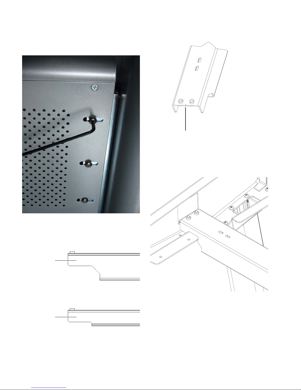
3 Using a 5/32-inch hex wrench, attach the crossbar to the
Rear pan
Front pan
support rail
support rail
Notch indicating left side of rear pan support rail
brackets with 1/4-inch-20 x 1/2-inch button head cap screws
(see Figure 9), using 6 screws on each side (3 in front and 3 in
back). Make sure to leave the screws loose enough so that the
legs can be moved side-to-side relative to the rear crossbar.
5 Position the rear rail so that the edge with the V-shaped
notch points toward the left stand leg.
Figure 11. V-shaped notch in rear pan support rail
6 Lift the rear rail into place so that the rail rests on the rear
rail tabs of the stand legs (see Figure 12). The holes on the ends
of the rail should line up with the slots in the rear rail tabs on
each leg.
Figure 9. Attaching the crossbar
4 Locate the rear pan support rail, which is the larger of the
two rails provided with the stand.
Figure 10. Side view of pan support rails
Figure 12. Rear support rail in place on left stand leg
D-Control Guide20
Page 29
7 Using a 3/16-inch hex wrench, attach the rear rail to the rail
Notch indicating left side of front pan support rail
tabs on each leg from below with 1/4-inch-20 x 1/2 inch
socket head cap screws (see Figure 13), using 2 screws in each
side. Make sure to leave the screws loose enough so that the
leg assemblies can be moved side-to-side relative to the rear
rail.
10 Lift the front rail into place so that the rail rests on the
front rail tabs of the stand legs. The holes on the ends of the
rail should line up with the slots in the front rail tabs on each
leg.
11 Using a 3/16-inch hex wrench, attach the front rail to the
rail tabs on each leg from below with 1/4-inch-20 x 1/2 inch
socket head cap screws, using 2 screws in each side. Make sure
to leave the screws loose enough so that the leg assemblies can
be moved side-to-side relative to the front rail.
Figure 13. Attaching support rail from below
8 Locate the front pan support rail, which is the smaller of the
two rails provided with the stand.
9 Position the front rail so that the edge with the V-shaped
notch points toward the left stand leg.
Figure 15. Front and rear support rails in place on left stand leg
With the rear crossbar, rear support rail and front support rail
in place (see Figure 15), you are now ready to install the
D-Control units on the stand.
Figure 14. V-shaped notch in front pan support rail
Chapter 3: Setting Up D-Control 21
Page 30
Installing D-Control Units
MainFader
Main
Fader
16-fader system, Main on right
16-fader system, Main on left
Fader
MainFader
MainFader
Main
Fader Fader
Fader
Fader
32-fader system, Main in center
32-fader system, Main on right
32-fader system, Main on left
After the stand has been assembled, the next step is preparing
the D-Control Main Unit and Fader Modules for installation.
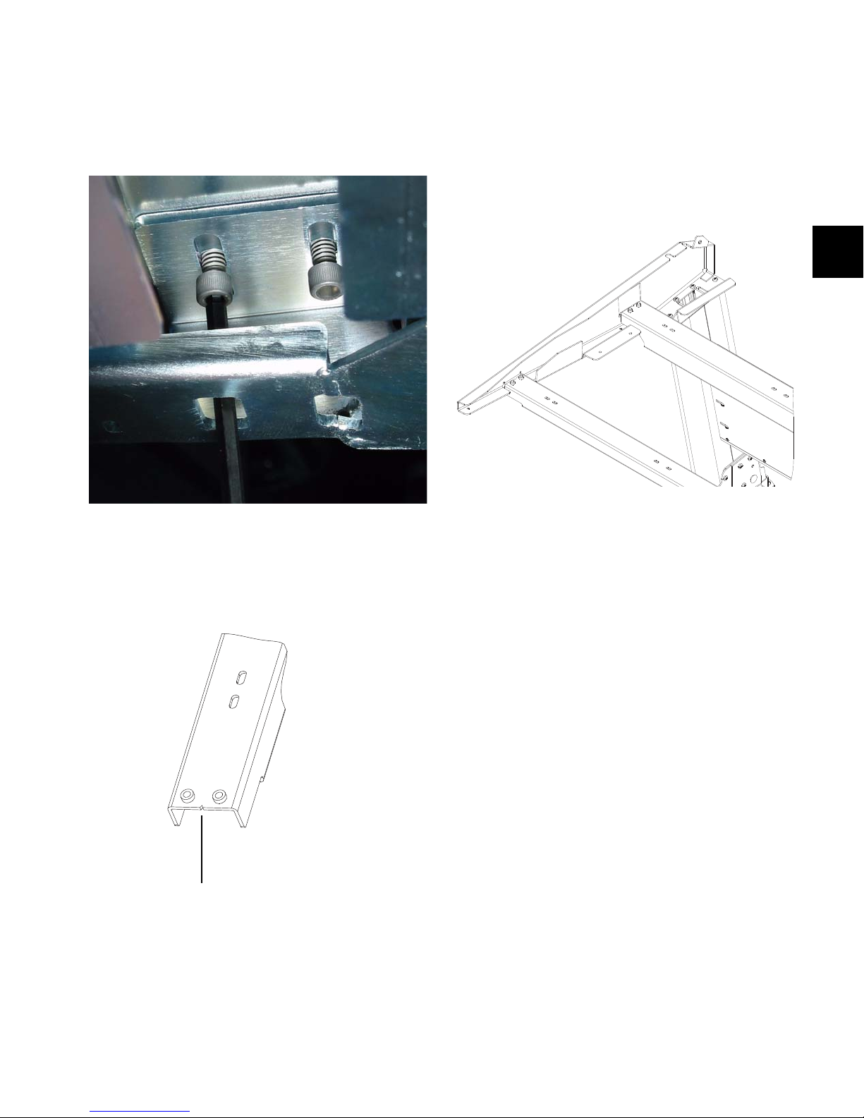
Attaching the Spacer Plate
A metal spacer plate goes between each D-Control unit on the
D-Control stand.
Figure 16. D-Control spacer plate (removed from a Fader Module)
A spacer plate is pre-installed on the right side of each Fader
Module. Depending on the size and configuration of your
D-Control system, you may need to move the plate from one
of the Fader Modules to the Main Unit. Refer to the section below for your system configuration.
32-Fader System
If you are building a 32-fader D-Control, you can place the
Main Unit to the left, to the right, or in between the two Fader
Modules.
16-Fader System
If you are building a 16-fader D-Control, you can place the
Main Unit either to the left or to the right of the Fader
Module.
Figure 17. 16-channel configurations
If you are placing the Main Unit to the left of the Fader
Module, you need to move the spacer plate from the Fader
Module to the Main Unit. Refer to “Moving the Spacer Plate”
on page 23 before installing the units on the stand.
If you are placing the Main Unit to the right of the Fader
Module, you can use the spacer plate on the Fader Module as
pre-installed. Proceed to “Installing the Units on the Stand”
on page 24.
Figure 18. 32-channel configurations
If you are placing the Main Unit to the left or in between the
two Fader Modules, you need to move the spacer plate from
the far-right Fader Module to the Main Unit. Refer to “Moving
the Spacer Plate” on page 23 before installing the units on the
stand.
If you are placing the Main Unit to the right of the two
Fader Modules, you can use the spacer plates as pre-installed
on the Fader Modules. Proceed to “Installing the Units on the
Stand” on page 24.
D-Control Guide22
Page 31

Moving the Spacer Plate
long screws (5)
long screws (2)
Top roll pin
location
Front roll pin
location
Leveling the Pins on the Rightmost Unit
When installing any Fader Modules on the right of the Main
Unit, you will need to remove the spacer plate and its screws
from the far right Fader Module and place them on the right
side of the Main Unit.
Do not use a power screwdriver or similar high-torque
device to remove and replace the screws for the spacer
plate, as it might strip the threads in the screw housing.
To move the spacer plate:
1 Remove the screws holding the spacer plate in place. Make
sure to note the location of the longer screws (2 in the front
and 5 in the back) as you remove them.
Fader Modules and Producer’s Desks ship with two pins in
their right side to help anchor the units together on the stand.
(These pins are not needed on the rightmost unit in your configuration, and can be removed.)
To level the roll pins on the rightmost unit:
1 Identify the unit that will occupy the rightmost position in
your configuration.
2 Use a small hammer to tap in the two pins the right side of
until they are flush with the side of the unit. (There is no stop
inside the pin rails, so you will be able to install new pins if
you expand your system later.)
Figure 19. D-Control spacer plate (removed from a Fader Module)
2 Remove the spacer plate from the right side of the Fader
Module.
Figure 20. Removing the spacer plate from a Fader Module
3 Remove the corresponding screws from the right side of the
Main Unit, and save them for the Fader Module.
4 Position the spacer plate on the right side of the Main Unit,
and attach it in place with the screws that originally held it on
the Fader Module. Make sure to note the location of the longer
screws.
Figure 21. Installing the roll pin in the top of a D-Control unit
Figure 22. Installing the roll pin in the front of a D-Control unit
5 Place the remaining screws in the side of the Fader Module.
Make sure to note the location of the longer screws.
The holes on the spacer plate are countersunk for installation on the right side of a unit. Do not attach the spacer
plate to the left side of any D-Control unit.
Chapter 3: Setting Up D-Control 23
Page 32

Installing the Units on the Stand
After the D-Control Main Unit and Fader Modules are prepared for installation, the units are placed on the stand in the
appropriate order for your configuration. Install the units
from left to right on the stand.
To install the D-Control units on the stand:
1 Lift the first unit into place on the stand so the channels in
the bottom of the unit go over the rear and front rails of the
stand.
3 Lift successive units into place on the stand, being careful
not to bend the pins in the units you installed previously.
4 Slide the units together, guiding the pins in each unit into
the corresponding holes in the side of the next unit.
5 Attach the units to the front and rear rails from below with
M6 x 8mm Phillips pan head screws, using a total of 6 screws
for the Main Unit (3 each in the front and rear rails) and a total
of 4 screws for the Fader Module (2 each in the front and rear
rails). Make sure to leave these screws loose enough so that the
units can still move side-to-side relative to the rails.
Figure 23. Placing a Fader Module on the stand
2 Slide the unit to the left side of the stand, leaving a gap of
about an inch (2 cm) between the side of the unit and the
flange on the inside of the stand.
Figure 25. Attaching a unit to the rails from below
Figure 24. Leaving a gap between the unit and stand
D-Control Guide24
Page 33

Closing Up the Stand
(2) M6 x 8mm Phillips pan head screws
Next, you will close up the stand and finish attaching the
units.
To close up the stand:
1 Move the stand legs together to completely close the gap be-
tween the stand and the outer units. (You may want to tap the
base of the legs with a rubber mallet to help move them into
place.)
2 Use a ratcheting nylon strap to compress the stand legs to-
gether.
Figure 26. Using a nylon strap on the stand legs
3 If there is still any gap between the rear crossbar assembly
and either of the legs, position the crossbar so that the gap is
equal on both sides.
4 Tighten the 6 button cap screws on each side of the rear
crossbar.
5 If necessary, use the ratcheting nylon strap to compress the
D-Control units together by running the strap around the top
part of the legs and across the D-Control units as shown in
Figure 27. Make sure the nylon strap does not contact any
switches or encoders on the surface.
Figure 27. Using a nylon strap on the D-Control units
6 Tighten the 2 socket head cap screws on each side of the
front and rear rails from below.
7 Attach the outside (rightmost and leftmost) units to the
flanges on the legs from below with M6 x 8mm Phillips pan
head screws. Tighten these screws.
Figure 28. Attaching a unit to the leg flanges (view from below)
8 Tighten the Phillips pan head screws that attach the D-Con-
trol units to the front and rear rails from below.
9 Remove the nylon strap.
Chapter 3: Setting Up D-Control 25
Page 34

Installing the Plastic Side Caps
Remove this screw
(6) #10-32 x 1-inch socket head cap screws
(3) #10 x 3/4-inch Phillips pan head screws
(1) #6-32 x 7/16-inch Phillips pan head
machine screw
With the D-Control units in place and attached to the stand
rails, you are now ready to install the plastic side caps.
Do not use a power screwdriver or similar high-torque
device to attach the plastic side caps, as it may distort
or damage the caps.
To install the plastic side caps:
1 On each side of the system, locate the pair of #6-32 machine
screws, arranged one above the other, near the front of each
unit. Remove the lower of the two screws from each side of the
unit.
3 Place the plastic side caps over each side of the unit, starting
by hooking the front of each cap around the front part of the
stand leg, then sliding the cap backward into place. The holes
on the cap should line up with holes on the stand.
Figure 31. Placing a plastic side cap on the stand
4 Attach each plastic side cap with the screws indicated in Fig-
ure 32. Leave the screws loose until you have placed all of the
screws, then go back and tighten all of the screws carefully.
Figure 29. Removing the machine screw from a unit
2 Locate the two small blue rubber meter break caps and in-
stall them in the inside of the plastic side caps.
Figure 30. Installing a meter break cap in a plastic side cap
Figure 32. Attaching the plastic side caps
D-Control Guide26
Page 35

Installing the Plastic Leg Caps
(2) #10-32 x 3/4-inch socket head
(1) #10-32 x 1/2-inch socket head
cap screws
cap screw
(2) #10-32 x 1-inch socket head
cap screws
(3) #10-32 x 1-inch socket head cap screws
You can install the D-Control plastic leg caps at any time.
To protect the plastic leg caps from damage, install them
last, after you have finished installing and configuring
any other D-Control components and moved the system
into place. If necessary, continue with other installations
and return to these steps when you are finished.
Installing a Video Display
D-Control gives you two options for using a video display:
Free-Standing Display The display shelf on D-Control can support a free-standing flat screen display.
Arm-Mounted TFT Display Using the video display arm included with the Main Unit, you can mount a TFT-type display
on D-Control.
General instructions for installing each display are given in
the following sections. For details on setting up a particular
display, refer to the manufacturer’s instructions.
Installing a Free-Standing Display
The display shelf on the D-Control Main Unit can support a
free-standing flat screen display (such as an Apple Cinema display) up to a 20-inch screen size. (Larger displays may obstruct
the view of the meter bridge on the Main Unit.)
To install a free-standing display:
1 Remove the display shelf panel from the Main Unit.
Figure 33. Plastic leg cap placement
To install the plastic leg caps:
1 Place the front leg caps over each leg. Attach each front cap
with the screws indicated in Figure 34.
Figure 34. Attaching the plastic front leg caps
2 Place the rear leg caps over each leg. Attach each rear cap
with the screws indicated in Figure 35.
Figure 36. Removing the display shelf from the Main Unit
Figure 35. Attaching the plastic rear leg caps
Chapter 3: Setting Up D-Control 27
Page 36
2 Replace the mounting post housing on the underside of the
display shelf panel with the provided cover plate.
Figure 37. Mounting post housing (back of display shelf panel)
3 Run the display cabling through the cable port in the dis-
play shelf panel.
4 Route the display cabling down through the Main Unit and
through the cable port in the bottom of the Main Unit. (You
may need to remove a panel covering this cable port.)
Installing an Arm-Mounted TFT Display
The articulated video display arm included with the D-Control Main Unit can support a VESA-style display that weighs
up to 20 pounds (9 kg).
The video display arm is packaged separately and includes
hardware that is not needed for D-Control. The
arm-mounting hardware is pre-installed in the bottom of
the Main Unit.
To install an arm-mounted TFT display:
1 Mount the video display on the display arm assembly ac-
cording to the manufacturer’s instructions.
2 Discard the mounting post included with the monitor arm
assembly. A correctly sized replacement post is included with
the D-Control Main Unit.
3 Install the new mounting post in the Main Unit. Note the
orientation of the post (the side with the longer slot faces the
back of the unit).
Figure 38. Cable port in bottom of Main Unit (view from below)
5 Replace the display shelf panel on the Main Unit.
6 Place the display on the display shelf.
D-Control Guide28
Figure 39. Installing the mounting post in the Main Unit
4 Run the display cabling through the cable port behind the
mounting post housing (you many need to remove the display shelf to route any connectors through the port).
5 Route the display cabling down through the Main Unit and
through the cable port in the bottom of the Main Unit. (You
may need to remove a panel covering this cable port. See Figure 38.)
6 Place the display arm collar over the mounting post assem-
bly. Do not tighten the set screw for the collar.
Page 37

7 Place the display arm assembly on the mounting post as-
sembly.
10 Insert the top cap/threaded rod in the mounting post as-
sembly and tighten it with the provided wrench.
Figure 40. Placing the arm assembly on the mounting post
8 Adjust the display arm collar so that its stops prevent the
arm assembly and video display from hitting the D-Control
meter bridge. In most cases, the setscrew should not go into
the hole in the mounting post assembly, but should be
slightly to the right of the hole and the cable port as shown in
Figure 41.
Figure 41. Detail of display arm collar and setscrew
9 Tighten the setscrew to fix the collar in place.
Figure 42. Attaching the arm assembly with the top cap/threaded rod
Figure 43. Installed arm mount assembly and video display
Chapter 3: Setting Up D-Control 29
Page 38
Mounting D-Control Cables (Optional)
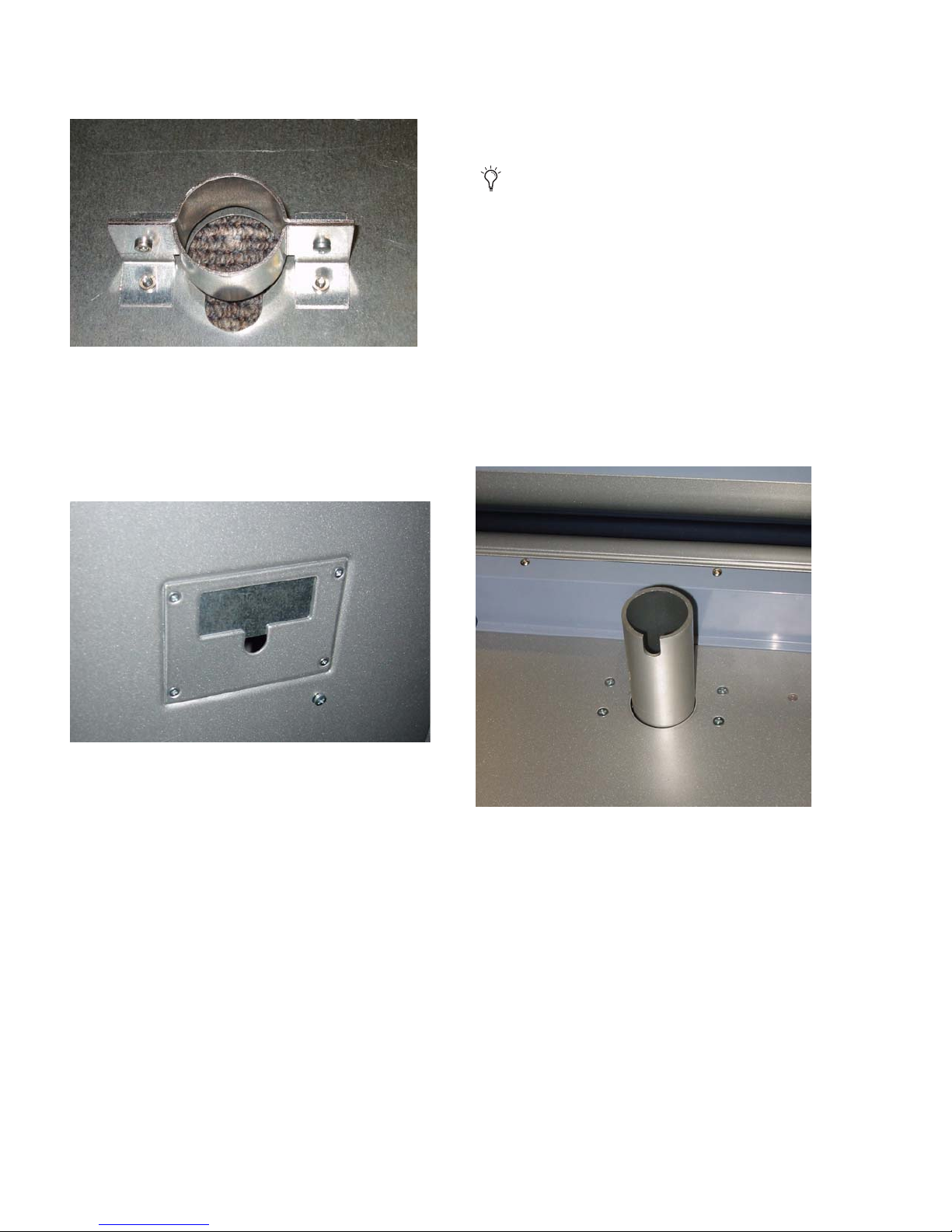
Three different kinds of cable ties are provided with D-Control.
Vel cro R i p T ies These ties can be affixed to the D-Control
stand legs. Two pre-drilled holes inside each leg accept #8 x
1/2-inch self-tapping screws.
Screw-Mount Ties These ties can be affixed to the D-Control
stand legs with the #8 x 1/2-inch self-tapping screws.
Adhesive-Backed Ties These self-sticking tie mounts let you
place cable ties anywhere on the D-Control unit, and can be
used to dress cables or to mount an Ethernet hub under the
unit.
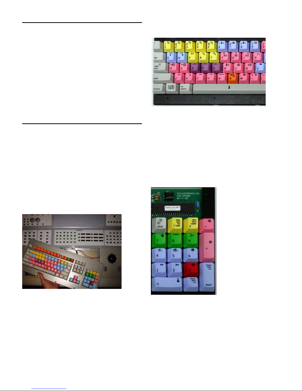
Reconfiguring the D-Control Keyboard
for a Windows System
The computer keyboard on the D-Control Main Unit ships
with a Mac keyboard configuration.
If you will be using D-Control with a Windows-based
Pro Tools system, you will need to reconfigure the computer
keyboard.
To reconfigure the D-Control computer keyboard for Windows:
1 Using a 5/64-inch hex wrench, remove the screws in the
computer keyboard panel and detach it from the D-Control
Main Unit.
5 Install the included Start (or “Windows”) keys to replace the
Alt/Option keys.
Figure 45. Windows keys in place on alpha keyboard
6 Remove the Equals (=) key, also called “Capture” key, from
the numeric keypad.
7 Move the Slash (/) key, also called the “Enter Start End
Length” key, to replace the Equals key.
8 Move the Asterisk (*) key, also called the Enter Main Counter
key, to replace the Slash key.
9 Move the Minus (–) key to replace the Asterisk key.
10 Remove the Plus (+) key and install the included dou-
ble-sized plus key to replace the old Plus and Minus keys.
Figure 44. Removing the computer keyboard from the Main Unit
2 Locate the switch on the printed circuit board under the
keyboard and move it to the opposite position.
3 Remove the two Apple Command (a) keys from either side
of the Spacebar on the alpha keyboard.
4 Move the Alt/Option keys inward to replace the Apple Com-
mand keys.
D-Control Guide30
Figure 46. Windows keys in place on the numeric keypad
11 Replace the computer keyboard panel on the D-Control
Main Unit and reattach its screws.
Page 39

Moving the Keyboard and Trackball
(Optional)
You can move the trackball on the D-Control Main Unit to the
left of the computer keyboard.
To move the keyboard and trackball:
1 Using a 5/64-inch hex wrench, remove the screws in the
computer keyboard panel and the trackball panel on the
D-Control Main Unit.
6 Locate the USB connector on the printed circuit board, and
connect your trackball or mouse to it.
7 Connect the Molex plug you disconnected in Step 3 to the
P2 connector on the printed circuit board. Make sure you fit
the connector and plug together correctly (so that the plug
snaps into place) to maintain polarity of this connection.
8 Route the cable of your trackball or mouse through the slot
in the blank plate.
9 Attach the blank plate to the Main Unit.
2 Exchange the position of the trackball and keyboard panels,
and carefully rearrange their cables underneath the panels.
3 Reattach the computer keyboard and trackball panels to the
Main Unit.
Figure 47. Trackball located on left side of keyboard on the Main Unit
Replacing the Trackball with an
External Trackball or Mouse (Optional)
If you prefer to work with your own trackball or mouse, you
can remove the D-Control trackball from the D-Control Main
Unit and replace it with the provided blank plate, and place
your USB-compatible trackball or mouse on top of the blank
plate.
Reinstalling the Trackball
If you need to reinstall the factory trackball on a D-Control
Main Unit, carry out the following procedure.
To replace the trackball:
1 Using a 5/64-inch hex wrench, remove the blank plate from
the Main Unit.
2 Disconnect the Molex plug from the P2 connector on the
printed circuit board.
3 Disconnect the external trackball or mouse from the USB
connector on the printed circuit board.
4 Remove the screws holding the printed circuit board to the
bottom of the blank plate. Set the blank plate aside.
5 Locate the D-Control trackball plate and install the printed
circuit board on the underside of the trackball plate.
6 Connect the Molex plug that runs from the D-Control track-
ball assembly to the P1 connector on the printed circuit board.
Make sure you fit the connector and plug together correctly
(so that the plug snaps into place) to maintain polarity of this
connection.
7 Connect the Molex cable that comes from under the D-Con-
trol keyboard to the connector on the D-Control trackball assembly.
8 Reattach the trackball plate to the Main Unit.
To remove the trackball:
1 Using a 5/64-inch hex wrench, remove the trackball plate
on the D-Control Main Unit.
2 Disconnect the Molex plug from the P1 connector on the
printed circuit board on the bottom of the trackball plate.
3 Disconnect the Molex plug that comes from under the
D-Control keyboard from the trackball assembly.
4 Remove the screws holding the printed circuit board to the
trackball plate. Set the D-Control trackball plate aside.
5 Locate the blank plate and install the printed circuit board
on the underside of the blank plate.
Chapter 3: Setting Up D-Control 31
Page 40

D-Control Guide32
Page 41

Chapter 4: Connecting D-Control
Footswitch jack
Keyboard/Trackball
USB connector
Ethernet connector
XMON Monitoring System connector
D-Control Connections
D-Control units require power, Ethernet and USB connections to operate with Pro Tools. An optional footswitch connection is
also available on the Main Unit. The connectors on the back panel of the D-Control Main Unit are shown in Figure 48.
Be sure to make all connections with your D-Control units and computer turned off.
Figure 48. D-Control Main Unit back panel connectors
Power Connections
Each D-Control unit (Main Unit and Fader Modules) and the
XMON Monitor Interface requires its own power connection.
D-Control Main Units, Fader Modules, and XMON Interfaces
are auto power-selecting (100V to 240V) and automatically
work with a standard modular power cord when connected to
an AC receptacle in any country. A power cable is provided
with each D-Control unit and the XMON interface.
To make D-Control power connections:
For each D-Control unit and the XMON Interface, connect
the included AC power cord the unit and to a power source.
Ethernet Connections
Each D-Control unit communicates with Pro Tools using
Ethernet. An Ethernet cable is included with each D-Control
unit. A 10-BaseT Ethernet hub (not included) is required to
connect D-Control units to the host computer.
To make D-Control Ethernet connections:
1 Install the Ethernet hub according to its instructions, apply
power to it, and verify that it is functioning properly.
2 Connect the Ethernet hub to the Ethernet port on your
computer.
3 For each D-Control unit, connect one end of the supplied
Ethernet cable to a port on the Ethernet hub, and the other
end to the Ethernet port on the back of the unit. Do not use
any port labelled for LAN connections.
Connection sequence to the Ethernet hub does not matter, because the order of the units can be configured
from within Pro Tools.
Chapter 4: Connecting D-Control 33
Page 42

Using D-Control on an Ethernet Network
Footswitch Connections
You can purchase a combined 10/100-BaseT Ethernet hub that
can simultaneously support D-Control over 10-BaseT and
other network traffic over 100-BaseT. This will allow you to
use D-Control over a local area network.
Moderate network traffic (such as e-mail) should not affect
communication between D-Control and the computer. If your
network experiences heavy traffic, you may want to create a
dedicated Ethernet network for D-Control.
Controlling Pro Tools Systems Over a Network
When D-Control is connected to an Ethernet network, it will
be available to be declared by any Pro Tools system on that
network. This lets you control different Pro Tools systems on
the network with a single D-Control console. (You can only
control one Pro Tools system at a time.)
USB Connections
The computer keyboard and trackball on the D-Control Main
Unit use a USB connection to communicate with the host
computer. A USB cable is required (not included).
The D-Control USB connection supports the use of a USB hub,
if your system has one. A powered USB hub is not required.
You can connect two SPST (single-pole, single-throw) footswitch units to the D-Control Main Unit to control any of the
following functions:
• Starting and stopping Pro Tools playback
• Starting Pro Tools recording
• Toggling Talkback on and off
The footswitch connector is a single 1/4-inch TRS jack on the
back panel of the D-Control Main Unit.
To wire a TRS connector for the D-Control footswitch jack:
Use the following wiring convention: Tip = Footswitch 2,
Ring = Footswitch 1, Sleeve = Ground.
To make the D-Control USB connection:
Connect one end of a USB cable to the USB port on the back
panel of the D-Control Main Unit, and the other end to the
USB port on the computer or USB hub.
D-Control Guide34
Page 43

Audio Connections
Cue Inputs
Cue Outputs
Main Inputs Surround Inputs Stereo Inputs
Main Outputs Alt Outputs Talkback/ Meter Calibration Control Surface AC Power
Listenback/
Utility
Screws
D-Control monitoring is based on the XMON analog interface, which is remotely controlled from the D-Control monitoring section. All external analog audio inputs and outputs for control room monitoring and studio communication are connected to the
XMON interface.
XMON provides 18V phantom for its three external mic inputs (External Talkback Mic, Listen Mic 1, Listen Mic 2).
All audio connections are made with standard DB-25 connectors. The back panel of the XMON is shown in Figure 49.
Figure 49. XMON back panel
XMON Monitoring System Connection
D-Control connects to XMON with a single 15-pin cable. A 50-foot (15.25 m) cable is included with the D-Control Main Unit.
The system supports up to an 80-foot (24.5 m) cable.
To connect the XMON to D-Control:
1 Connect the included AC power cord to the back panel of the XMON and to a power source. A surge protected power source
is highly recommended.
2 Connect one end of the included XMON cable to the Control Surface port on your XMON unit, and the other end to the 15-pin
Control port on the back panel of the D-Control Main Unit.
Chapter 4: Connecting D-Control 35
Page 44

Control Room Monitoring Connections
AFL/PFL
Input
(2 channels)
Main
Input
(8 channels)
Surround
Input
(8 channels)
Stereo 1
Input
(2 channels)
Stereo 2
Input
(2 channels)
Stereo 3
Input
(2 channels)
Stereo 4
Input
(2 channels)
Listen
Mic 1
Listen
Mic 2
Level
Level
Input
Source
Select
AFL/PFL
Level
Pro Tools
Solo
Command
Mono
Summing
Level, Dim,
Solo, Mute,
Trim + Cal
Control Room
Output Select
Main Output
(8 channels)
Alt Output
(8 channels)
Mini Output
(2 channels)
[To Cue System]
Figure 50. Control room monitoring system block diagram
Inputs
Outputs
• Main Inputs (8 channels), balanced, +4 dBu (from Pro Tools)
• Surround Inputs (8 channels), balanced, +4 dBu
• Stereo 1 Inputs (2 channels), balanced, +4 dBu/–10dBV
• Stereo 2 Inputs (2 channels), balanced, +4 dBu/–10dBV
• Stereo 3 Inputs (2 channels), balanced, +4 dBu/–10dBV
• Stereo 4 Inputs (2 channels), balanced, +4 dBu/–10dBV
• AFL/PFL Inputs (2 channels), balanced, +4 dBu
• Listen Mic 1 (external), mic level (XMON provides 18V phantom power)
• Listen Mic 2 (external), mic level (XMON provides 18V phantom power)
• Main Control Room Outputs (8 channels), balanced or unbalanced, +4 dBu
• Alt Control Room Outputs (8 channels), balanced or unbalanced, +4 dBu
• Mini Control Room Outputs (2 channels), balanced or unbalanced, +4 dBu
D-Control Guide36
Page 45

Headphone/Cue System Connections
Main Monitor
Input
Cue 1
Input
(2 channels)
Cue 2
Input
(2 channels)
Cue 3
Input
(2 channels)
Internal
Talkback
Input
External
Talkback
Input
Talkback
switch
Talkback
Assign
Internal
Talkback
Level
External
Talkback
Level
Talkback/Slate Out
(1 channel)
Cue 1 Out
(2 channels)
Cue 2 Out
(2 channels)
Cue 3 Out
(2 channels)
HP Out
(2 channels)
Studio LS
(2 channels)
(2 channels)
[from Control Room System]
Figure 51. Headphone/Cue system block diagram
Inputs
• Main Monitor Input (2 channels)
• Cue 1 Input (2 channels), balanced, +4 dBu
• Cue 2 Input (2 channels), balanced, +4 dBu
• Cue 3 Input (2 channels), balanced, +4 dBu
• Internal Talkback Mic (from internal mic)
• External Talkback Mic, mic level (XMON provides 18V phantom power)
Outputs
• Cue 1 (2 channels), +4 dBu
• Cue 2 (2 channels), +4 dBu
• Cue 3 (2 channels), +4 dBu
• Headphone (2 channels), to internal headphone jack
• Studio Loudspeaker (2 channels)
• Talkback/Slate Output (1 channel)
Chapter 4: Connecting D-Control 37
Page 46

Analog Outputs 1-8
Analog Outputs 9-16
Cue Inputs Main Inputs
Main OutputsCue Outputs Talkback/ListenbackAlt Outputs
Analog Outputs 1-8
1-2: Studio
3-4: Cue 1
5-6: Cue 2
7-8: Cue 3
1 = L
2 = Lc
3 = C
4 = Rc
5 = R
6 = Ls
7 = Rs
8 = LFE
1 = L
2 = Lc
3 = C
4 = Rc
5 = R
6 = Ls
7 = Rs
8 = LFE
1 = Ext Talkback Mic Input
2 = Listen Mic 1 Input
3 = Listen Mic 2 Input
4 = AFL Input 1
5 = AFL Input 2
6 = Mini Speaker Out 1 (L)
7 = Mini Speaker Out 2 (R)
8 = Talkback/Slate (Out)
To
Cue System
Amplifiers
To
Main
Speakers
To
Alternate
Speakers
To
Various
Inputs
and
Outputs
DB-25 to DB-25
connectors
DB-25 to XLR
snakes
192 I/O
XMON
Example XMON Wiring Diagram
The following diagram shows basic XMON connections for a Pro Tools|HD system with a Digidesign 192 I/O with 16 analog outputs (with a 192 AD card installed).
Figure 52. Wiring diagram for 192 I/O and XMON
D-Control Guide38
Page 47

Chapter 5: Configuring D-Control
Starting Up and Shutting Down the
System
Your D-Control-based system must be started up and shut
down in a specific order.
Start your D-Control-based system in this order:
1 Turn on external hard drives first. Wait 10 to 15 seconds for
them to come up to speed.
2 Turn on the D-Control units.
3 If you plan to work with MIDI equipment, turn on MIDI in-
terfaces and other MIDI devices.
4 Turn on all Pro Tools audio interfaces.
5 Turn on the computer.
6 Turn on the XMON interface.
7 Turn on monitor amplifiers or self-powered speakers.
Shut down your D-Control-based system in this order:
1 Turn off monitor amplifiers or self-powered speakers.
2 Turn off the XMON interface.
Updating System Firmware
Each release of Pro Tools software includes the most current
D-Control firmware. When you declare a D-Control unit in
the Pro Tools Peripherals dialog, Pro Tools compares the firmware of all connected units to the version available in
Pro Tools software, and prompts you if an update is available.
If you are prompted to update firmware, follow the on-screen
instructions to load the latest firmware to each D-Control
unit.
Declaring D-Control Units in Pro Tools
Communication between D-Control and Pro Tools is configured from Pro Tools.
To declare D-Control units in Pro Tools:
1 Choose Setups > Peripherals, and click Ethernet Controllers.
3 Turn off all Pro Tools audio interfaces.
4 Shut down the computer.
5 If using MIDI equipment, turn off MIDI interfaces or con-
trollers.
6 Turn off the D-Control units.
7 Turn off external hard drives.
Software Configuration
All D-Control software is included when Pro Tools software is
installed. The Pro Tools software installer places the D-Control Personality folder on the system drive.
Refer to the Getting Started Guide that came with your system
for instructions on installing or updating Pro Tools software.
Ethernet Controllers display in the Peripherals dialog
2 Select Enable. Pro Tools scans the Ethernet connection for
any D-Control units connected to the system.
3 Select the units in order as you want them arranged left to
right.
It is not necessary to declare units in the same sequence
as they are physically arranged in the D-Control stand.
You can set a Pro Tools system to use D-Control units in
any order, to fit your workflow.
Chapter 5: Configuring D-Control 39
Page 48

As each unit is selected, Pro Tools scans and brings it online.
The current status of each unit is indicated in the Peripherals
dialog in the following ways:
• Bold indicates a connected unit.
• Italics indicate an offline or disconnected unit.
• Underlining indicates that the selected unit is in use by
another Pro Tools system.
4 After enabling all units, click OK to close the Peripherals
window.
When communication is established, Pro Tools displays colored outlines identifying each bank of Pro Tools tracks.
The colors in each unit row are used to identify controller focus on-screen in Pro Tools. The bank, track, insert, send, or
other element currently the focus of D-Control is outlined in
the color associated with each unit.
Naming D-Control Units in Pro Tools
You can set the names for D-Control units from Pro Tools.
Fader, Encoder and Switch Preferences
The following settings and preferences affect operation of the
faders, encoders, and switches on D-Control.
Fader Bank Justification
The Bank Justification preference determines whether banks
of channels in Normal mode are justified at the left, left center
(to the left of the Main Unit), right center, (to the right of the
Main Unit) or right side of the control surface.
To set bank justification:
1 In the Soft Keys section, press the Operation switch repeat-
edly to display the page that includes Bank Justification
(“BnkJus”).
2 Press the Soft Key that corresponds to “BnkJus” to choose
between the “Left,” “CenterL,” “CenterR,” and “Right” settings.
3 Hold Control (Windows) or Command (Mac) and press the
Operation switch to exit.
To name D-Control units in Pro Tools:
1 Choose Setup > Peripherals, and click Ethernet Controllers.
2 Click Name Units.
Naming D-Control units
3 Enter the names for the units and click OK.
You can also set the names for D-Control Main Units and
Fader Modules directly from the units themselves, by using
Utility mode. For details on naming D-Control units in Utility
mode, see “D-Control Name Page” on page 158.
Fader s On/Off
The Faders On/Off preference lets you temporarily turn off
D-Control faders to prevent fader movement when monitoring a mix.
To toggle D-Control faders on and off:
1 In the Soft Keys section, press the Operation switch repeat-
edly to display the page that includes the Faders On/Off preference (“Faders”).
2 Press the Soft Key that corresponds to “Faders” to toggle all
faders on and off.
3 Hold Control (Windows) or Command (Mac) and press the
Operation switch to exit.
Touch Value
The Touch Value preference determines whether faders and
encoders, when touched, temporarily show the value of the
parameter they are controlling.
To toggle display of values on or off:
1 In the Soft Keys section, press the Operation switch repeat-
edly to display the page that includes Touch Value (“TchVal”).
Setting D-Control Preferences
This section describes the settings and preferences for D-Control that are set directly from the control surface. For details on
preferences that are set from Pro Tools, see the Pro Tools Refer-
ence Guide.
D-Control Guide40
2 Press the Soft Key that corresponds to “TchVal” to toggle
value display On and Off.
3 Hold Control (Windows) or Command (Mac) and press the
Operation switch to exit.
Page 49

Display of Slave Track Controls in VCA Master Track
Encoders
If you don’t want to view or adjust slave track controls from
the VCA Master channel strip, you can turn off the display of
slave track controls in the encoders of VCA Master tracks.
Rotary Encoder Velocity Mode
The Rotary Encoder Velocity mode affects responsiveness of
rotary encoder knobs. Fixed mode is at normal resolution. In
Velocity Sensitive mode, acceleration can be set to slow, medium or fast. In Fine mode, response is fixed at fine resolution.
To toggle display of slave track controls in VCA Masters:
1 In the Soft Keys section, press the Operation switch repeat-
edly to display the page that includes the Encoder VCA display preference (“EncVCA”).
2 Press the Soft Key that corresponds to “EncVCA” to toggle
the setting between “Yes” (display of slave track controls in
encoders) and “No” (no display of slave track controls).
3 Hold Control (Windows) or Command (Mac) and press the
Operations switch to exit.
Display of Insert and Send Positions in Encoders
The Show Send/Insert Letters preference lets you display Send
and Insert letters on send and insert positions with no assignment.
Encoder and channel strip displays show Insert and Send information as follows:
With the Show/Send Insert Letters preference enabled, in-
serts with no assignments show only uppercase letters (A–J) in
the corresponding positions.
With the Show/Send Insert Letters preference enabled,
sends with no assignments show only lowercase letters (a–j) in
the corresponding positions.
Inserts and Sends with assignments show only the Insert or
Send name and no letters.
To enable display of Insert and Send letters:
1 In the Console Prefs Soft Keys section, press the Operation
switch repeatedly to display the page that includes Show
Send/Insert Letters (“Lettrs”).
2 Press the Soft Key that corresponds to “Lettrs” to toggle the
setting between “On” and “Off.”
To set the Rotary Encoder Velocity mode:
1 In the Soft Keys section, press the Operation switch repeat-
edly to display the page that includes the Rotary Encoder Velocity Mode preference (“Rotary”).
2 Press the Soft Key that corresponds to “Rotary” to choose be-
tween the “Fixed,” “Vel-Sl” (velocity-sensitive slow) “Vel-Md”
(velocity-sensitive medium) “Vel-Fa” (velocity-sensitive fast)
and “Fine” settings.
3 Hold Control (Windows) or Command (Mac) and press the
Operation switch to exit.
Pan on Lower Encoder
The Pan on Lower Encoder preference determines whether
Pan controls are displayed on the bottom encoder of each
channel, even when another type of control is displayed on
the upper encoders.
To set the Pan on Lower Encoder preference:
1 In the Soft Keys section, press the Operation switch repeat-
edly to display the page that includes the Pan on Lower Encoder preference (“PanBot”).
2 Press the Soft Key that corresponds to “PanBot” to toggle the
setting between “Yes” and “No.”
3 Hold Control (Windows) or Command (Mac) and press the
Operation switch to exit.
Encoder Order
The Encoder Order preference determines whether inserts,
sends, and pan controls will be displayed in order from
top-to-bottom or bottom-to-top on D-Control rotary encoders.
3 Hold Control (Windows) or Command (Mac) and press the
Operations switch to exit.
To set the Encoder Order preference:
1 In the Soft Keys section, press the Operation switch repeat-
edly to display the page that includes the Encoder Order preference (“Encod”).
2 Press the Soft Key that corresponds to “Encod” to toggle the
setting between “Bot-Tp” (bottom-to-top ordering) and
“Tp-Bot” (top-to-bottom ordering).
3 Hold Control (Windows) or Command (Mac) and press the
Operation switch to exit.
Chapter 5: Configuring D-Control 41
Page 50

Select Switch Latch Mode
The Select Switch Latch mode determines whether channel
Select switches follow latching or exclusive-or (non-latching)
behavior when in Select mode.
To set the Select switch mode:
1 In the Soft Keys section, press the Operation switch repeat-
edly to display the page that includes the Select Switch Latch
mode preference (“Select”).
2 Press the Soft Key that corresponds to “Select” to toggle the
setting between the “Latch” and “ExclOr” (unlatched) settings.
3 Hold Control (Windows) or Command (Mac) and press the
Operation switch to exit.
Custom Fader Preferences
The following settings and preferences affect display of Custom Faders on D-Control. For more information on using Custom Faders, see Chapter 13, “Custom Fader Modes.”
RCFTyp (Right CF Bank Size for Track Type) Determines the
number of channels allocated for Custom Fader Tracks mode
in the Right Custom Fader section.
To set the maximum Custom Fader bank size:
1 In the Soft Keys section, press the Operation switch repeat-
edly to display the page that includes the Custom Fader Bank
Size preferences.
2 Do one of the following:
• To increment the number of channel strips, press the Soft
Key that corresponds to the preference setting you want
to change.
– or –
• To decrement the number of channel strips, hold Shift
and press the Soft Key that corresponds to the preference
setting you want to change.
3 Hold Control (Windows) or Command (Mac) and press the
Operation switch to exit.
Custom Fader Bank Justification
Maximum Custom Fader Bank Size
The Maximum Custom Fader Bank Size preference determines
the number of channels to be used when displaying tracks in
the Left or Right Custom Fader bank.
Custom Fader Bank Size is set independently for each category
of Custom Fader modes (Plug-Ins, Groups, and Track Types).
Options for bank size include 4, 8, 16, or 32 channels, up to
the total number of channels on the D-Control system. You
can choose settings for each of these sizes (indicated by the
prefix “Min”) that use the minimum number of channels necessary, so that the Custom Fader section dynamically resizes
to match the number of channels in the group.
LCFPI (Left CF Bank Size for Plug-ins) Determines the number
of channels allocated for Custom Fader Plug-in mode in the
Left Custom Fader section.
RCFPI (Right CF Bank Size for Plug-ins) Determines the number of channels allocated for Custom Fader Plug-in mode in
the Right Custom Fader section.
LCFGrp (Left CF Bank Size for Custom Groups and Mix/Edit
Groups) Determines the number of channels allocated for Cus-
tom Groups mode in the Left Custom Fader section.
The Custom Fader Bank Justification preference determines
the distribution of the two available Custom Fader banks on
the control surface.
LCFJst (Left Custom Fader Justification) Determines whether
the Custom Faders controlled by the left Custom Faders section are placed at the left, left center, right center, or right of
the Main Unit.
RCFJst (Right Custom Fader Justification) Determines whether
the Custom Faders controlled by the right Custom Faders section are placed at the left, left center, right center, or right of
the Main Unit.
To set Custom Fader bank justification:
1 In the Soft Keys section, press the Operation switch repeat-
edly to display the page that includes the Custom Fader Bank
Justification preferences (“LCFJst” or “RCFJst”):
2 Repeatedly press the Soft key that corresponds to “LCFJst”
or “RCFJst” to choose between the “Left,” “CenterL,” “CenterR,” and “Right” settings for the corresponding bank of Custom Faders.
3 Hold Control (Windows) or Command (Mac) and press the
Operation switch to exit.
RCFGrp (Right CF Bank Size for Custom Groups and Mix/Edit
Groups) Determines the number of channels allocated for Cus-
tom Groups in the Right Custom Fader section.
LCFTyp (Left CF Bank Size for Track Type) Determines the
number of channels allocated for Custom Fader Tracks mode
in the Left Custom Fader section.
D-Control Guide42
Page 51

Display of Hidden Tracks in Custom Faders
Focusing Plug-ins in Custom Fader Mode
You can set D-Control to show hidden tracks in the Custom
Fader views. You can then mix those hidden tracks, but you
cannot select or record-enable them. Hidden track names are
displayed in yellow in the Custom Faders.
To make hidden tracks visible in Custom Fader views:
1 In the Soft Keys section, press the Operation switch repeat-
edly to display the page that includes Custom Fader Tracks
(“CFTrks”).
2 Press the Soft Key that corresponds to “CFTrks” to toggle the
setting between Show Hidden Tracks (“ShwHdn”) and Hide
Hidden Tracks (“HidHdn”).
3 Hold Control (Windows) or Command (Mac) and press the
Operation switch to exit.
Custom Fader Plug-In Mode View Definitions
There are three view options available for display of plug-in
parameters in the channel displays of the Custom Faders.
These options, or view definitions, are accessible from the
D-Control operation preferences.
Name View Shows the track name, plug-in name and channel
format of the currently focused plug-in in the channel displays of the Custom Faders.
Expanded View Shows additional plug-in controls in the channel displays of the Custom Faders. This view can also be seen
at any time by pressing and holding the Plug-In switch in the
Custom Fader section until the switch flashes. See “Expanded
Plug-In View” on page 154.
Fade r V iew Maintains track names on channel displays and
fader control of track volume while Custom Fader plug-in parameters are displayed in the channel encoders. Entering Expanded view or Plug-In Map mode automatically exits Fader
view.
You can set D-Control to focus plug-ins directly in Custom
Faders Plug-In mode instead of focusing them channel strips.
To enable focusing of plug-ins in Custom Faders on D-Control:
1 In the Soft Keys section, press the Operation switch repeat-
edly to display the page that includes Channel Editing for
Plug-Ins (“ChanPI”).
2 Press the Soft Key that corresponds to “ChanPI” to toggle
the setting between “On” (to focus plug-ins on Custom Faders) and “Off” (to focus plug-ins in channel strips).
3 Hold Control (Windows) or Command (Mac) and press the
Operations switch to exit.
To focus a plug-in directly in Custom Faders:
1 Press the Inserts switch for the channel to display plug-in
names on the channel’s encoders. Press the Page Up and Page
Down switches on the channel to display additional plug-ins.
2 Press the encoder Select switch for the plug-in you want to
focus.
The controls of the focused plug-in appear in Custom Fader
Plug-In mode.
To focus a plug-in using the opposite mode from the current
ChanPI setting:
Hold Control+Alt (Windows) or Command+Option (Mac)
when pressing the encoder Select switch for a plug-in.
Transport Mode Preference
D-Control can operate in Dual or Single Transport mode. Dual
Transport mode activates the second set of transport controls
in the section labeled “Machine Transport.” In Single Transport mode, only the transport controls marked “Pro Tools
Transport” are active.
To set the Custom Fader Plug-In Mode view:
1 In the Soft Keys section, press the Operation switch repeat-
edly to display the page that includes Plug-In View Definitions
(“LPIDef” and “RPIDef”).
2 Repeatedly press the Soft key that corresponds to “LPIDef”
or “RPIDef” to choose between the corresponding settings for
the Plug-In Mode view.
3 Hold Control (Windows) or Command (Mac) and press the
Operation switch to exit.
To set the Transport mode:
1 In the Soft Keys section, press the Operation switch repeat-
edly to display the page that includes the Transport Mode
preference (“Trnspt”).
2 Press the Soft Key that corresponds to “Trnspt” to toggle the
setting between “Dual” and “Single.”
3 Hold Control (Windows) or Command (Mac) and press the
Operation switch to exit.
Chapter 5: Configuring D-Control 43
Page 52

Display Preferences
Meter Preferences
The following preferences affect the interaction of D-Control
with on-screen display of elements in Pro Tools.
Target Track from Application
The Target Track from Application preference determines
whether selecting an Insert or Send on-screen makes its track
the focused track on the D-Control Main Unit. For details on
focusing a track on D-Control, see “Focusing a Track” on
page 131.
To set the Target Track from Application preference:
1 In the Soft Keys section, press the Operation switch repeat-
edly to display the page that includes the Application Target
preference (“APTrgt”).
2 Press the Soft Key that corresponds to “ApTrgt” to toggle the
setting between “Yes” and “No.”
3 Hold Control (Windows) or Command (Mac) and press the
Operation switch to exit.
Channel Window Display
The Channel Window display preference determines whether
displaying plug-in or send pan parameters (by pressing an encoder Select switch) on D-Control opens the corresponding
plug-in or send window on-screen in Pro Tools. This preference also determines whether the Channel Select switches (in
the Dynamics or EQ sections) change the channel display of
multi-mono plug-ins.
When this preference is set to “Yes,” the on-screen display
of plug-in and send windows changes to reflect the state of the
control surface.
When this preference is set to “No,” the on-screen display of
plug-in and send windows does not change to reflect the state
of the control surface.
To set the Channel Window display preference:
1 In the Soft Keys section, press the Operation switch repeat-
edly to display the page that includes the Channel Window
display preference (“ChanWn”).
2 Press the Soft Key that corresponds to “ChanWn” to toggle
this setting between “Yes” and “No.”
3 Hold Control (Windows) or Command (Mac) and press the
Operation switch to exit.
The following preferences affect operation of the meters on
D-Control.
Send Meters On/Off
The Send Meters On/Off preference toggles send metering on
and off. This preference applies when sends are displayed on
the D-Control rotary encoders. This metering follows Send
pre- or post-metering settings in Pro Tools.
To toggle send meters on and off:
1 In the Soft Keys section, press the Meter switch repeatedly to
display the page that includes the Send Meters On/Off preference (“SndMtr”).
2 Press the Soft Key that corresponds to “SndMtr” to toggle
the setting On and Off.
3 Hold Control (Windows) or Command (Mac) and press the
Meter switch to exit.
Insert Meter On/Off
The Insert Meters On/Off preference toggles insert metering
on and off. This preference applies when inserts are displayed
on the D-Control rotary encoders.
To toggle insert meters on and off:
1 In the Soft Keys section, press the Meter switch repeatedly to
display the page that includes the Insert Meters On/Off preference (“InsMtr”).
2 Press the Soft Key that corresponds to “InsMtr” to toggle the
setting On and Off.
3 Hold Control (Windows) or Command (Mac) and press the
Meter switch to exit.
Meters Pre/Post Fader
The Meters Pre/Post Fader preference toggles channel metering between pre- and post-fader modes.
To toggle channel meters between pre- and post-fader metering:
1 In the Soft Keys section, press the Meter switch repeatedly to
display the page that includes the Meters Pre/Post Fader preference (“Meters”).
2 Press the Soft Key that corresponds to “Meters” to toggle the
setting between “PreFad” (pre-fader metering) and “PostFd”
(post-fader metering).
D-Control Guide44
3 Hold Control (Windows) or Command (Mac) and press the
Meter switch to exit.
Page 53

Center Meters Track/Output
The Center Meters Track/Output preference toggles the
8-channel meter display on the Main Unit meter bridge between main output levels and the focused track. When set to
meter the focused track, you can view levels for multichannel
tracks up to 8 channels (7.1 surround).
To toggle the center meters between output and track metering:
1 In the Soft Keys section, press the Meter switch repeatedly to
display the page that includes the Center Meters Track/Output
preference (“CtrMtr”).
2 Press the Soft Key that corresponds to “CtrMtr” to toggle the
setting between “Output” and “Track.”
System Calibration
Recalibrating D-Control Faders
If a fader on a D-Control Unit shows response problems, you
can recalibrate the faders with the Recal command in Utility
mode. See “Recal” on page 161 for details.
Calibrating the Output Meters
You can calibrate the output meters on the Main Unit meter
bridge from XMON, in order to match metering levels in
Pro Tools with metering levels of external sources. The example below uses a Digidesign 192 I/O as the reference source.
3 Hold Control (Windows) or Command (Mac) and press the
Meter switch to exit.
Gain Reduction Priority
When encoder LED rings and channel meters are set to display
dynamics plug-in gain reduction, you can set which function
has priority when multi-function Compressor/Gate plug-ins
are used.
To set the gain reduction metering priority:
1 In the Soft Keys section, press the Meter switch repeatedly to
display the page that includes the Gain Reduction Priority
preference (“GRPrio”).
2 Press the Soft Key that corresponds to “GRPrio” to toggle the
setting between Compressor/Limiter (“CompLm”) and Expander/Gate (“ExpGat”).
3 Hold Control (Windows) or Command (Mac) and press the
Meter switch to exit.
VCA Slave Metering On/Off
The VCA Meters On/Off preference toggles metering of VCA
slave track levels on VCA channel rotary encoders on and off.
To calibrate the D-Control output meters:
1 Set the reference level of your 192 I/O according to the in-
structions in the 192 I/O Guide.
2 With the 192 I/O analog output connected to the XMON
Main Input, send a calibration tone to the D-Control Main
Outputs, and note the output level on the D-Control meters.
3 Disconnect the 192 I/O analog output from the XMON
Main Input and connect it to the XMON Alt Input.
4 Activate the Alt Output.
5 Adjust the trim pots on the back panel of the XMON until
the output level for each channel on the D-Control matches
the level displayed for the Main Output.
6 When you are finished, reconnect the 192 I/O analog out-
put to the XMON Main Input.
Calibrating SPL Indication on the Monitor Section
The D-Control Monitor section lets you display output level
in dB or dB SPL. You can calibrate the SPL display to reflect the
sound pressure level at the mix position. See “Calibration
Mode Switch” on page 118.
To toggle VCA slave track metering on and off:
1 In the Soft Keys section, press the Meter switch repeatedly to
display the page that includes the VCA Meters On/Off preference (“VCAMtr”).
2 Press the Soft Key that corresponds to “VCAMtr” to toggle
the setting On and Off.
3 Hold Control (Windows) or Command (Mac) and press the
Meter switch to exit.
Chapter 5: Configuring D-Control 45
Page 54

D-Control Guide46
Page 55

Part III: Reference
Page 56

Page 57
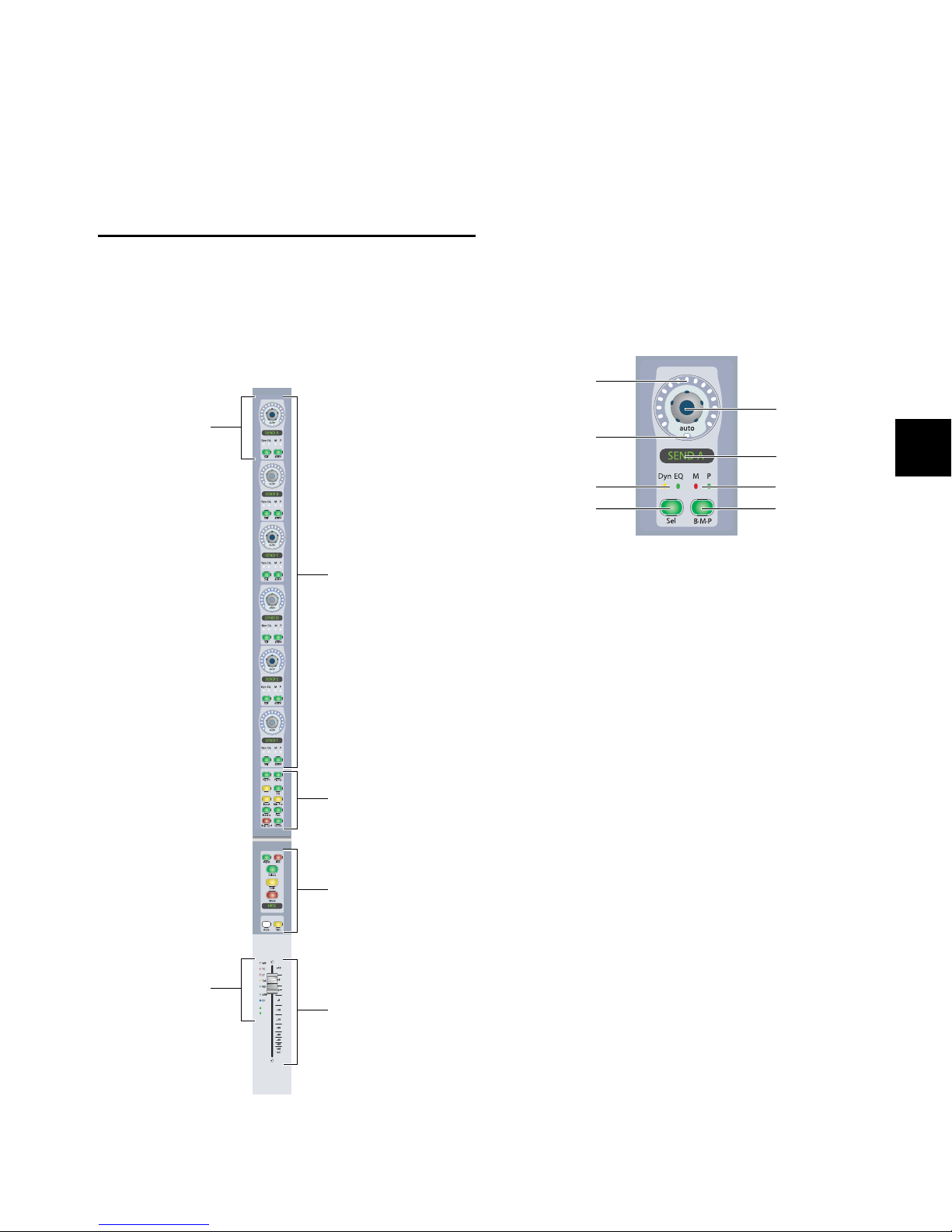
Chapter 6: Channel Strip Controls
Rotary EncoderRotary Encoder
Channel Strip
Channel Strip
Channel Fader
Mode controls
Function controls
section
Automation Mode
and
Channel Status
indicators
Rotary Encoder
Encoder
LED Ring
Encoder Knob
Encoder Display
Mute/Pre indicators
Bypass/Mute/Pre
switch
Encoder
Automation Mode
indicator
Dynamics/EQ
Plug-in indicators
Select switch
Channel Strips
The D-Control Main Unit has one central channel strip, called
the Focus Channel Strip, and each D-Control Fader Module has
16 channel strips. Each channel strip (Figure 1) has identical
controls, including six touch-sensitive rotary encoders, display and mode controls, and a touch-sensitive fader.
Rotary Encoder Section
Each channel strip has six touch-sensitive rotary encoders
with LED ring, display, mode switches, and status indicators.
Rotary encoders control channel input, insert, send, pan, and
mic pre parameters.
Channel Strip Rotary Encoder
Encoder Knob
The encoder knobs on D-Control channel strips are
touch-sensitive. When you touch the encoder, the encoder
display switches from the parameter name to the parameter
value. Touch display of parameter values can be turned off.
Dyn
Figure 1. D-Control Channel Strip
When you are automating a parameter controlled by an encoder, touching the encoder knob starts writing automation.
Inputs, Outputs, Inserts and Sends
When assigning a channel input or output, or an insert or
send, the encoder knob is used to scroll through available inputs, outputs, inserts, or sends. When adjusting the phantom
power on a remote-controlled mic preamplifier (such as the
Digidesign PRE), the encoder knob can be used to toggle phantom power on and off.
Instrument Tracks
On Instrument tracks, the bottom encoder knob is used to
control MIDI Volume.
VCA Master Tracks
On VCA Master tracks, the encoder knobs are used to control
the Volume of slave tracks.
Chapter 6: Channel Strip Controls 49
Page 58

Encoder LED Ring
Dynamics and EQ Plug-in Indicators
Each encoder has a ring of 15 three-color LEDs. Discrete or
stepped information is shown by single LEDs, and continuously variable information is shown by an expanding series of
LEDs.
In Normal mode, encoder LED rings can show send level, pan
position, plug-in parameter values, and mic pre settings. In
Flip mode, they show track level.
Instrument Tracks
On Instrument tracks, the bottom encoder LED ring shows
MIDI Velocity.
VCA Master Tracks
On VCA Master tracks, encoder LED rings show levels of slave
tracks.
Encoder Automation Mode Indicator
Below each encoder knob is an LED marked “auto,” which
lights when the corresponding parameter is enabled for automation. The indicator lights green for Read mode, solid yellow
when armed for automation in any of the Write modes, and
flashes red when writing automation in any of the Write
modes.
When viewing inserts on an encoder, these LEDs light to indicate the presence of a Dynamics plug-in (yellow LED) or EQ
plug-in (green LED).
Mute and Pre Indicators
When viewing sends on an encoder, these LEDs light to indicate that the send is muted (red LED) or set to pre-fader operation (green LED).
Encoder Select Switch
Each encoder has a Select switch that is used to assign an insert or send to that encoder, or to display insert or send
parameters for editing.
Inserts
When assigning an insert, the encoder Select switch is used to
confirm the selection of the following elements on each level:
• Insert type (TDM plug-in, RTAS plug-in, Multi-Mono
TDM plug-in, Multi-Mono RTAS plug-in, or Hardware
Insert)
• Plug-in subfolder (such as EQ, Dynamics, Pitch Shift,
Reverb, or Delay)
• Individual insert or plug-in
Encoder Display
Each encoder has a six-character display that shows parameter
names. When the corresponding encoder knob is touched or
moved, the display shows parameter values.
Encoder displays use colors and backlighting to indicate the
following:
• Green: Default color for input, insert, send, pan, and mic
pre parameter names and values
• Inverted green: Inactive input, inactive output, inactive
plug-in or inactive send names
• Yellow: Assignment options in Assign mode, any parameters in Flip mode
• Red: Clipped plug-in, send or channel
When viewing a plug-in, the encoder Select switch is used to
display and edit plug-in parameters on that channel’s rotary
encoders.
Sends
When assigning a send, the encoder Select switch is used to
confirm the selection of the following:
• Send type (interface or bus)
• Send assignment
When viewing a send, the encoder Select switch is used to display and edit send pan information on that channel’s rotary
encoders.
VCA Master Tracks
On VCA Master tracks, encoder Select switches focus the corresponding slave tracks in the Focus Channel Strip.
D-Control Guide50
Page 59

Bypass/Mute/Pre Switch
MIDI Controls on Instrument Tracks
Each encoder has a Bypass/Mute/Pre (B/M/P) switch whose
function depends on what is currently displayed on the encoder. With Sends, the function of the B/M/P switch also depends on the current Switch Mode setting.
See “Switch Mode Switch” on page 61 for more information
on changing the Switch mode and viewing the current function of the B/M/P switch.
Inserts
When a plug-in name is displayed on an encoder (in the top
level Inserts display), the B/M/P switch bypasses the corresponding plug-in. The B/M/P switch lights when the plug-in is
bypassed.
When a plug-in parameter is displayed on an encoder (by
pressing its Select switch) the B/M/P switch affects certain parameters (such as polarity or channel linking) that can be toggled on and off.
Sends
When a send name is displayed on an encoder, the B/M/P
switch does one of the following:
• If the Switch Mode is set to Mute, the B/M/P switch
mutes the corresponding send. The red Mute LED lights
to indicate that the send is muted.
• If the Switch Mode is set to Pre, the B/M/P switch toggles
the corresponding send between pre- and post-fader operation. The green Pre LED lights to indicate that the
send is set for pre-fader operation.
Mic Pre
When mic pre parameters are displayed on a channel strip’s
encoders (in the top level Mic Pre display), the B/M/P switches
do the following:
• Top encoder B/M/P: toggles phantom power on and off
• Gain encoder B/M/P: toggles mic pre HPF on and off
• Source encoder B/M/P: toggles mic pre Insert on and off
• Pad encoder B/M/P: toggles mic pre Pad on and off
• Polarity encoder B/M/P: toggles mic pre Polarity
The Instruments View in Pro Tools contains MIDI controls
that can be displayed on the bottom encoder of D-Control
channel strips.
To display MIDI volume and mute controls on an Instrument
track:
Press the Input switch in the Channel Strip Mode controls
section of the Instrument channel strip.
The MIDI controls appear on the bottom encoder (Encoder 6)
as follows:
• Encoder knob: MIDI Volume
• B/M/P switch: MIDI Mute
• Encoder LED ring: MIDI Velocity meter
To display MIDI pan controls:
Hold the Input switch and press the Pan switch in the Chan-
nel Strip Mode controls section of the channel strip.
The bottom encoder (Encoder 6) knob controls MIDI Pan.
To exit display of MIDI controls:
Press another switch in the Channel Strip Mode section.
Slave Track Display on VCA Master Tracks
In normal Mode, VCA Master tracks show their slave tracks in
their rotary encoders, as follows:
• Encoder knob: Slave track Volume control
• Encoder LED ring: Slave track meter level
• Encoder B/M/P switch: Slave track mute
• Encoder Select switch: Focuses slave track in Focus Channel Strip
If there are more than six slave tracks for a VCA Master, you
can the press the channel Page Up/Page Down switches to display the additional slave tracks on the rotary encoders.
Instrument Tracks
On Instrument Tracks, the bottom B/M/P switch is used to
control MIDI Mute state.
VCA Master Tracks
On VCA Master tracks, B/M/P switches are used to control the
Mute state of slave tracks.
Chapter 6: Channel Strip Controls 51
Page 60

Channel Strip Mode Controls
Page Up switch
Dynamics switch
Microphone
Preamplifier switch
Inserts switch Pan switch
Bypass/Spill
switch
Sends switch
Input switch
EQ switch
Page Down switch
Input Switch
Each channel strip has a set of Channel Strip Mode controls
for displaying and editing pan, plug-in, mic pre, insert, or
send parameters on the encoder section of the D-Control
channel strip.
Channel Strip Mode controls
Page Up and Page Down Switches
Control parameters are arranged on channel strip rotary encoders in pages, or groups of up to six parameters at a time.
The Page Up and Page Down switches light to indicate the
presence of additional pages of sends, pan, plug-in, mic pre
parameters, or (for VCA Master tracks) slave tracks, in the corresponding direction on each channel strip. If no additional
pages are available, neither switch is lit.
With Audio and Auxiliary Input tracks, the Input switch is
used to put channels into Inline mode. See “Inline Console
Mode” on page 135.
With Instrument tracks, the Input switch is used to display
that track’s MIDI controls on the rotary encoders. See “MIDI
Controls on Instrument Tracks” on page 51.
Mic Pre Switch
When you press the Mic Pre switch, the controls for an available remote-controlled microphone preamplifier (such as the
Digidesign PRE) are displayed on the channel strip’s rotary encoders for editing. Microphone preamplifiers are declared in
the Pro Tools Peripherals dialog, and assigned to channels in
the Pro Tools I/O Setup dialog.
Inserts Switch
When you press the Inserts switch on a channel strip, plug-in
names are shown in two groups of five (Inserts A–E or Inserts
F–J) on the encoder displays.
You can use Flip mode to transfer controls for any insert (A–J)
from the channel encoders to the Faders. See “Flip Mode” on
page 133.
To move the page display of parameters on the encoders up or
down:
Press a lit Page Up or Page Down switch.
Dynamics and EQ Switches
The Dynamics and EQ switches light to indicate the presence
of the corresponding type of plug-in on a channel strip.
To display a channel strip’s first Dynamics or EQ plug-in on the
rotary encoders for editing:
Press a lit Dynamics or EQ switch.
To cycle through all the Dynamics or EQ plug-ins on a channel:
Repeatedly press the corresponding switch.
To toggle display of Inserts A–E and F–J on a channel strip:
1 Press the Inserts switch in the Channel Strip Mode controls
section of the channel strip to show the top level Insert display.
2 Press the Pag e Up and Page Down switches to toggle the t op
level Send display between the two sets of five sends (A–E and
F–J).
To view the parameters for an individual plug-in:
Press the Select switch on the corresponding encoder.
To return to the top level display of plug-ins on the channel strip:
Press the Inserts switch again.
The Inserts switch flashes when a plug-in on that channel has
clipped. To clear a clip, press the Clear Clip switch in the Session Management section. See “Clear Clip Switch and Plug-in
Clip Indicator” on page 102 for more information.
D-Control Guide52
Page 61

Pan Switch
Bypass/Spill Switch
When you press the Pan switch, the pan controls for the channel strip are displayed on the encoder displays.
If the track is a multichannel track, its Page Up switch lights to
indicate that there are multiple pages of pan controls. Multichannel pan controls are arranged as follows:
Surround Pan Display, Page 1
Display Pan Control
LFE LFE channel
Cntr% Center Speaker Percentage
F Div Front Divergence
Rear Rear Pan
F/R Front/Rear Balance
Front Front Pan
Surround Pan Display, Page 2
Display Pan Control
R Div Rear Divergence
Rear Rear Pan
F/R Div Front/Rear Divergence
F/R Front/Rear Balance
F Div Front Divergence
Front Front Pan
To open/close the Output window on-screen for a track:
1 Press the Pan switch on the channel.
2 Hold Start (Windows) or Control (Mac) and press the chan-
nel’s encoder switch.
Two-Knob Surround Panning
When working in surround, you can link the front and rear
pan controls on D-Control to facilitate X-axis motion in the
sound field.
To link front and rear surround panners:
1 Press the Operation switch in Console Prefs section until
“2KbPan” appears in the Soft Keys.
The function of the Bypass/Spill switch depends on what is
currently displayed on the channel strip.
Inserts
In the top level Inserts view (when plug-in names are dis-
played on a channel strip’s encoders), the Bypass/Spill switch
bypasses all plug-ins on that channel.
When a single plug-in’s parameters are displayed on a chan-
nels strip’s encoders, the Bypass/Spill switch bypasses that
plug-in only.
Sends
In the top level Sends view (when send names are displayed
on a channel strip’s encoders), the Bypass/Spill switch mutes
all sends on that channel.
When a single send’s parameters are displayed on a chan-
nels strip’s encoders, the Bypass/Spill switch has no effect.
VCA Master Tracks
On VCA Master tracks, the Bypass/Spill switch displays (or
“spills”) the slave tracks for the VCA in Custom Faders.
Sends Switch
When you press the Sends switch on a channel strip, sends are
shown in two groups of five (Sends A–E or Sends F–J) on the
encoder displays. The rotary encoders control Send level.
You can use Flip mode to transfer controls for any send position (A–J) to the Faders. See “Flip Mode” on page 133.
To toggle display of Sends A–E and F–J on a channel strip:
1 Press the Sends switch in the Channel Strip Mode controls
section of the channel strip to show the top level Send display.
2 Press the Pag e Up and Page Down switches to toggle the t op
level Send display between the two sets of five sends (A–E and
F–J).
To open/close a Send window on-screen:
1 Press the Sends switch on the channel whose Send window
you want to open/close.
2 Hold Start (Windows) or Control (Mac) and press the en-
coder Select switch for the Send you want to open/close.
2 Press the Soft Key that corresponds to “2KbPan” to toggle
the preference on or off.
Chapter 6: Channel Strip Controls 53
Page 62

Send Pan Mode
Input Monitor Mode
switch
Channel Select
switch
Solo switch
Mute switch
Channel display
Automation Mode
switch
Record Enable
Automation Trim
switch
switch
Send Pan mode allows you to adjust panning and level for an
individual send on a channel at the same time. In Send Pan
mode, Send Level is controlled by the channel fader and Send
Pan is controlled by the encoders.
Send Pan mode lets you view different sends on individual
channels, or by using the Do To All or Do To Selected
switches, the same send across multiple channels.
In Send Pan mode, you can link Pan controls of individual
Sends to the Main Pan controls of their tracks (the “Follow
Main Pan” or “FMP”).
To enter Send Pan mode:
1 Press the Sends switch to display sends on the channel’s en-
coders.
2 Press the encoder Select switch that corresponds to the send
you want to display. The channel’s Send and Pan switches
light to indicate that it is in Send/Pan mode.
Channel Strip Function Controls
Each channel strip has a set of Channel Strip Function controls for controlling channel selection and focus, mute, solo,
and record enable status, input monitor mode, and automation mode.
Channel Strip Function controls
To return to the top level display of sends on the channel strip:
Press the Sends switch again.
To link a Send’s Pan controls to the Main Pan controls of a track:
1 Put the track in Send Pan mode for the Send you want to
link.
2 Press the B/M/P switch on any of the active encoders on the
track to toggle the FMP status of the send.
Send Clipping Indication
The Sends switch flashes when a send on that channel has
clipped. To clear a clip, press the Clear Clip button in the Session Management section. See “Clear Clip Switch and Plug-in
Clip Indicator” on page 102 for more information.
D-Control Guide54
Input Monitor Mode Switch
The Input Monitor Mode switch toggles the input monitoring
mode for that channel between Auto Input and Input Only
mode. The switch lights when the channel is in Input Only
mode.
Record Enable Switch
The Record Enable switch toggles record enable status for the
channel. When the channel is record-enabled and the
Pro Tools transport is stopped, the switch flashes. During recording, the switch lights continuously.
Record Safe Mode To record safe a track from D-Control, hold
Control (Windows) or Command (Mac) and press the track’s
Record Enable switch.
Channel Select Switch
The function of the Channel Select switch depends on the Select/Focus Mode setting. See “Select/Focus Mode Switch and
Indicators” on page 67 for more information on changing the
Select/Focus mode.
Select Mode If the Select/Focus Mode is set to Select, the
Channel Select switch selects the channel in Pro Tools. The
switch lights when the channel is selected. In this mode, the
Channel Select switch can be set to follow latching or exclusive-or (non-latching) behavior.
Focus Mode If the Select/Focus Mode is set to Focus, the Channel Select switch focuses that channel’s controls on the Focus
Channel Strip on the Main Unit. The switch lights when the
channel is focused. In this mode, because only one track can
be focused at a time, the Select switch follows exclusive-or
(non-latching) behavior only.
Page 63

Solo Switch
Automation Mode Switch
The Solo switch toggles solo status for the channel. When a
channel is soloed, the Solo switch lights, and the Mute
switches on other channels in the session flash to indicate implicit mute. The Solo switch function follows the Pro Tools
Operation preference for latched operation.
Solo Safe Mode To solo safe a track, hold Control (Windows)
or Command (Mac) and press the track’s Solo switch.
When a track is solo safed, its Solo switch flashes once.
Mute Switch
The Mute switch toggles mute status for the channel.
When a track is muted, its Mute switch lights solid.
When a track is implicitly muted (when another track is so-
loed), its Mute switch flashes.
Channel Display
Each channel display shows the channel information in the
following display modes. In each mode, when the channel
fader is touched, the display shows the channel volume in dB.
Track Name Mode Shows the track name only.
Group/Name Mode Shows the group membership of the track
(by group letter) and an abbreviated track name.
The Automation Mode switch cycles the channel through the
Pro Tools automation modes (Write, Latch, Touch, Read and
Off). The active mode is shown by the Automation Mode LED
indicators to the left of each channel’s fader. When in Off
mode, none of the indicators is lit.
The Automation Mode switch lets you cycle the channel
through Touch, Latch, and Read modes during playback, but
it prevents you from entering Write or Off mode during playback. To directly enter Write or Off mode during playback, use
the Automation Mode controls in the lower left and right of
the Main Unit. (See “Automation Mode Controls” on
page 69.)
You can use the Do To All and Do To Selected switches to select automation modes across multiple channels.
To select an automation mode for a channel, do one of the
following:
• To cycle forward through the automation modes, press
the Automation Mode switch on the channel.
– or –
• To cycle backward through the automation modes, hold
Shift and press the Automation Mode switch on the
channel.
Automation Trim Switch
Track Position Number/Name Mode Shows the track position
number and an abbreviated track name.
Headroom Mode Shows the abbreviation “HR” followed by the
remaining headroom in dB.
Level Mode Shows the track volume level in dB only.
Channel displays use colors and backlighting to indicate the
following:
• Green: Channel names and values
• Inverted green: Inactive channel
• Red: Clipped channel
The Automation Trim switch toggles the channel into the corresponding Trim mode for Write, Latch, Touch, and Read
modes. Active Trim mode is shown by the yellow Trim mode
LED indicator to the left of each channel’s fader. The Automation Trim switch has no effect while the channel is in Off
mode.
Chapter 6: Channel Strip Controls 55
Page 64

Fader Section
Automation Mode
indicators
Group Status
indicator
Custom Fader Mode
indicator
AutoMatch
indicators
Channel
Fade r
Shift Control Win (Start) (Windows)
Option (Mac)
Alt (Windows)
a (Command) (Mac)
Channel Strip Fader section
Fader
The touch-sensitive faders on D-Control channel strips control channel volume in Normal mode, and a wide range of parameters in Flip mode or the Custom Fader modes. When you
touch a fader, its channel strip display changes from track
name to track volume level (in Normal mode), or from parameter name to parameter value (in Flip modes or Custom Fader
modes). When you are automating a parameter on a fader,
touching the fader starts writing automation.
Custom Fader Mode Indicator
The Custom Fader Mode indicator (a blue LED marked CF), located to the left of each channel’s fader, lights to indicate that
the channel is currently in Custom Fader Mode.
AutoMatch Indicators
The AutoMatch indicators (green arrow-shaped LEDs), located
to the left of each channel’s fader, light to indicate the direction you need to move the fader in order to match the automation level previously written for that track. This is especially useful when editing fader automation.
Modifier Key Switches
Each D-Control Fader Module has a set of four switches in its
lower left corner that duplicate the function of the Pro Tools
computer keyboard modifiers.
Modifier Keys (Fader Module)
Automation Mode Indicators
The Automation Mode indicators, located to the left of each
channel’s fader, indicate the active automation mode.
WR (Write), TC (Touch) and LT (Latch) are red LEDs; TM
(Trim) is a yellow LED; and RD (Read) is a green LED.
When in Write mode, the Write indicator flashes at all
times.
When in Touch or Latch modes, the corresponding indica-
tor lights solid until automation writing begins.
When a track in Latch mode is primed for writing automa-
tion, its Latch mode indicator flashes.
When automation writing begins, the appropriate indicator
flashes.
If automation is turned off for the channel (Off), none of
the indicators is lit.
Group Status Indicator
The Group Status indicator (a green LED marked GRP), located
to the left of each channel’s fader, lights to indicate that the
channel is a member of an active Mix or Edit group in
Pro Tools. If the channel is a member of an inactive group, or
if groups are suspended, this indicator is off.
Shift Switch (Windows and Mac)
The Shift switch duplicates the function of the Shift key on
the D-Control computer keyboard.
Control Switch (Windows and Mac)
The Control switch duplicates the function of the Control key
on the D-Control computer keyboard.
Win Switch (Windows) or Option Switch (Mac)
The Win/Option switch duplicates the function of the Windows (Start) key (Windows) or the Option key (Mac) on the
D-Control computer keyboard.
Alt Switch (Windows) or Command Switch (Mac)
The Alt/Command switch duplicates the function of the Alt
key (Windows) or the Command key (Mac) on the D-Control
computer keyboard.
The order of the modifier keys on the Fader Module
reflects the order of the corresponding keys on a
Windows or Mac keyboard, from left to right.
D-Control Guide56
Page 65
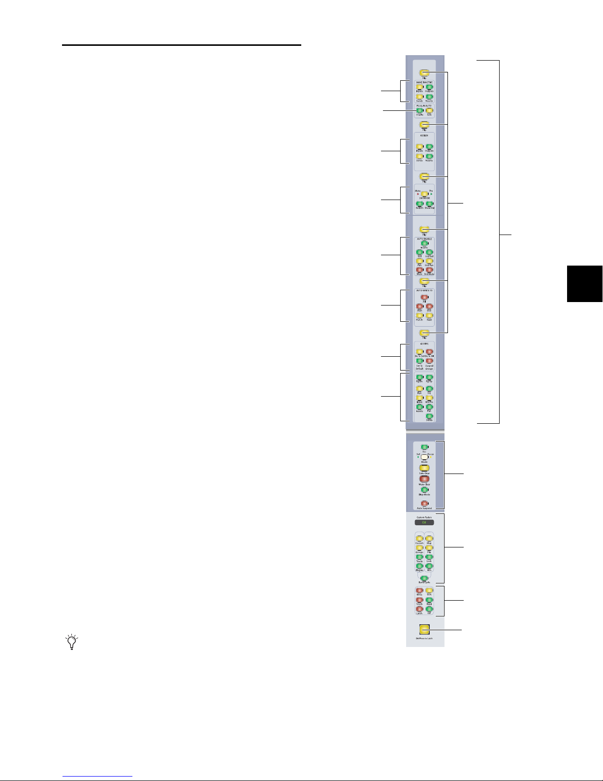
Channel
Strip Master
Function controls
Custom Fader
controls
Talkback switch
Automation Mode
controls
Make Inactive
controls
Plug-in Automation
controls
Assignment
controls
Switch Information
controls
Automation Enable
controls
Automation Write
controls
Global
controls
Global
Channel Strip
Mode controls
Flip
switches
Channel
Strip Master
Assign and
Display
controls
Channel Strip Master Section
The Channel Strip Master section (Figure 2) is a set of channel-related controls that appears on both the left and right
sides of the D-Control Main Unit, allowing easy access to
these controls from any mixing position. The operation of
each control in this section is mirrored on both sets of controls at all times.
Flip Switches
The six yellow Flip switches in the Channel Strip Master section correspond to the six horizontal rows of rotary encoders
on the D-Control channel strips.
Flip Mode
The Flip switches invoke Flip mode, which transfers controls
from the corresponding rotary encoder to the fader on each
channel strip, allowing convenient editing and automation of
send, pan, plug-in, and mic pre parameters directly from the
channel faders.
In Flip mode, the rotary encoder control swaps with the channel fader; the encoder Select switch swaps with the channel
Select switch; the encoder Bypass/Mute/Pre switch swaps with
the channel Mute switch; and the encoder display swaps with
the channel display.
In Flip mode, the Flip switch for the affected row of encoders
is lit, and the affected encoder displays appear in yellow.
Instrument Tracks and Flip Mode
In Flip mode, Instrument track controls are transferred as follows:
• The fader on each channel controls the parameter (MIDI
Volume or MIDI Pan) that was assigned to the bottom encoder, and the bottom encoder controls track Volume.
• The channel Mute switch controls the MIDI Mute function,
and the B/M/P switch on the bottom encoder controls
channel mute.
To transfer controls from a row of rotary encoders to the channel
faders:
Press the Flip switch that corresponds to the encoder row.
To exit Flip mode:
Press a lighted Flip switch.
When D-Control is in Flip mode and you enter Make
Inactive mode or Assign mode, it is temporarily taken
out of Flip mode, but the Flip switch remains lit.
When you exit Make Inactive mode or Assign mode,
controls return to their flipped positions.
Figure 2. Channel Strip Master section
Chapter 6: Channel Strip Controls 57
Page 66

Flop Mode
Inputs Inactive
switch
Sends Inactive
switch
Outputs Inactive
switch
Inserts Inactive
switch
Inputs Inactive Switch
A variation of Flip mode, Flop mode transfers controls from
any of the top five rows of rotary encoders to the bottom row
of rotary encoders, allowing you to bring any encoder control
within easy reach from the mix position.
In Flop mode, the affected row of encoders moves to the bottom row of encoders, the Flip switches for both affected rows
are lit, and the encoder displays for both rows appear in yellow.
To transfer controls from any of the top five rows of encoders to
the bottom row of encoders:
Hold the Start key (Windows) or Control key (Mac) and
press the Flip switch that corresponds to the encoder row.
To exit Flop mode:
Press either of the lighted Flip switches.
Wh en D- Cont rol is in Make Inact ive m ode o r Ass ign mode,
it is temporarily taken out of Flop mode, but the Flip
switches remains lit. When you ex it M ake I nact ive m ode o r
Assign mode, controls return to their flopped positions.
Make Inactive Controls
The Inputs switch invokes Inputs Inactive mode and displays
channel inputs in the bottom row of encoders. The Bypass/Mute/Pre switch on the bottom encoder toggles the input inactive and active.
Outputs Inactive Switch
The Outputs switch invokes Outputs inactive mode and displays the main channel outputs in the bottom row of encoders. The Bypass/Mute/Pre switch on the bottom encoder toggles the output inactive and active.
Sends Inactive Switch
The Sends switch invokes Sends Inactive mode and displays
the channel’s sends on its encoders. The Bypass/Mute/Pre
switch on each encoder toggles the corresponding send inactive and active.
Inserts Inactive Switch
The Inserts switch invokes Inserts Inactive mode and displays
a channel’s inserts on its encoders. The Bypass/Mute/Pre
switch on each encoder toggles the corresponding insert inactive and active.
The Make Inactive controls are used to make tracks, inputs,
outputs, sends, or inserts inactive. Each switch puts D-Control
into a temporary Make Inactive mode in which elements are
made inactive or reactivated. The switch flashes while Make
Inactive mode is in effect.
Make Inactive Controls
Making a Track Inactive
In Make Inactive mode, channel Select switches are lit on all
tracks.
To toggle a track inactive/active:
1 Press any of the Make Inactive switches.
2 Press the channel strip Select switch for each track you want
to deactivate or activate.
3 Press the flashing Make Inactive switch to exit Inactive
mode.
To toggle an input, output, send, or insert active/inactive:
1 Make sure the channel is showing the top-level view for the
element you want to make active/inactive.
2 Press a Make Inactive switch to enter the appropriate Make
Inactive mode.
3 Press the Bypass/Mute/Pre switches on encoders to deacti-
vate or reactivate their corresponding track elements.
4 Press the flashing Make Inactive switch to exit Inactive
mode.
D-Control Guide58
Page 67

Plug-in Automation Controls
Enable Parameter
switch
Automation Safe
switch
Assign Inputs
switch
Assign Sends
switch
Assign Outputs
switch
Assign Inserts
switch
The Plug-in Automation controls are used to enable parameters for automation and to place them in automation safe
mode.
To toggle automation safe on and off:
1 Press the Automation Safe switch.
2 Press the channel Select switch on the tracks for which you
want to toggle automation safe status. The automation safe
status of the track is reflected by the Safe button in the track’s
on-screen output window.
3 Press the Bypass/Mute/Pre switch for the plug-ins or sends
for which you want to toggle automation safe status.
Plug-in Automation controls
Enable Parameters Switch
The Enable Parameters switch lets you enable parameters for
automation by touching or pressing their controls.
In Enable Parameters mode, the Enable Parameters switch is
lit. While in this mode, the Auto LED for any rotary encoder
enabled for automation is lit red, and the switch for any parameter enabled for automation is lit.
To toggle automation on and off for plug-in parameters:
1 Press the Enable Parameters switch.
2 Touch the rotary encoders or press the switches for the con-
trols whose automation you want to toggle on or off.
3 Press the Enable Parameters switch again to exit Enable Pa-
rameters mode.
You can also toggle automation for a plug-in parameter by
holding Control+Alt+Start (Windows) or Command+Option+Control (Mac) and touching the rotary encoder for the
parameter.
Automation Safe Switch
4 Press the Automation Safe switch again to exit Automation
Safe mode.
Assign Controls
The Assign controls are used to assign inputs, outputs, inserts,
and sends to channels. Each switch puts D-Control into a temporary Assign mode in which elements are assigned or removed from channels. The switch flashes while Assign mode
is in effect.
You can enter Assign mode while Pro Tools is playing back. To
confirm the assignment of inputs, outputs, and sends, the
transport must be stopped. You can, however, confirm the assignment of inserts during playback.
The Automation Safe switch invokes a mode in which the Bypass/Mute/Pre switch for each plug-in or send and the channel Select switch for each track become Safe switches.
Plug-ins and Sends
While in Automation Safe mode, pressing a Bypass/Mute/Pre
switch on a plug-in or send protects any automation on that
plug-in or send from being overwritten. The Bypass/Mute/Pre
switch for any protected plug-in or send is lit, reflecting the
state of the Safe button in the on-screen plug-in or send output window.
Tracks
While in Automation Safe mode, pressing a channel Select
switch protects volume, pan and mute parameters on that
track from being overwritten. The channel Select switch for
any protected track is lit, reflecting the state of the Safe button
in the on-screen track output window.
Assignment controls
Assign Inputs Switch
The Inputs switch invokes Assign Inputs mode, in which the
bottom row of encoders shows channel inputs.
When assigning an input, the Select switch on the bottom encoder is used to navigate down through Input menu levels,
and the encoder knob is used to scroll through available
choices at each level:
• Input type (Interface or Bus), shown in yellow
• Individual inputs, shown in green
Press the Bypass/Mute/Pre switch on the bottom encoder to
navigate back up the Input menu levels.
Chapter 6: Channel Strip Controls 59
Page 68

Assign Outputs Switch
The Outputs switch invokes Assign Outputs mode, in which
the bottom row of encoders shows channel outputs.
When assigning an output, the Select switch on the bottom
encoder is used to navigate down through Output menu levels, and the encoder knob is used to scroll through available
choices at each level:
• Output type (Interface or Bus), shown in yellow
• Individual outputs, shown in green
Press the Bypass/Mute/Pre switch on the bottom encoder to
navigate back up the Output menu levels.
Assign Sends Switch
The Sends switch invokes Assign Sends mode, in which the
channel encoders shows the sends on a channel.
When assigning a send, the encoder Select switch is used to
navigate down through Send menu levels, and the encoder
knob is used to scroll through available choices at each level:
• Send type (Interface or Bus), shown in yellow
• Individual sends, shown in green
The Bypass/Mute/Pre switch on each encoder is used to navigate back up the Send menu levels.
Assign Inserts Switch
The Inserts switch invokes Assign Inserts mode, in which the
channel encoders show the inserts on a channel. When assigning an insert, the encoder Select switch is used to navigate
down through Insert menu levels, and the encoder knob is
used to scroll through available choices. The Bypass/Mute/Pre
switch on the bottom encoder is used to navigate back up the
Insert menu levels.
The order in which plug-ins appear in the Insert menu is determined by the Pro Tools Display preference for plug-in organization.
If the Organize Plug-in Menus by Category option is selected,
menu levels and choices include:
• Insert type (TDM plug-in, RTAS plug-in, Multi-Mono
TDM plug-in, Multi-Mono RTAS plug-in, or Hardware Insert), shown in yellow
• Plug-in subfolder (such as EQ, Dynamics, Pitch Shift, Reverb, and Delay), shown in yellow
• Individual insert or plug-in, shown in green
To assign an input, output, send or insert:
1 Press an Assign switch to enter the corresponding Assign
mode.
2 On the channel where you want to make the assignment,
turn an encoder knob to select from the first level of menu
choices.
3 Press the encoder Select switch to move down and the By-
pass/Mute/Pre switch to move up through menu levels.
4 Do one of the following:
• Press the flashing encoder Select switch or press the flashing Assign switch to confirm the assignment.
– or –
• Press the flashing Escape switch to cancel the assignment.
To assign multiple inputs, outputs, sends, or inserts:
1 Press an Assign switch to enter the corresponding Assign
mode.
2 Turn the encoder knobs and use the encoder Select and By-
pass/Mute/Pre switches to select each assignment.
3 Do one of the following:
• Press the flashing Assign switch to confirm all the assignments at once.
– or –
• Press the flashing Escape switch to cancel all the assignments.
To remove an input, output, send or insert:
1 Press an Assign switch to enter the corresponding Assign
mode.
2 For the assignment you want to remove, press the encoder
Bypass/Mute/Pre switch repeatedly until you reach top level
menu for the assignment.
3 Turn the encoder knob counter-clockwise until no assign-
ment is visible.
4 Do one of the following:
• Press the flashing encoder Select switch or press the flashing Assign switch to confirm the removal.
– or –
• Press the flashing Escape switch to cancel the removal
and restore the assignment.
If the Organize Plug-in Menus by Category option is not selected, the Plug-in subfolder level is not present.
D-Control Guide60
Page 69

Removing Plug-in Assignments
Show ValuesSwitch Info
Switch Mode switch
switch switch
Pre-Fader Mode
indicator
Mute Mode
indicator
Switch Information Controls
You can use the Set to Default switch to quickly remove
plug-in assignments from tracks, without having to go into
Assign mode.
This method removes the assignments immediately,
and cannot be canceled.
To quickly remove plug-in assignments:
1 Press the Set to Default switch.
2 Press the encoder Select switch for each plug-in assignment
you want to remove.
3 Press the flashing Set to Default switch.
Assigning MIDI Inputs and Outputs on Instrument
Tra cks
The Assign Inputs and Assign Outputs switches can be used to
assign the MIDI Inputs and Outputs on Instrument tracks.
To assign a MIDI Input or Output on an Instrument track:
1 Press the Assign Inputs or Assign Outputs switch to enter the
corresponding Assign mode. Encoder row #5 shows MIDI inputs/outputs.
2 On each channel where you want to make an assignment,
turn the encoder knob in encoder row #5 to select from the
first level of MIDI menu choices.
3 Press the encoder’s Select switch to move down and the By-
pass/Mute/Pre switch to move up through MIDI menu levels.
The Switch Information controls are used to change the mode
and display of encoder Bypass/Mute/Pre switches, and globally show encoder parameter values.
Switch Information controls
Switch Mode Switch
The Switch Mode switch toggles the function of encoder Bypass/Mute/Pre switches between Mute and Pre-Fader functions when displaying sends on the encoders.
• When the Switch Mode is set to Bypass, the encoder B/M/P
switch mutes the corresponding send.
• When the Switch Mode is set to Pre, the encoder B/M/P
switch toggles the corresponding send between pre- or
post-fader operation.
To set the Switch Mode:
Press the Switch mode switch repeatedly until the appropri-
ate indicator lights (Mute or Pre).
4 Do one of the following:
• Press the flashing encoder Select switch or press the flashing Assign switch to confirm the assignments.
– or –
• Press the flashing Escape switch to cancel the assignments.
Switch Info Switch
The Switch Info switch can follow toggling or momentary behavior. If pressed briefly, it toggles the encoder display to
show the function assigned to the Bypass/Mute/Pre switch on
each rotary encoder. If held, the function is shown until the
switch is released.
Show Values Switch
The Show Values switch can follow toggling or momentary
behavior. If pressed briefly, it toggles encoder display between
parameter name and parameter value. If held, parameter value
is shown until the switch is released.
Chapter 6: Channel Strip Controls 61
Page 70

Automation Enable Controls
Enable Inserts
Automation
Enable Send Volume
Automation
Enable Send Mute
Automation
Enable Volume
Automation
Enable Pan
Automation
Enable Mute
Automation
Enable Send Pan
Automation
switch
switch
switch
switch
switch
switch
switch
Automation
Write to All
Automation
Write to End
Automation
Write to Start
Automation
Write to Punch
Automation
Write to Next
switch
switch
switch
switch
switch
Send Mute Switch
The Automation Enable controls are used to enable or suspend
writing of each type of automation on all channels. The Automation Enable controls mirror the function of the corresponding buttons in the Automation Enable window.
When writing is enabled for an automation type but it is not
currently writing on any track in the session, the corresponding switch lights solid.
When writing is enabled for an automation type and it is
currently writing on any track in the session, the corresponding switch flashes.
Automation Enable controls
Inserts Switch
The Inserts switch enables and suspends writing of automation for any automation-enabled plug-in parameters on all
tracks in the session.
Volume Switch
The Volume switch enables and suspends writing of channel
volume automation on all tracks in the session.
The Send Mute switch enables and suspends writing of send
mute automation on all channels.
Automation Write To Controls
The Auto Write To controls invoke the manual “Write to
Start/End/All/Punch/Next” commands and the automatic
“Write to Start/End/All/Punch/Next on Stop” automation
commands in Pro Tools.
The “Write to Start/End/All/Punch/Next” commands can also
be invoked from the Soft Keys section of D-Control.
“Auto Write To” switches
All Switch
The All switch writes the current automation value of all
write-enabled parameters to an entire selection or track when
performing an automation pass.
To manually write automation to all of a track or selection:
Press the All switch during playback.
Pan Switch
The Pan switch enables and suspends writing of channel pan
automation on all tracks in the session.
Mute Switch
The Mute switch enables and suspends writing of channel
mute automation on all tracks in the session.
Send Volume Switch
The Send Volume switch enables and suspends writing of send
volume automation on all tracks in the session.
Send Pan Switch
The Send Pan switch enables and suspends writing of send
pan automation on all tracks in the session.
D-Control Guide62
To write automation to all of a track or selection on stop:
Hold the Start key (Windows) or the Control key (Mac) and
press the All switch.
To set Write to All on Stop to remain enabled after each
automation pass:
Hold the Alt+Start keys (Windows) or the Option+Control
keys (Mac) and press the All switch.
To disable automatic Write to All on Stop:
Press the flashing All switch.
Page 71

Start Switch
Punch Switch
The Start switch writes the current automation value of all
write-enabled parameters to the start of a selection or track
when performing an automation pass.
To manually write automation to the start of a track or selection:
Press the Start switch during playback.
To write automation to the start of a track or selection on stop:
Hold the Start key (Windows) or the Control key (Mac) and
press the Start switch.
To set Write to Start on Stop to remain enabled after each
automation pass:
Hold the Alt+Start keys (Windows) or the Option+Control
keys (Mac) and press the Start switch.
To disable Write to Start on Stop:
Press the flashing Start switch.
End Switch
The End switch writes the current automation value of all
write-enabled parameters to the end of a selection or track
when performing an automation pass.
The Punch switch writes the current automation value of all
write-enabled parameters back to the punch point (the location in the track where the current automation pass started).
To manually write automation back to the punch point:
Press the Punch switch during playback.
To write automation back to the punch point on stop:
Hold the Start key (Windows) or the Control key (Mac) and
press the Punch switch.
To set Write to Punch on Stop to remain enabled after each
automation pass:
Hold the Alt+Start keys (Windows) or the Option+Control
keys (Mac) and press the Punch switch.
To disable automatic Write to Punch on Stop:
Press the flashing Punch switch.
Next Switch
The Next switch writes the current automation value of all
write-enabled parameters forward to the next automation
breakpoint.
To manually write automation to the end of a track or selection:
Press the End switch during playback.
To write automation to the end of a track or selection on stop:
Hold the Start key (Windows) or the Control key (Mac) and
press the End switch.
To set Write to End on Stop to remain enabled after each
automation pass:
Hold the Alt+Start keys (Windows) or the Option+Control
keys (Mac) and press the End switch.
To disable automatic Write to End on Stop:
Press the flashing End switch.
Unlike the other Write To commands, the Write to Next on
Stop command always remains enabled after each automation
pass, until you disable it.
To manually write automation forward to the next breakpoint:
Press the Next switch during playback.
To set Write to Next on Stop to remain enabled after each
automation pass:
Hold the Start key (Windows) or the Control key (Mac) and
press the Next switch.
To disable automatic Write to Next on Stop:
Press the flashing Next switch.
Chapter 6: Channel Strip Controls 63
Page 72

Global Controls
Do to Selected
Set to Default
Do to All switch
Suspend Groups
switch
switch
switch
The Global controls are used to apply commands that affect
multiple channels in various ways.
Global controls
Do To All and Do To Selected Switches
The Do To All and the Do To Selected switches on D-Control
can be used in two different ways: to apply actions to multiple
tracks in a Pro Tools session, and to change the display mode
of multiple channel strips on D-Control.
The Do To All and Do To Selected switches can follow momentary or latching behavior.
When single-pressed, their effect applies only to the next
operation.
When held, they apply to all operations carried out while
being held.
When double-pressed, they latch on and flash until pressed
a second time.
Applying Actions to Multiple Tracks in Pro Tools
The Do To All and Do To Selected switches are convenient for
performing tasks such as muting, soloing, assigning sends, or
assigning the same plug-in across multiple tracks in a session.
To apply actions to multiple tracks in a Pro Tools Session:
1 Do one of the following:
• Press the Do To All or the Do To Selected switch to apply
the action to one parameter.
– or –
• Double-press the Do To All or the Do To Selected switch
to latch the corresponding action and apply it to multiple parameters.
2 Press any of the following switches to apply the correspond-
ing action to all tracks or all selected tracks in the current session:
• Channel Mute switch
• Channel Solo switch
• Channel Solo Safe: Control (Windows) or Command
(Mac) + Solo switch
• Automation Mode switch
• Automation Trim switch
• Channel Select switch (in Select mode)
• Record Enable switch
• Record Safe: Control (Windows) or Command (Mac) +
Record Enable switch
• Input Monitor Mode switch
3 Depending on the current channel strip display mode, you
can apply the following across all tracks or all selected tracks
in the session:
• Mic Pre Controls: Polarity, Pad, Impedance, Source, Gain
• Send Pre/Post: B/M/P switch in Send Pre/Post mode
• Send Mute: B/M/P switch in Send Mute mode
• Plug-in Bypass: B/M/P switch in Inserts mode
4 You can also carry out any of the following tasks across all
tracks or all selected tracks in the session:
• Assigning Inputs, Outputs, Inserts and Sends
• Deactivating Inputs, Outputs, Inserts, Sends and Tracks
• Resetting controls with the Set to Default switch
• Changing panner linkage
• Changing panner editor choice
D-Control Guide64
5 When you are finished, if Do To all or Do To Selected are
latched on, press the flashing Do To All or Do To Selected
switch to exit the corresponding mode.
Page 73
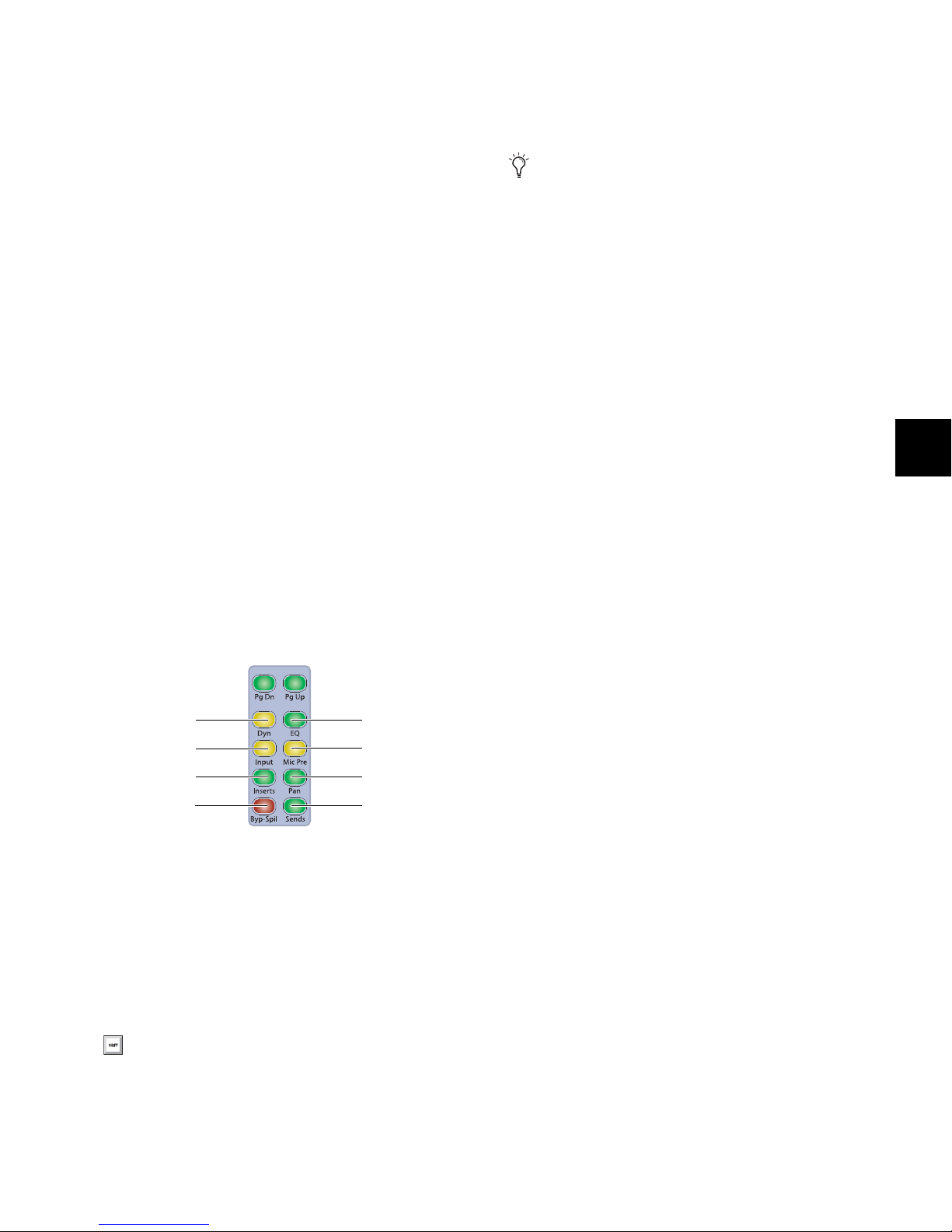
Changing Parameter Display on D-Control Channel Strips
Dynamics switch
Microphone
Preamplifier switch
Inserts switch Pan switch
Bypass/Spill
switch
Sends switch
Input switch
EQ switch
The Do To All and Do To Selected switches can be used to display and edit pan, mic pre, insert, or send parameters across all
tracks or all selected tracks in a session.
The Do To All and Do To Selected switches are applied independently to channel strips in Normal mode and channel
strips in Custom Fader mode. The display mode of the Focus
Channel Strip is not affected by Do To All or Do To Selected
operations.
The Set to Default switch can follow momentary or latching
behavior. When single-pressed, its effect applies only to the
next operation. When double-pressed, it latches on and
flashes until pressed a second time.
You can also use the Set to Default switch to remove
plug-in assignments from channels. See “Removing
Plug-in Assignments” on page 61.
While the Set to Default switch is pressed or latched on, the
following parameters can be reset:
This independent operation lets you put banks of channels in
several display modes at once (for example, pan on channels
in Normal mode, plug-ins on channels in Custom Fader
mode, and sends on the Focus Channel Strip).
To change the display mode of D-Control channel strips:
1 Press the Do To All or the Do To Selected switch.
2 Press any of the following Channel Strip Mode switches on
any individual channel to apply the corresponding action to
all or all selected channels on D-Control:
• Dynamics switch
•EQ switch
•Input switch
• Microphone Preamplifier switch
•Inserts switch
•Pan switch
• Bypass/Spill switch
•Sends switch
To reset a channel’s track volume to 0 dB:
Press the Set to Default switch + the channel Select switch.
– or –
Hold Alt (Windows) or Option (Mac) and touch the channel
fader.
To reset a channel’s pan control to 0 (center)
Press Set to Default + the pan encoder Select switch.
To reset a send’s level to 0 dB:
Press Set to Default + the send encoder Select switch. This
sets the send level to 0 dB, regardless of the Send default setting in Pro Tools Operation preferences.
To reset a channel’s mic pre gain to 0 dB:
Press Set to Default + the mic pre gain encoder Select switch
To reset an LFE channel’s gain to 0 dB:
Press Set to Default + the encoder Select switch for the LFE
channel.
Channel Strip Mode controls
3 When you are finished, if Do To all or Do To Selected are
latched on, press the flashing Do To All or Do To Selected
switch to exit the corresponding mode.
Set To Default Switch
The Set to Default switch is used to reset parameters on the
D-Control surface to their default values. This switch works in
both Normal and Custom Fader modes.
Instead of using the Set To Default switch, you can
also hold the Alt key (Windows) or the Option key
(Mac) and press the corresponding switch to reset parameters to their default values.
To set a plug-in’s parameters to their default values:
Press Set to Default + the Compare switch for the plug-in.
(The Compare switch appears in the D-Control Dynamics and
EQ sections, and in Custom Fader Expanded Plug-in mode.)
Suspend Groups Switch
The Suspend Groups switch suspends all groups in the session.
The Suspend Groups switch follows latching behavior, and
flashes to indicate groups are suspended. To exit Suspend
Groups mode, press the Suspend Groups switch again.
Chapter 6: Channel Strip Controls 65
Page 74

Global Channel Strip Mode Controls
Global Page Up
and Page Down
Global EQ
Global Mic Pre
Global Pan
Global Sends
Global Dynamics
Global Input
Global Inserts
switches
switch
switch
switch
switch
switch
switch
switch
Escape switch
Select/Focus Mode
switch and indicators
Solo Clear switch
Mute Clear switch
Display Mode switch
Suspend Automation
switch
Global Inserts Switch
The Global Channel Strip Mode controls are used to display
and edit pan, mic pre, insert, or send parameters across all
tracks in a session. These controls do not affect channel strips
in any of the Custom Fader modes.
Global Channel Strip Mode controls
Global Page Up and Page Down Switches
The Global Inserts switch displays inserts on the rotary encoders across all channels.
Global Pan Switch
The Global Pan switch displays the channel pan controls on
the rotary encoders across all channels.
Global Sends Switch
The Global Sends switch displays the send controls on the rotary encoders across all channels.
Channel Strip Master Function Controls
The Channel Strip Master Function controls are used to
change modes for the channel Select switches, channel displays, clear Solo and Mute states, and globally suspend automation.
The Global Page Up and Page Down switches change the page
display on all channel strips.
To move the page display of parameters on all rotary encod-
ers up or down, press the Global Page Up or Page Down
switch.
Global Dynamics and EQ Switches
The Global Dynamics and EQ switches display the first plug-in
of the corresponding type on the rotary encoders across all
channels. To cycle through all the Dynamics or EQ plug-ins
across all channels, repeatedly press the corresponding switch.
Global Input Switch
The Global Input switch toggles all applicable channels into
Inline mode (Audio and Auxiliary Input tracks) or to display
MIDI controls on the rotary encoders (Instrument tracks).
See “Inline Console Mode” on page 135 and “MIDI Controls
on Instrument Tracks” on page 51.
Global Mic Pre Switch
The Global Mic Pre switch displays the controls for remote-controlled microphone preamplifiers on the rotary encoders across all channels.
D-Control Guide66
Channel Strip Master Function controls
Escape Switch
The Escape switch is used to exit modes and to cancel operations or on-screen dialogs. When an action has occurred that
can be exited or canceled with the Escape switch, the switch
flashes.
Page 75

Select/Focus Mode Switch and Indicators
Map switch
Flip switch
Lock switch
Window switch
Custom Groups switch
Mix/Edit Groups switch
Tra c k s s witc h
Plug-in switch
Bank/Cycle switch
Custom Faders
display
Custom Fader Controls
The Select/Focus Mode switch toggles the function of channel
Select switches between Select and Focus mode.
In Select mode, channel Select switches are used to select
channels in Pro Tools.
In Focus mode, channel Select switches are used to focus a
channel’s controls on the Focus Channel Strip on the Main
Unit.
The LEDs on either side of this switch indicate the current
mode.
Solo Clear Switch
The Solo Clear switch clears all latched Solo switches in the
session. This switch flashes when any channel is soloed.
Mute Clear Switch
The Mute Clear switch clears all mutes for all tracks in the session. This switch lights when any channel is muted.
The Mute Clear action can be undone by pressing the Undo
switch.
Display Mode Switch
The Custom Fader controls invoke a special set of D-Control
modes, called Custom Fader modes, which let you set aside and
customize channel strips for display and editing of a variety of
functions. The Custom Fader modes are Custom Groups mode,
Mix/Edit Groups mode, Tracks mode, and Plug-in mode. See
Chapter 13, “Custom Fader Modes” for complete information
on Custom Fader modes.
The Display Mode switch toggles the channel display between
the five display modes: Track Name, Group/ Name, Channel
Number/Name, Headroom Value, and Level modes. See
“Channel Display” on page 55 for more information.
Automation Suspend Switch
The Automation Suspend switch suspends reading and writing of all automation on all tracks in the session. All channels
are left in their current automation mode, but automation operations are temporarily suspended.
The Automation Suspend switch flashes while automation is
suspended.
Custom Fader controls
Custom Faders Display
When a Custom Fader mode is active, the Custom Faders
display shows the name of the Custom Group, Mix/Edit
Group, or the plug-in displayed on the Custom Fader channels.
When no Custom Fader mode is active, the Custom Faders
display shows the name of one of the plug-ins on the focused
channel. (When you enter Custom Fader Plug-in mode, this
plug-in will be displayed on the Custom Fader channels.)
Custom Switch
The Custom switch invokes Custom Groups mode, which lets
you create a custom collection of channels and arrange them
in any order in the Custom Fader channels. Custom Groups
are unique to D-Control and are not reflected on-screen in
Pro Tools.
Groups Switch
The Groups switch invokes Mix/Edit Groups mode, which lets
you create, edit, and recall Pro Tools Mix and Edit groups to
the Custom Fader channels.
Chapter 6: Channel Strip Controls 67
Page 76

Tracks Switch
Lock Switch
The Tracks switch invokes Track Type mode, which lets you
call any of the following track types to the Custom Fader
channels: Master Faders, Audio Tracks, Auxiliary Inputs, MIDI
Tracks, Instrument Tracks, or Hidden Tracks.
In Track Type mode, the Bank Select switches in the Bank Select Matrix are used to select the track type to display.
Plug-in Switch
The Plug-in switch invokes Plug-in mode, which lets you call
the currently focused channel’s plug-in controls to the Custom Fader channels.
Map Switch
The Map switch works with Custom Groups mode, Mix/Edit
Groups mode, and Plug-in mode. While in these modes, the
Map switch lets you further customize the control layout by
mapping individual rotary encoder controls to faders within
the Custom Fader channels.
The Map switch has no effect on other D-Control channels in
Normal mode.
Flip Switch
The Custom Fader Flip switch works with Custom Groups
mode, Mix/Edit Groups mode, and Plug-in mode. While in
these modes, pressing the Flip switch transfers controls from
the top row of encoders to the faders in the Custom Fader
channels. Pressing the Flip switch additional times flips subsequent rows of encoders to the faders. The Custom Fader Flip
switch has no effect on other D-Control channels in Normal
mode.
The Lock switch applies to Custom Fader Plug-in mode only.
This switch locks the plug-in that is currently displayed in the
Custom Faders display, so that it does not change when you
focus a different channel in the Focus Channel strip. The Lock
switch lights when the plug-in is locked.
When Custom Fader Plug-in mode is active, the locked
plug-in appears in the Custom Fader channels, so you can focus a different channel on the Focus Channel Strip and keep
the locked plug-in in the Custom Fader channels.
When Custom Fader Plug-in mode is not active, the locked
plug-in appears in the Custom Faders display, so you can focus
a different channel on the Focus Channel Strip and keep the
locked plug-in in the Custom Faders display. (When you enter
Custom Fader Plug-in mode, this plug-in will be displayed on
the Custom Fader channels.)
Window Switch
The Window switch opens and closes the plug-in window
on-screen for any plug-in whose name is displayed in the Custom Faders display.
Bank/Cycle Switch
While in Custom Groups or Mix/Edit Groups mode, the
Bank/Cycle switch is used to bank faders within the Custom
Fader channels, if there are more channels than can be displayed at one time.
While in Custom Fader Plug-in mode, the Bank/Cycle
switch cycles through the plug-ins on the focused channel,
displaying their controls on the Custom Fader channels.
When no Custom Fader mode is active, the Bank/Cycle
switch cycles through the plug-ins on the focused channel,
displaying their names in the Custom Faders display.
D-Control Guide68
Page 77

Automation Mode Controls
Automation Trim
Automation Read
Automation Off
Mode switch
Mode switch
switch
Mode switch
Automation Write
Mode switch
Automation Touch
Mode switch
Automation Latch
Mode switch
Talkback switch
Trim Switch
The Automation Mode controls are used to display and set automation modes. These switches light to indicate that at least
one channel is in that automation mode. If multiple channels
are selected and set to different automation modes, all applicable mode switches are lit.
These Automation Mode controls mirror the function of the
on-screen Automation Mode selector for each track, and let
you change automation modes during playback.
Automation Mode controls
To set the automation mode of one or more channels:
1 Hold an Automation Mode switch (Write, Touch, Latch,
Trim, Read, or Off).
2 Press the Select switches on the channels whose automation
mode you want to set.
The Trim switch indicates or sets the automation mode for the
selected tracks to Trim mode.
Read Switch
The Read switch indicates or sets the automation mode for the
selected tracks to Read mode.
Off Switch
The Off switch indicates or sets the automation mode for the
selected tracks to Off.
Talkback Switch
Two Talkback switches, located at the bottom of each Channel Strip Master section on the Main Unit, provide mirrored
control of the D-Control Talkback function.
To set the automation mode of one or more selected channels:
1 Press the Do To Selected switch.
2 Press the Select switches on the channels whose automation
mode you want to set.
3 Press an Automation Mode switch (Write, Touch, Latch,
Trim, Read, or Off).
To set the automation mode of all channels:
1 Press the Do To All switch.
2 Press an Automation Mode switch (Write, Touch, Latch,
Trim, Read, or Off).
Write Switch
The Write switch indicates or sets the automation mode for
the selected tracks to Write mode.
Touch Switch
The Touch switch indicates or sets the automation mode for
the selected tracks to Touch mode.
Latch Switch
Talkback switch
The Talkback switches can follow momentary or latched behavior. If held, the switch is active only when pressed down.
If rapidly double-pressed, the switch latches on and flashes to
indicate that talkback is active. Press the switch again to turn
off talkback.
Talkback can be activated automatically. See “Auto Talkback
Switch” on page 123 for more information.
Talkback level is set with the Talkback controls in the Monitor
section. See “Talkback/Listen System” on page 122 for more
information.
The Latch switch indicates or sets the automation mode for
the selected tracks to Latch mode.
Chapter 6: Channel Strip Controls 69
Page 78

D-Control Guide70
Page 79

Chapter 7: Plug-in Controls
D-Control lets you assign, display and control plug-ins directly from the control surface in several ways.
D-Control provides dedicated Dynamics and EQ sections for
plug-ins that support Dynamics and EQ plug-in mapping.
These sections include encoders and switches that map to
standard controls for each plug-in type.
Plug-ins of all types can be focused across multiple D-Control
channels using Custom Fader Plug-ins mode. See “Custom
Fader Plug-In Mode” on page 153.
Plug-in Channel Formats
D-Control supports mono, stereo, multichannel and
multi-mono plug-in channel formats. Multi-mono plug-ins
comprise up to eight individual mono channels that can be
linked in any combination.
With D-Control, you can display, edit, and link specific channels of multi-mono Dynamics and EQ plug-ins directly from
the Channel Select switches in the corresponding section.
Assigning and Removing Plug-ins
You can make plug-in assignments directly from D-Control in
several ways. In Inserts mode, plug-ins can be added on an insert-by-insert basis. In Assign Inserts mode you can assign
plug-ins to insert positions on multiple tracks.
3 At the insert position where you want to make the assign-
ment, turn the encoder knob to select from the first level of
menu choices.
4 Press the encoder Select switch to move down and the By-
pass/Mute/Pre switch to move up through menu levels.
5 When the plug-in you want to assign is displayed, press the
encoder Select switch to confirm your selection.
To assign plug-ins to multiple tracks:
1 Press the Assign Inserts switch to enter Inserts Assign mode.
The first two send or insert positions will show on the encoder
displays by default.
2 At the insert position where you want to make the assign-
ment, turn the encoder knob to select from the first level of
menu choices.
3 Press the encoder Select switch to move down and the By-
pass/Mute/Pre switch to move up through menu levels.
4 When the plug-in you want to assign is displayed, press the
encoder Select switch to confirm your selection.
5 Repeat steps 2–4 to make additional insert assignments.
6 Press the flashing Assign switch to confirm the assignments
and exit Inserts Assign mode.
To remove a plug-in:
1 Press the Set to Default switch.
To assign a plug-in in Inserts mode:
1 Press the Inserts switch to display inserts on the channel
where you want to assign the plug-in.
2 Do one of the following:
• If the insert location you want to use is empty, press the
corresponding encoder Select switch.
– or –
• If a plug-in is already present in the insert location you
want to use, press and hold the corresponding encoder
Select switch.
2 Press the encoder Select switch for each plug-in you want to
remove.
3 Press the flashing Set to Default switch to exit Set to Default
mode.
Chapter 7: Plug-in Controls 71
Page 80

Default Plug-in Preferences
You can set a default EQ plug-in and default Dynamics plug-in
in Pro Tools, which makes them available for quick assignment from D-Control.
To focus a plug-in on the Focus Channel Strip:
1 Focus the plug-in’s track on the Focus Channel Strip.
2 Press the Inserts switch on the channel. The plug-in names
are displayed in the channel’s encoders.
To set a default EQ or Dynamics plug-in:
1 In Pro Tools, choose Setup > Preferences and click Mixing.
2 Under Setup, choose a plug-in from the Default EQ or De-
fault Dynamics pop-up menu.
3 Click OK to close the Preferences window.
To assign a default EQ or Dynamics plug-in on a D-Control
channel:
Hold the EQ or Dyn switch on the channel and press the Se-
lect switch where you want to make the assignment.
– or –
Do the following:
• Press the Inserts switch on the channel to enter Local Assign mode.
• Press the Select switch on the encoder where you want to
make the assignment.
• Press the EQ or Dyn switch on the channel.
Focusing Plug-ins on D-Control
A plug-in is focused when its controls are mapped to the knobs,
switches or faders on D-Control. Its parameters can then be
edited and automated from the control surface. D-Control lets
you focus a plug-in with or without displaying its window
on-screen.
You can focus a plug-in in several ways: on the encoders of its
channel; on the encoders of the Focus Channel Strip, and in
the Custom Faders section.
With dynamics and EQ plug-ins, you can also focus plug-in
parameters on the dedicated Dynamics and EQ sections of
D-Control.
To focus a plug-in on a channel strip:
1 Press the Inserts switch for the channel to display plug-in
names on the channel’s encoders.
2 Press the encoder Select switch for the plug-in you want to
focus.
The controls of the focused plug-in appear on the channel’s
encoders. You can page through the plug-in’s controls by
pressing the Page Up and Page Down switches on the channel.
3 Press the Select switch under the name of the plug-in you
want to focus. The plug-in parameters are displayed in the Focus Channel Strip’s encoders.
4 If there is more than one page of parameters for the plug-in,
the Page Up or Page Down switches light. To move through
parameter pages, press the corresponding switch.
To focus a plug-in in the Dynamics or EQ section:
1 Focus the plug-in’s track on the Focus Channel Strip by
pressing the track’s Select switch. The first dynamics and EQ
plug-ins on that track are automatically focused in the corresponding D-Control section.
2 Press the Cycle switch in the Dynamics or EQ section to fo-
cus successive dynamics or EQ plug-ins on that channel. (The
No Insert option is always available.)
To focus a plug-in in the Custom Faders section:
1 Focus the plug-in’s track on the Focus Channel Strip by
pressing the track’s Select switch. The first plug-in that is not a
dynamics or EQ plug-in is automatically focused, and its name
appears in the Custom Faders display.
2 In the Custom Faders section, press the Bank/Cycle switch
to cycle through the plug-ins on the focused channel. (The No
Insert option is always available.)
The plug-in whose name appears in the Custom Faders display
is then available for Custom Fader Plug-in mode. See “Custom
Fader Plug-In Mode” on page 153.
Opening Plug-in Windows On-Screen
There are several ways to open plug-in windows on-screen
from D-Control.
To open a plug-in window from any channel on D-Control:
Hold Start (Windows) or Control (Mac) and press the en-
coder Select switch for the plug-in.
To open a plug-in window on a focused track:
1 Focus a track in the Focus Channel Strip by pressing its Se-
lect switch.
2 In the Custom Faders section, press the Bank/Cycle switch
to cycle through the plug-ins on the focused track. Plug-in
names are shown in the Custom Faders display.
D-Control Guide72
3 In the Custom Faders section, press the Win switch to open
the plug-in whose name is displayed.
Page 81

To open a focused Dynamics or EQ plug-in window:
Press the Window switch in the Dynamics or EQ section of
D-Control.
To open or close all focused plug-in windows:
Press the Plug-in switch in the Window Management sec-
tion.
To close all open plug-in windows:
Hold Alt (Windows) or Option (Mac) and press the Plug-in
switch in the Window Management section. This closes all
real-time and AudioSuite plug-in windows.
To set D-Control to automatically open plug-in windows:
1 Press the Operation switch in the D-Control Soft Keys sec-
tion repeatedly to display the page that includes the Channel
Window Display preference (“ChanWn”).
2 Press the Soft Key that corresponds to “ChanWn” until its
value is “Yes.”
To swap multiple plug-in windows while changing track focus:
1 Focus a track with multiple plug-ins (for example, dynam-
ics, EQ and Pitch Shift plug-ins) by pressing the track’s Select
switch.
2 Open multiple plug-in windows on the focused track while
holding the Shift modifier.
3 Hold Alt (Windows) or Option (Mac) while changing focus
to another track with multiple plug-ins by pressing the track’s
Select switch.
Focused plug-ins with open windows swap into new plug-in
windows on-screen, wherever plug-ins are present in the new
track.
Making Plug-ins Inactive or Active
You can toggle the active/inactive status of a plug-in directly
from a channel strip without putting D-Control into Make
Inactive mode.
With this preference set to “Yes,” when you assign a new
plug-in, press an encoder Select switch to edit a plug-in, or cycle through plug-ins on the focused track, the plug-in window
will automatically open on-screen.
Managing Multiple Plug-in Windows
D-Control lets you open and swap multiple plug-in windows
on-screen. This makes it possible keep plug-in windows open
while focusing on different tracks (for example, in a session
where several tracks have Dynamics and EQ plug-ins).
Targeting Plug-ins
A plug-in is said to be targeted on-screen when its target icon in
the plug-in window header is lit red. The first plug-in window
to be opened is automatically targeted.
When a plug-in window is targeted, it is replaced when you
open any new plug-in window.
When a plug-in window is not targeted (when its target icon
is grey) the plug-in window will remain on-screen.
To open multiple plug-in windows:
Hold Shift while opening each new window. The new
plug-in windows are not targeted.
To toggle a plug-in active/inactive directly from a channel strip:
1 Press the Inserts switch on a channel strip to display the
names of the plug-ins on the channel’s encoders.
2 Hold Control+Start (Windows) or Control+ Command
(Mac) and press the encoder Select switch for the plug-in.
Changing Plug-in Presets from Channel
Strips
You can activate next or previous settings in the Plug-in Librarian menu directly from any channel strip on D-Control.
These commands mirror the Next and Previous Setting buttons in the plug-in header.
To enable the next or previous plug-in setting from a channel
strip:
1 Focus the plug-in in a channel strip so its controls are visible
on the channel strip encoders.
2 Hold Control (Windows) or Command (Mac) and press the
Page Up (Next) or Page Down (Previous) switch in that channel strip’s Channel Strip Mode controls.
Chapter 7: Plug-in Controls 73
Page 82

Copying and Pasting Plug-in Settings
You can copy plug-in settings from a plug-in and paste them
into another instance of the same plug-in directly from a
channel strip on D-Control, from either the top-level view or
the focused view of the plug-in.
To toggle automation on and off for a parameter of a plug-in:
1 Press the Inserts switch in the Channel Strip Mode controls
of a track to show the top level Inserts display. Plug-in names
appear in the encoder displays of that track.
2 Press an encoder Select switch to display a plug-in’s param-
eters on the rotary encoders.
To copy and paste plug-in settings from the top level plug-in view:
1 On channel strips where you want to copy and paste the
plug-in settings, press the Inserts switches to display the
names of the plug-ins on the channel encoders.
2 Copy the settings of a plug-in by holding Shift+Control
(Windows) or Shift+Command (Mac) and pressing the encoder Select switch under the name of the plug-in.
3 Paste the settings into another instance of the same plug-in
by holding Shift+Control (Windows) or Shift+Command
(Mac) and pressing the B/M/P switch under the name of that
plug-in.
You can use the Do To All and Do To Selected switches
to copy and paste settings to all plug-ins at the same insert position on all or all selected tracks.
To copy and paste settings from the focused plug-in view:
1 On channel strips where you want to copy and paste the
plug-in settings, focus the plug-ins on the channels so their
controls are visible on the channel strip encoders.
2 Copy the settings of a plug-in by holding Shift+Control
(Windows) or Shift+Command (Mac) and pressing the encoder Select switch under the bottom row of encoders of the
plug-in’s channel.
3 Paste the settings into another instance of the same plug-in
by holding Shift+Control (Windows) or Shift+Command
(Mac) and pressing the B/M/P switches under the bottom row
of encoders for that plug-in.
Enabling Plug-in Automation
When plug-in names are displayed in top-level view on a
D-Control channel strip, you can quickly enable all parameters of a plug-in for automation.
You can also use the Do To All or Do To Selected switches on
D-Control to automate multiple plug-ins in the same insert
position in a session.
3 Hold Control+Alt+Start (Windows) or Command+Op-
tion+Control (Mac) and touch the rotary encoder for the
plug-in parameters you want to enable for automation.
To toggle automation on and off for all parameters of a plug-in:
1 Press the Inserts switch in the Channel Strip Mode controls
of a track to show the top level Inserts display. Plug-in names
appear in the encoder displays of that track.
2 Hold Control+Alt+Start (Windows) or Command+Op-
tion+Control (Mac) and touch the rotary encoder for the
plug-in whose parameters you want to enable for automation.
To toggle automation on and off for all plug-ins in a given Insert
position:
1 Press the Inserts switch in the Channel Strip Mode controls
of a track to show the top level Inserts display. Plug-in names
appear in the encoder displays of that track.
2 Press the Do To All switch in the Global controls section.
3 Hold Control+Alt+Start (Windows) or Command+Op-
tion+Control (Mac) and touch the rotary encoder for any
plug-in at the insert position (Insert 1–5) where you want to
enable plug-in automation.
To toggle automation on and off for plug-ins in a given Insert
position on all selected tracks:
1 Select the tracks containing the plug-ins you want to enable
for automation.
2 Press the Inserts switch in the Channel Strip Mode controls
of a track to show the top level Inserts display. Plug-in names
appear in the encoder displays of that track.
3 Press the Do To Selected switch in the Global controls sec-
tion.
4 Hold Control+Alt+Start (Windows) or Command+Op-
tion+Control (Mac) and touch the rotary encoder for any
plug-in at the insert position (Insert 1–5) where you want to
enable plug-in automation.
D-Control Guide74
Page 83

Plug-in Mapping
You can put a plug-in into Learn mode, select parameters for
mapping, and independently map two sets of plug-in parameters to each encoder or its associated B/M/P switch, all directly from the control surface.
For complete instruction on creating and managing
plug-in maps, see the Pro Tools Reference Guide.
You can map parameters to encoders and B/M/P switches in
both the Custom Faders and in channel strips.
You cannot map controls to the EQ and Dynamics
sections of D-Control.
When you put a plug-in into Learn mode, its track is focused
in the Focus Channel strip and it is automatically put into
Custom Fader Plug-in mode. In Learn mode, encoder displays
for a focused plug-in are blank, showing that it is ready for
mapping of parameters to the encoders and B/M/P switches.
Putting a Plug-in into Learn Mode
You can put a plug-in into Learn mode directly from D-Control.
To put a plug-in into Learn mode from the control surface:
1 Focus the plug-in in Custom Fader mode.
2 Hold Start (Windows) or Control (Mac) and press the Map
switch in the Custom Faders section.
To take a plug-in out of Learn mode from the control surface:
Hold Start (Windows) or Control (Mac) and press the flash-
ing Map switch in the Custom Faders section.
– or –
Press the Win switch in the Custom Faders section to close
the plug-in window.
Creating and Editing Plug-in Maps
LrnTch (Learn Touch) Console Preference
The Learn Touch preference (in the Operation Soft Keys) determines whether controls are active when a plug-in is in
Learn mode. When this preference is enabled, encoders and
switches will not send commands to Pro Tools while in Learn
mode, but will only allow Learn mode operations. This lets
you select parameters for mapping from the control surface.
Plug-in Mapping and Channel Strips
D-Control plug-in map parameters are arranged in Channel
Strip pages of 6 separately mappable encoders and switches.
These pages are displayed one full page at a time on the 6 encoders in D-Control channel strips.
Plug-in Mapping and Custom Fader Bank Size
D-Control plug-in map parameters are arranged in Custom
Fader pages of 8 separately mappable encoders and switches.
When plug-in mapping is displayed in Plug-in Custom Fader
banks, the arrangement of plug-in map pages follows the setting for Maximum Custom Fader Bank Size for Plug-Ins (in the
Operation Soft keys).
By default, the Left Custom Fader Bank is used, unless the Left
Custom Fader Bank Size (LCF) is set to 0 or the Left Custom
Faders are locked. In these cases, the Right Custom Fader Bank
is used.
When creating and recalling plug-in maps, it is important
to use the same Custom Fader Bank Size setting, so that
plug-in maps display consistently. The examples in this
section are for a Custom Fader Bank Size of 8 channels.
To create a custom map of plug-in parameters:
1 Make sure the LrnTch (Learn Touch) preference (in the Op-
eration Soft Keys) is set to On.
2 Open the plug-in whose mapping you want to customize.
3 Put the plug-in into Learn mode. The plug-in is focused with
blank encoders and switches, ready for mapping.
4 On the control surface, do one of the following:
• For an EQ or Dynamics plug-in, make sure a plug-in of
the same type is displayed in the EQ or Dynamics section
of the control surface.
– or –
• For all other plug-in types, display a different instance of
the same plug-in type in a second location (for example,
on a channel strip in Normal mode, or in another bank of
Custom Faders).
5 Touch the encoder or press the switch for the parameter you
want to map. The encoder’s auto LED or the switch’s Mute
LED lights.
6 On the encoder where you want to map the parameter, press
the encoder Select switch to toggle between the two available
views on the control.
7 Map the parameter by doing one of the following:
• Touch the encoder to map a continuous or a switched parameter, or press the B/M/P switch to map a switched parameter.
– or –
• If D-Control is in Flip mode, touch the fader to map a
continuous or a switched parameter, or press the channel
Select switch to map a switched parameter.
8 Take the plug-in out of Learn mode.
Chapter 7: Plug-in Controls 75
Page 84

To change parameter mapping in a plug-in map:
1 Make sure the LrnTch (Learn Touch) preference (in the Op-
eration Soft Keys) is set to On.
2 Open the plug-in whose mapping you want to change.
3 Choose the map you want to change from the Map Preset
pop-up menu.
4 Put the plug-in into Learn mode. The plug-in map is focused
on the control surface.
5 On the control surface, do one of the following:
• For an EQ or Dynamics plug-in, make sure a plug-in of
the same type is displayed in the EQ or Dynamics section
of the control surface.
– or –
• For all other plug-in types, display a different instance of
the same plug-in type in a second location (for example,
on a channel strip in Normal mode, or in another bank of
Custom Faders).
6 Touch the encoder or press the switch for the parameter you
want to map. The encoder’s auto LED or the switch’s Mute
LED lights.
7 Locate the encoder where you want to change the mapping,
and if necessary, press the encoder Select switch to toggle between the two available views on the control.
Changing Plug-in Map Presets
You can select the next or previous plug-in map for a plug-in
directly from D-Control.
To enable the next or previous plug-in map from a channel strip:
1 Focus the plug-in in the channel strip so its controls are vis-
ible on the channel strip encoders.
2 Hold Start (Windows) or Control (Mac) and press the Page
Up (Next) or Page Down (Previous) switch in that channel
strip’s Channel Strip Mode controls. The name of the plug-in
map preset is shown momentarily in the bottom encoder display.
To enable the next or previous plug-in map from the Custom
Fade rs:
1 Focus the plug-in in the Custom Faders section.
2 Hold Start (Windows) or Control (Mac) and press the Page
Up (Next) or Page Down (Previous) switch in a Custom Fader
channel. The name of the plug-in map preset is shown momentarily in the Custom Fader channel displays.
To select the next or previous plug-in map on multiple
channels, use the Do To All and Do To Selected switches
on D-Control.
8 Touch the encoder or press the B/M/P switch to map the pa-
rameter.
9 Take the plug-in out of Learn mode.
To remove parameter mapping from a plug-in map:
1 Make sure the LrnTch (Learn Touch) preference (in the Op-
eration Soft Keys) is set to On.
2 Open the plug-in whose mapping you want to change.
3 Choose the map you want to change from the Map Preset
pop-up menu.
4 Put the plug-in into Learn mode. The plug-in map is focused
on the control surface.
5 Locate the encoder where you want to change the mapping,
and if necessary, press the encoder Select switch to toggle between the two available views on the control.
6 Do one of following for each parameter mapping you want
to remove:
• If the Parameter menu shows No Control, touch the encoder or press the B/M/P switch to remove the parameter
mapping.
– or –
• If the Parameter menu shows the name of a preset, hold
Control (Windows) or Command (Mac) and press the
B/M/P switch to remove the parameter mapping.
7 Take the plug-in out of Learn mode.
D-Control Guide76
Page 85

Displaying Dynamics Plug-in Gain
Reduction on Channel Meters
You can display gain reduction metering for dynamics
plug-ins directly on channel meters in Normal mode. When
this metering mode is active, the D-Control channel meters
show both track level and compressor gain reduction when
you display the plug-in’s parameters on the channel encoders.
Mono Tracks When a mono track is displayed on a D-Control
channel strip, the channel’s left meter shows track level, and
the channel’s right meter shows plug-in gain reduction.
Multichannel Tracks When a multichannel track is displayed
on a D-Control channel strip, the channel’s left meter shows
the first channel’s level, and the channel’s right meter shows
gain reduction.
Center Meter Display When the 8-channel center meters on
the D-Control Main Unit is set to display levels for the focused
tr ack, th e ce nter me t ers sh ow l evels f o r up to two output cha nnels, plus input, output, gain reduction, and downward expansion for a dynamics plug-in on the focused track.
To display dynamics plug-in gain reduction on channel meters:
1 In the Soft Keys section, press the Meter switch.
To display dynamics plug-in gain reduction on the center meters:
1 In the Soft Keys section, press the Meter Prefs 1 switch.
2 Press the Soft Key that corresponds to “CtrMtr” to toggle the
display to “Track.”
3 Press the Soft Key that corresponds to “GRChan” to turn on
display of gain reduction.
4 Press the Meter Prefs 1 switch to exit.
5 Focus a channel with a dynamics plug-in on the Focus
Channel Strip.
6 Press the Dynamics switch in the Focus Channel Strip Dis-
play controls to display the plug-in’s parameters on the Focus
Channel Strip encoders.
The dynamics plug-in input level, output level, gain reduction, and downward expansion are displayed in the rightmost
center meters, from the top down.
2 Press the Soft Key that corresponds to “GRChan” to turn on
display of gain reduction.
3 Press the Meter switch to exit.
4 On a channel with a dynamics plug-in, press the Dynamics
switch in the Channel Strip Display controls to display the
plug-in’s parameters on the channel strip encoders.
The dynamics plug-in gain reduction is displayed in the channel’s right meter, from the top down.
Chapter 7: Plug-in Controls 77
Page 86

Dynamics Section
Knee/Hysteresis Attack Gain/Hold
Ratio/Range Release Threshold Gain Reduction
meters
Input and Output
meters
Low Filter High Filter
Level controls
Channel Select
switches
Dynamics Edit and Display controls
controlscontrolscontrols
control
controlcontrols
controls control
The Dynamics section includes standard controls for compressor, gate, and limiter plug-ins, an array of controls for managing the
display and editing of plug-in parameters, and selecting or linking channels in multi-mono plug-ins.
D-Control Dynamics section
Dynamics Plug-in Support
Dynamics processing plug-ins may have widely varying controls, depending on their applications. The D-Control Dynamics Section provides dedicated knobs and switches to accommodate the widest range of plug-ins possible. Not all plug-ins
will require all the Dynamics controls, while others may have
more parameters than can be displayed in the Dynamics section at one time. To display all controls in any plug-in, you
can use Custom Fader Plug-ins mode.
Displaying Dynamics Plug-ins
The D-Control Dynamics section automatically focuses the
first dynamics plug-in on the channel displayed in the Focus
Channel Strip on the Main Unit.
To display successive dynamics plug-ins that are on the focused channel, press the Cycle switch in the Dynamics section.
D-Control Guide78
Page 87
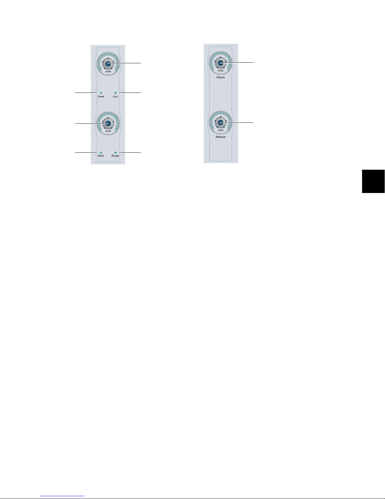
Knee/Hysteresis and Ratio/Range Controls
Knee/Hysteresis
encoder
Hysteresis
indicator
Knee
indicator
Ratio/Range
encoder
Ratio
indicator
Range
indicator
Attack
encoder
Release
encoder
Attack and Release Controls
Knee/Hysteresis and Ratio/Range controls in the Dynamics section
Knee/Hysteresis Control
The top encoder in this section controls the knee shape or the
hysteresis value for the current plug-in page, depending on
which indicator is lit. The Auto indicator under the encoder
knob lights when the displayed parameter is enabled for automation.
Ratio/Range Control
The bottom encoder in this section controls the compression
ratio or the range value for the current plug-in page, depending on which indicator is lit. The Auto indicator under the encoder knob lights when the displayed parameter is enabled for
automation.
Attack and Release controls in the Dynamics section
Attack Control
The top encoder in this section controls the attack value for
the current plug-in. The Auto indicator under the encoder
knob lights when the parameter is enabled for automation.
Release Control
The bottom encoder in this section controls the release value
for the current plug-in. The Auto indicator under the encoder
knob lights when the parameter is enabled for automation.
Chapter 7: Plug-in Controls 79
Page 88
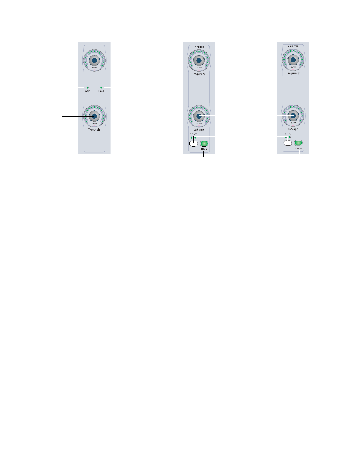
Gain/Hold and Threshold Controls
Gain/Hold
encoder
Hold
indicator
Gain
indicator
Threshold
encoder
Filter Frequency
encoders
Q/Slope
encoders
Notch/Shelf
switches
and indicators
Filter In
switches
Gain/Hold and Threshold controls in the Dynamics section
Gain/Hold Control
The top encoder in this section controls the gain (make-up
gain) or the hold value for the current plug-in page, depending on which indicator is lit. The Auto indicator under the encoder knob lights when the displayed parameter is enabled for
automation.
Threshold Control
The bottom encoder in this section controls the threshold
value for the current plug-in page. The Auto indicator under
the encoder knob lights when the parameter is enabled for automation.
Low Filter and High Filter Controls
Low Filter and High Filter controls in the Dynamics section
The Dynamics section includes controls for high- and low-frequency EQ filters available on certain dynamics plug-ins.
Filter Frequency Encoders
The top encoders in these sections control the filter frequency
for each filter. When the filter is a notch filter, these encoders
control the center frequency. When the filter is a high-pass or
low-pass filter, these encoders control the cutoff frequency.
Q/Slope Encoders
The bottom encoders in these sections control the Q value (for
notch filters) or the slope of the cutoff (for high-pass or
low-pass filters).
D-Control Guide80
Notch/Shelf Switch and Indicators
The Notch/Shelf switches in these sections let you switch between the two filter types when they are available. The indicators above the switch light to show which type of filter is active.
Filter In Switches
The Filter In switches in these sections let you engage or bypass each filter independently.
Page 89

Dynamics Channel Select Controls
Dynamics displays
Master Link switch
Bypass indicator
Select/Link/Bypass Mode switch
Channel Select switches
Channel Select controls in the Dynamics section
Dynamics Displays
The LED displays in the Dynamics section show the name of
the focused plug-in by default. When any rotary encoder is
touched, these displays show the corresponding parameter
name and value.
Channel Select Switches
Multichannel Plug-ins
When you are working with a multichannel plug-in, all channels are controlled in tandem and the Channel Select switches
have no effect.
Multi-Mono Plug-ins
When you are working with a multi-mono plug-in, the controls for the channels are usually linked and edited together.
However, you can edit plug-in settings for individual channels
of a multi-mono plug-in by using the Channel Select switches
to unlink all of the channels, or to link specific channels.
There are Channel Select switches for the following channels:
•L (Left)
• Lc (Left Center)
•C (Center)
• Rc (Right Center)
•R (Right)
•Ls (Left Surround)
•Cs (Center Surround)
•Rs(RightSurround)
•LFE
These choices support all possible channel configurations in
Pro Tools. A maximum of eight channels (7.1 surround) may
be in use at any time.
Master Link Switch
Multichannel Plug-ins
When you are working with a multichannel plug-in, all channels are controlled in tandem, and the Master Link switch has
no effect.
Multi-Mono Plug-ins
When you are working with a multi-mono plug-in, the Master
Link switch toggles the Master Link button in the plug-in window, which links or unlinks all channels of the plug-in. When
the Master Link button is enabled, the Link switch is lit.
Select/Link/Bypass Mode Switch
The Select/Link/Bypass Mode switch determines the function
of the Channel Select switches with multi-mono plug-ins.
Select Mode In this mode, the Channel Select switches determine which channel of a multi-mono plug-in is the focus of
the plug-in controls. When a channel is selected, its switch is
lit. If any channels are linked, their switches follow linked behavior.
In Select mode, if the D-Control Channel Window Display
preference is set to Yes, the Channel Select switches also
change the channel display in the plug-in window.
Bypass Mode In this mode, the Channel Select switches determine which channels of a multi-mono plug-in are bypassed.
When a channel is bypassed, its switch is lit. If any channels
are linked, their switches follow linked behavior.
Link Mode In this mode, the Channel Select switches determine which individual channels of a multi-mono plug-in are
linked together. Linked channels are indicated by switches
that are lit.
Chapter 7: Plug-in Controls 81
Page 90

Dynamics Edit and Display Controls
Page s witch
External Key switch
Compare switch
Cycle switch
Bypass switch
Key Listen
switch
Save As
switch
Lock
switch
Automation switch
Automation Safe switch
Window switch
Edit and Display controls in the Dynamics section
Page Switch
With plug-ins that have more than one page of controls, the
Page switch lights. Pressing this switch steps through the
pages for the currently displayed plug-in.
Active paged controls are shown in the plug-in window by colored outlines.
External Key Switch
The External Key switch turns the Key Input on or off for
plug-ins that support side-chain processing with external input. This switch lights when Key Input is on.
Key Listen Switch
The Key Listen switch turns the Key Listen function on or off
for plug-ins that support auditioning the Key Input. This
switch lights when Key Listen is on.
Save As Switch
The Save As switch performs the Save As command in the
Plug-in settings menu.
To save a Dynamics plug-in setting from D-Control:
1 Press the Save As switch in the Edit and Display controls of
the Dynamics section. The Save As switch flashes while the
Save Settings dialog is open.
2 Type a name for the plug-in setting.
3 Do one of the following:
• Click OK to save the settings and close the dialog.
• Press the flashing Save As switch to save the settings and
close the dialog.
• Press the Escape switch to exit the dialog without saving
the settings.
D-Control Guide82
Page 91

Lock Switch
Safe Switch
The Lock switch is used to lock the focus of the Dynamics section on the current plug-in. When the plug-in focus is locked,
the current plug-in remains in the Dynamics section, even
when a different track is focused on D-Control. This switch
lights when the plug-in focus is locked.
Compare Switch
The Compare switch toggles the Compare button in the
plug-in window, which alternates between the currently saved
plug-in setting and any changes you have made.
Automation Switch
The Automation switch lets you enable Dynamics parameters
for automation by touching or pressing their controls in the
Dynamics section only.
In Automation mode, the Auto switch is lit. While in this
mode, the Auto LED for any rotary encoder enabled for automation is lit red, and the switch for any parameter enabled for
automation is lit.
To toggle automation on and off for individual Dynamics
parameters:
1 Press the Automation switch.
The Safe switch toggles the Safe button in the plug-in window,
which protects existing automation for that plug-in from being overwritten.
Cycle Switch
The Cycle switch steps through all available Dynamics
plug-ins on the focused channel.
Bypass Switch
The Bypass switch bypasses the plug-in.
Window Switch
The Window switch is used to open and close the on-screen
window for the currently focused plug-in.
2 Touch the rotary encoders or press the switches in the Dy-
namics section for which you want to toggle automation.
3 Press the Automation switch again to exit Automation
mode.
To toggle automation on and off for all parameters of a Dynamics
plug-in:
1 Press the Automation switch.
2 Do one of the following:
• Hold Alt (Windows) or Option (Mac).
– or –
• Hold Do to All.
3 Touch any rotary encoder or press any switches in the Dy-
namics section.
4 Press the Automation switch again to exit Automation
mode.
Chapter 7: Plug-in Controls 83
Page 92

Dynamics Gain Controls and Meters
Input Gain encoder
Output Gain encoder
Clip indicator
Input meter
Output meter
Compressor/Limiter
Gain Reduction
meter
Expander/Gate
Gain Reduction
meter
Level controls (left) and meters (right) in the Dynamics section
Input and Output Gain Encoders
The Input and Output Gain encoders control the input gain and output gain for the current plug-in. The Auto indicator under
each encoder knob lights when the parameter is enabled for automation.
Input and Output Meters and Clip Indicator
The Input and Output meters show the input and output levels for the current plug-in. The Clip indicator lights when a clip is
reported by the plug-in, and can be cleared by pressing the Clear Clip switch in the Session Management section.
Gain Reduction Meters
The Gain Reduction meters show the amount of gain reduction for Compressor/Limiter functions (on the left) and Expander/Gate functions (on the right).
You can also display gain reduction metering for dynamics plug-ins directly on channel meters in Normal mode. See “Displaying
Dynamics Plug-in Gain Reduction on Channel Meters” on page 77.
D-Control Guide84
Page 93

EQ Section
High-Pass
Filter
Low
Filter
Low-Mid
Filter
Mid
Filter
High-Mid
Filter
High
Filter
Low-Pass
Filter Level
controls
Channel Select
switches
Input and Output metersEQ Edit and Display controls
controls controls controlscontrolscontrolscontrolscontrols
The EQ section includes standard controls for a variety of multi-band plug-ins, an array of controls for managing the display and
editing of plug-in parameters, and controls for selecting or linking channels in multi-mono plug-ins.
D-Control EQ section
EQ Plug-in Support
EQ processing plug-ins may have widely varying controls, depending on their applications. The D-Control EQ Section provides dedicated knobs and switches to accommodate the widest range of plug-ins possible. Not all plug-ins will require all
the EQ controls, while others may have more parameters than
can be displayed in the EQ section at one time.
To simultaneously display all controls in any plug-in, you can
use Custom Fader Plug-ins mode.
Displaying EQ Plug-ins
The D-Control EQ section automatically displays the first EQ
plug-in on the channel that is focused in the Focus Channel
Strip on the Main Unit.
To display successive EQ plug-ins that are on the focused
channel, press the Cycle switch in the EQ section.
Chapter 7: Plug-in Controls 85
Page 94

High-Pass Filter and Low-Pass Filter
Q encoders
Notch/Shelf switches
and indicators
Frequency encoders
Filter In switches
Q encoders
Notch/Shape switches
and indicators
Frequency encoders
Band In switches
Gain encoders
Controls
Low Shelf/Peak and High Shelf/Peak
EQ Controls
There are similar controls for high-pass and low-pass filters on
the extreme left and right sides of the EQ section.
High-Pass Filter and Low-Pass Filter controls in the EQ section
Q Encoders
The top encoders for these EQ bands control the Q of each filter. The Auto indicator under each encoder knob lights when
the parameter is enabled for automation.
Notch/Shelf Switches and Indicators
The Notch/Shelf switches in these EQ bands let you switch between the two filter types when they are available. The indicators on either side of the switch light to show which type of filter is active.
Frequency Encoders
The bottom encoders in these EQ bands control the filter frequency for each filter. When the filter is a notch filter, these
encoders control the center frequency. When the filter is a
high-pass or low-pass filter, these encoders control the cutoff
frequency. The Auto indicator under each encoder knob lights
when the parameter is enabled for automation.
Band In Switches
The Band In switches in these EQ bands let you engage or bypass their corresponding EQ band in the plug-in.
There are similar controls for the low and high shelf/peak EQ
bands on the left and right sides of the EQ section, just inside
the high-pass and low-pass filter controls.
Low Filter and High Filter controls in the EQ section
Q Encoders
The top encoders for these EQ bands control the Q of each
band. The Auto indicator under each encoder knob lights
when the parameter is enabled for automation.
Notch/Shape Switch and Indicators
The Notch/Shape switches in these EQ bands let you switch
between the two EQ types when they are available. The indicators on either side of the switch light to show which type of
EQ is active.
Frequency Encoders
The middle encoders in these EQ bands control the frequency
for each band. When the EQ is a peaking type, these encoders
control the center frequency. When the EQ is a high- or
low-shelf type, these encoders control the cutoff frequency.
The Auto indicator under each encoder knob lights when the
parameter is enabled for automation.
Gain Encoders
The bottom encoders in these EQ bands control the gain for
each band. The Auto indicator under each encoder knob lights
when the parameter is enabled for automation.
D-Control Guide86
Band In Switches
The Band In switches in these EQ bands let you engage or bypass their corresponding EQ band in the plug-in.
Page 95

Low-Mid, Mid, and High-Mid EQ Band Controls
Q encoders
Frequency encoders
Gain encoders
Band In switches
There are similar controls for low-mid, mid, and high-mid EQ bands in the center of the EQ section.
Low-Mid, Mid and High-Mid EQ band controls in the EQ section
Q Encoders
The top encoders for these EQ bands control Q values for each band. The Auto indicator under each encoder knob lights when
the parameter is enabled for automation.
Frequency Encoders
The middle encoders in these EQ bands control the center frequency for each band. The Auto indicator under each encoder knob
lights when the parameter is enabled for automation.
Gain Encoders
The bottom encoders in these EQ bands control the gain for each band. The Auto indicator under each encoder knob lights when
the parameter is enabled for automation.
Band In Switches
The Band In switches in these EQ bands let you engage or bypass the corresponding EQ band in the plug-in.
Chapter 7: Plug-in Controls 87
Page 96
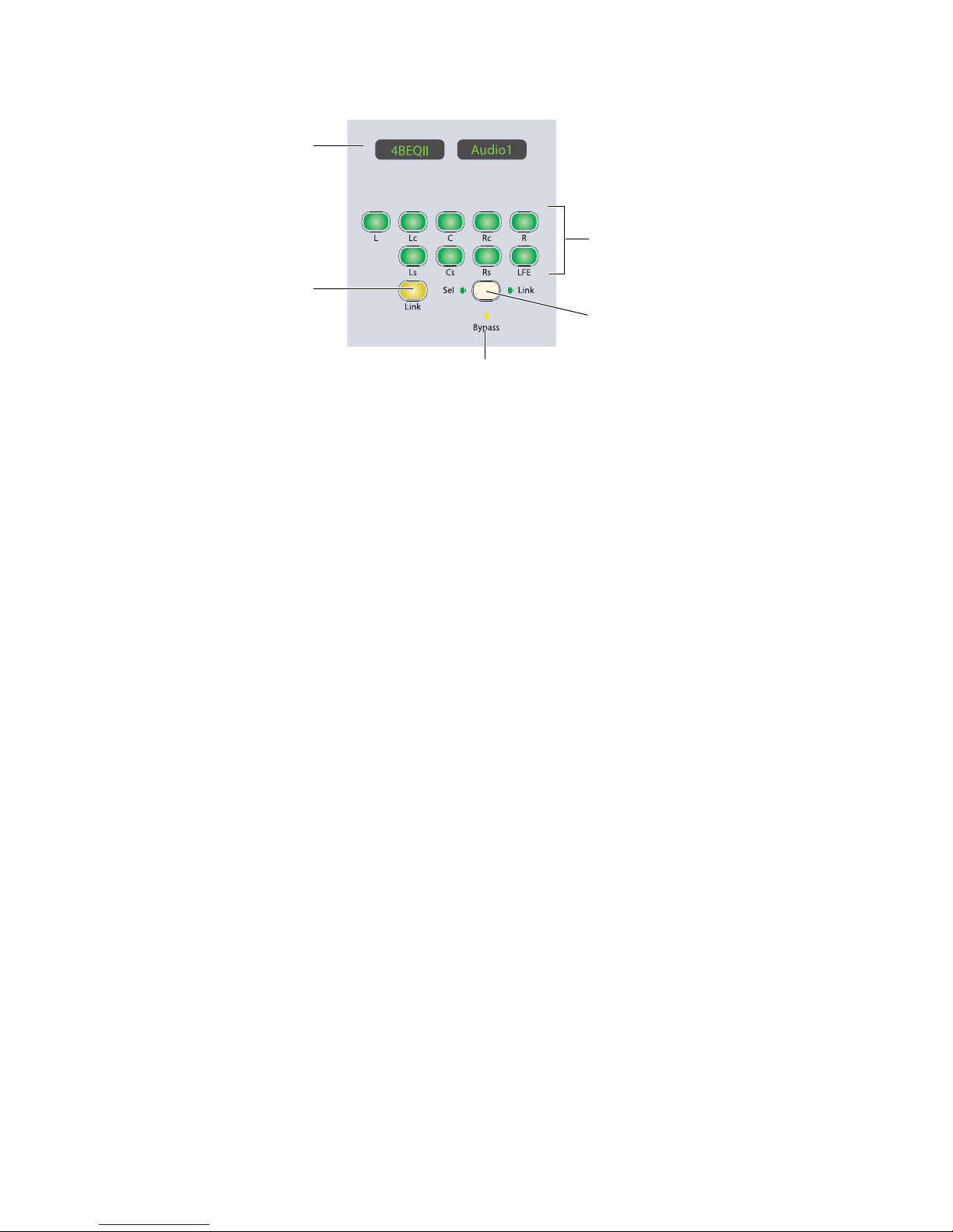
EQ Channel Select Controls
EQ displays
Link switch
Select/Link/Bypass Mode switch
Channel Select switches
Bypass indicator
Channel Select controls in the EQ section
EQ Displays
The LED displays in the EQ section show the name of the focused plug-in by default. When any rotary encoder is touched,
these displays show the corresponding parameter name and
value.
Channel Select Switches
Multichannel Plug-ins
When you are working with a multichannel plug-in, all channels are controlled in tandem and the Channel Select switches
have no effect, except with multichannel plug-ins (such as
Focusrite d2) that directly support channel selection.
Multi-Mono Plug-ins
When you are working with a multi-mono plug-in, the controls for the channels are usually linked and edited together.
However, you can edit plug-in settings for individual channels
of a multi-mono plug-in by unlinking all of the channels, or
by using the Channel Select switches to link specific channels.
There are Channel Select switches for the following channels:
•L (Left)
• Lc (Left Center)
•C (Center)
• Rc (Right Center)
•R (Right)
•Ls (Left Surround)
•Cs (Center Surround)
•Rs(RightSurround)
•LFE
These choices support all possible channel configurations in
Pro Tools. A maximum of eight channels (7.1 surround) may
be in use at any time.
D-Control Guide88
Master Link Switch
Multichannel Plug-ins
When you are working with a multichannel plug-in, all channels are controlled in tandem, so the Master Link switch has
no effect, except with multichannel plug-ins (such as
Focusrite d2) that directly support channel linking.
Multi-Mono Plug-ins
When you are working with a multi-mono plug-in, the Master
Link switch toggles the Master Link button in the plug-in window, which links or unlinks all channels of the plug-in. When
the Master Link button is enabled, the Link switch is lit.
Select/Link/Bypass Mode Switch
The Select/Link/Bypass Mode switch determines the function
of the Channel Select switches with multi-mono plug-ins.
Select Mode In this mode, the Channel Select switches determine which channel of a multi-mono plug-in is the focus of
the plug-in controls. When a channel is selected, its switch is
lit. If any channels are linked, their switches follow linked behavior.
In Select mode, if the D-Control Channel Window Display
preference is set to Yes, the Channel Select switches also
change the channel display in the plug-in window.
Bypass Mode In this mode, the Channel Select switches determine which channels of a multi-mono plug-in are bypassed.
When a channel is bypassed, its switch is lit. If any channels
are linked, their switches follow linked behavior.
Link Mode In this mode, the Channel Select switches determine which individual channels of a multi-mono plug-in are
linked together. Linked channels are indicated by switches
that are lit.
Page 97
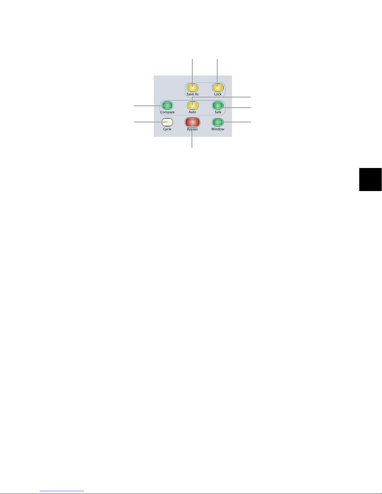
EQ Edit and Display Controls
Compare switch
Cycle switch
Master Bypass switch
Save As
switch
Lock
switch
Automation switch
Automation Safe switch
Window switch
Edit and Display controls in the EQ section
Save As Switch
The Save As switch performs the Save As command in the
Plug-in settings menu, which saves a new settings file for the
plug-in.
To save an EQ plug-in setting from D-Control:
1 Press the Save As switch in the Edit and Display controls of
the Dynamics section. The Save As switch flashes while the
Save Settings dialog is open.
2 Type a name for the plug-in setting.
3 Do one of the following:
• Click OK to save the settings and close the dialog.
• Press the flashing Save As switch to save the settings and
close the dialog.
• Press the Escape switch to exit the dialog without saving
the settings.
Lock Switch
The Lock switch is used to lock the focus of the EQ section on
the current plug-in. When the plug-in focus is locked, the current plug-in remains in the EQ section, even when a different
track is focused on D-Control. This switch lights when the
plug-in focus is locked.
Compare Switch
The Compare switch toggles the Compare button in the
plug-in window, which alternates between the currently saved
plug-in setting and any changes you have made.
Automation Switch
The Automation switch lets you enable EQ parameters for automation by touching or pressing their controls in the EQ section only.
In Automation mode, the Auto switch is lit. While in this
mode, the Auto indicator for any rotary encoder enabled for
automation is lit red, and the switch for any parameter enabled for automation is lit.
To toggle automation on and off for individual EQ parameters:
1 Press the Automation switch.
2 Touch the rotary encoders or press the switches in the EQ
section for which you want to toggle automation.
3 Press the Automation switch again to exit Automation
mode.
To toggle automation on and off for all parameters of an EQ
plug-in:
1 Press the Automation switch.
2 Do one of the following:
• Hold Alt (Windows) or Option (Mac).
– or –
• Hold Do to All.
3 Touch any rotary encoder or press any switches in the EQ
section.
4 Press the Automation switch again to exit Automation
mode.
Chapter 7: Plug-in Controls 89
Page 98

Safe Switch
Input Gain encoder
Output Gain encoder
Clip indicator
Input meter
Output meter
The Safe switch toggles the Safe but to n in the plug-in window,
which protects existing automation for that plug-in from being overwritten.
Cycle Switch
The Cycle switch steps through all available EQ plug-ins on
the focused channel.
Bypass Switch
The Bypass switch bypasses the plug-in.
Window Switch
The Window switch is used to open and close the on-screen
window for the currently focused plug-in.
EQ Level Controls and Meters
Level controls and meters in the EQ section
Input and Output Gain Encoders
The Input and Output Gain encoders control the input gain
and output gain for the current plug-in. The Auto indicator
under each encoder knob lights when the parameter is enabled for automation.
Input and Output Meters and Clip Indicator
The Input and Output meters show the input and output levels for the current plug-in. The Clip indicator lights when a
clip is reported by the plug-in, and can be cleared by pressing
the Clear Clip switch in the Session Management section.
D-Control Guide90
Page 99
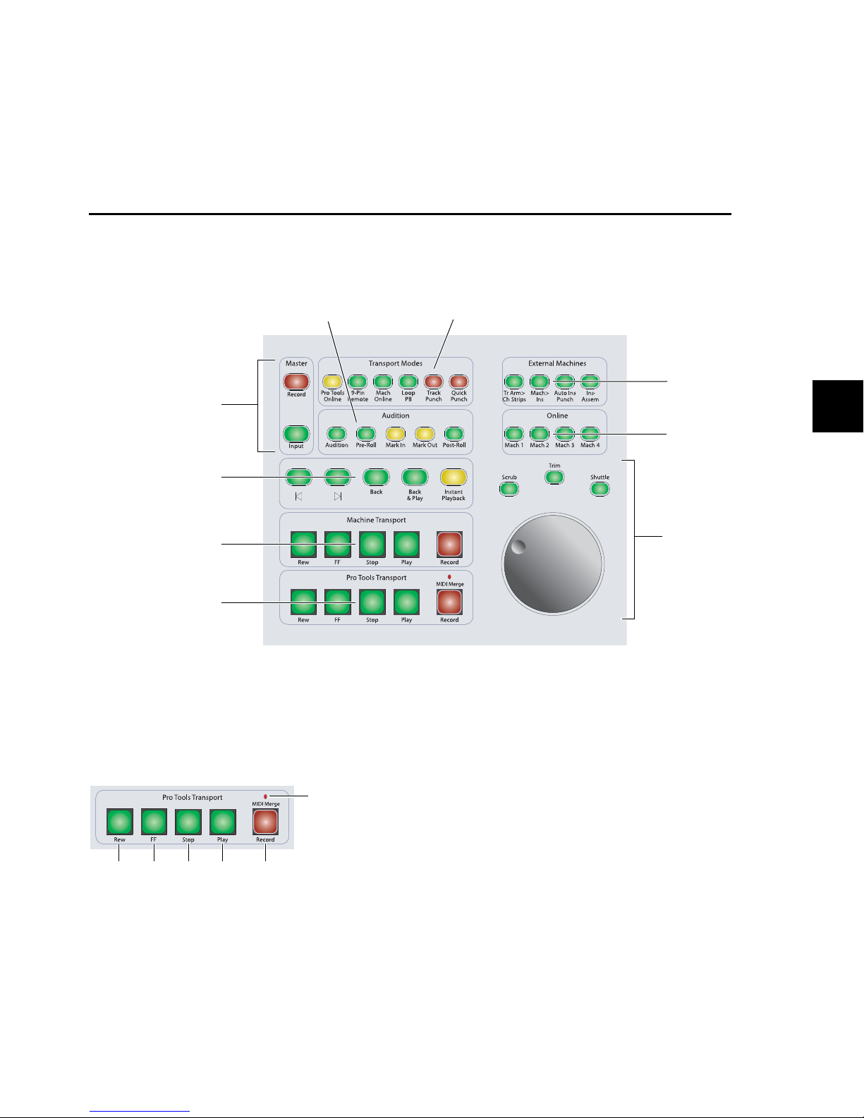
Chapter 8: Transport and Navigation Controls
Scrub/Shuttle
switches and controls
Machine Transport
switches
Pr o Too ls Tr a n s p o r t
switches
External Machines
switches
Online switches
Transport Mode switchesAudition switches
Locate switches
Master Record Mode
switches
Rewind Fast
Forward
Stop Play Record
MIDI Merge
indicator
Transport Section
The D-Control Transport section includes two complete sets of transport switches, switches for setting the transport mode,
scrub/shuttle switches and controls, and advanced audition and locate switches.
D-Control Transport Section
Transport Switches
D-Control has two sets of transport switches, one for
Pro Tools, and the other reserved for external machines controlled with Digidesign MachineControl.
Pro Tools Transport switches
Pro Tools Transpor t
The D-Control Pro Tools Transport switches correspond to the
controls in the Pro Tools Transport window.
Rewind Switch Moves backward through the Pro Tools session
beginning from the current cursor position.
Fast Forward Switch Moves forward through the Pro Tools session beginning from the current cursor position.
Stop Switch Stops playback of the Pro Tools session.
Play Switch Begins playback of the Pro Tools session from the
current cursor position.
Record Switch Arms Pro Tools for recording. Exact function
depends on current Pro Tools record mode (QuickPunch,
TrackPunch, Wait for Note, Pause).
MIDI Merge Indicator Shows when MIDI Merge is activated.
Machine Transport
With Digidesign MachineControl, you can place D-Control in
Dual Transport mode, which activates the Machine Transport
switches. These switches can then be assigned to control an
external 9-pin or MMC device.
Chapter 8: Transport and Navigation Controls 91
Page 100

Scrub/Shuttle Controls
Scrub
switch
Tri m
switch
Shuttle
switch
Scrub/Shuttle
Wheel
Selecting with the Scrub/Shuttle Wheel
The Scrub/Shuttle controls are used for the following:
• Edit cursor operations, including scrubbing, scrubbing
while trimming, shuttling, and making selections.
• Zooming, Pro Tools window navigation, and banking faders
on D-Control.
Scrub/Shuttle controls
Scrub/Shuttle Wheel
The Scrub/Shuttle wheel is used to control cursor position in
Pro Tools, and for zooming, window navigation, and banking
faders.
Scrolling and Locating in Pro Tools Windows
To create selections with the Scrub/Shuttle wheel:
1 Locate the cursor in a track.
2 Press the Scrub switch or the Shuttle switch.
3 Do one of the following:
• Hold the Mark In switch and turn the Scrub/Shuttle
wheel counter-clockwise to create or extend the selection
to the left.
– or –
• Hold the Mark Out switch and turn the Scrub/Shuttle
wheel clockwise to create or extend the selection to the
right.
To scrub while adding to the front of a selection:
Hold Start+Shift (Windows) or Control + Shift (Mac) while
scrubbing the front of the selection.
To scrub while adding to the end of a selection:
Hold Start+Shift+Alt (Windows) or Control+Shift+Option
(Mac) while scrubbing the end of the selection.
To scrub with fine resolution while adding to the front of a
selection:
Hold Start+Shift+Control (Windows) or Con-
trol+Shift+Command (Mac) while scrubbing the front of the
selection.
To horizontally scroll the contents of the Edit window or Mix
window:
1 Focus the window you want to scroll by clicking in it or by
pressing the corresponding window key in the Window Management section.
2 Hold Alt (Windows) or Option (Mac) while turning the
Scrub/Shuttle Wheel.
To vertically scroll the contents of the Edit window or Mix
window:
1 Focus the window you want to scroll by clicking in it or by
pressing the corresponding window key in the Window Management section.
2 Hold Shift while turning the Scrub/Shuttle Wheel.
To locate the cursor in the Edit window while in Continuous Scroll
Mode:
Hold Control+Alt+Start (Windows) or Command+Op-
tion+Control (Mac) and press the Mark In or Mark Out switch
in the Audition section.
To scrub with fine resolution while adding to the end of a
selection:
Hold Start+Shift+Alt+Control (Windows) or Con-
trol+Shift+Option+Command (Mac) while scrubbing the end
of the selection.
Continuous Zooming in the Edit Window
To horizontally zoom continuously in the Edit window:
Hold Control (Windows) or Command (Mac) while turning
the Scrub/Shuttle Wheel.
To vertically zoom continuously in the Edit window:
Hold Control+Alt (Windows) or Command+Option (Mac)
while turning the Scrub/Shuttle Wheel.
Moving Windows On-Screen with the Scrub/Shuttle Wheel
To move a Pro Tools window horizontally on-screen:
In the Window Management section, hold the switch for
the window and turn the Scrub/Shuttle wheel.
D-Control Guide92
 Loading...