

Page 1

VENUE Profile™ Guide
and VENUE D-Show® Software Version 2.8.1
Digidesign
2001 Junipero Serra Boulevard
Daly City, CA 94014-3886 USA
Technical Support (USA)
Visit the Digidesign Online Support Center at
www.digidesign.com/support
Product Information
For company and product information,
visit us on the web at www.digidesign.com
Guide Part Number: 9322-61364-00 REV A
Page 2
Legal Notices
This guide is copyrighted ©2009 by Digidesign, a division of Avid Technology, Inc.
(hereafter “Digidesign”), with all rights reserved. Under copyright laws, this guide
may not be duplicated in whole or in part without the written consent of
Digidesign.
003, 003 Rack, 96 I/O, 96i I/O, 192 Digital I/O, 192 I/O, 888|24 I/O, 882|20
I/O, 1622 I/O, 24-Bit ADAT Bridge I/O, AudioSuite, Avid, Avid DNA, Avid Mojo,
Avid Unity, Avid Unity ISIS, Avid Unity MediaNetwork, Avid Xpress, AVoption,
AVoption|V10, Beat Detective, Bruno, C|24, Command|8, Control|24,
D-Command, D-Control, D-Fi, D-fx, D-Show, DAE, Digi 002, Digi 002 Rack,
DigiBase, DigiDelivery, Digidesign, Digidesign Audio Engine, Digidesign
Intelligent Noise Reduction, Digidesign TDM Bus, DigiDrive, DigiRack, DigiTest,
DigiTranslator, DINR, DV Toolkit, EditPack, Eleven, Impact, Interplay, M-Audio,
MachineControl, Maxim, Mbox, MediaComposer, MIDI I/O, MIX, MultiShell, OMF,
OMF Interchange, PRE, ProControl, Pro Tools M-Powered, Pro Tools,
Pro Tools|HD, Pro Tools LE, QuickPunch, Reel Tape, Reso, Reverb One, ReVibe,
RM1, RM2, RTAS, Smack!, SoundReplacer, Sound Designer II, Strike, Structure,
SYNC HD, SYNC I/O, Synchronic, TL Space, Velvet, X-Form, and Xpand! are
trademarks or registered trademarks of Digidesign and/or Avid Technology, Inc.
All other trademarks are the property of their respective owners.
Product features, specifications, system requirements, and availability are
subject to change without notice.
Guide Part Number: 9322-61364-00 REV A 04/09
Comments or suggestions regarding our documentation?
email: techpubs@digidesign.com
Communications & Safety Regulation Information
Compliance Statement
The model VENUE Profile complies with the following standards regulating
interference and EMC:
• FCC Part 15 Class B
• EN55103-1 E3
• EN55103-2 E3
• AS/NZS 3548 Class B
• CISPR 22 Class B
Radio and Television Interference
This equipment has been tested and found to comply with the limits for a Class
B digital device, pursuant to Part 15 of the FCC Rules.
DECLARATION OF CONFORMITY
We, Digidesign, 2001 Junipero Serra Boulevard
Daly City, CA 94014-3886, USA
650-731-6300
declare under our sole responsibility that the product
VENUE Profile
complies with Part 15 of FCC Rules.
Operation is subject to the following two conditions: (1) this device may not
cause harmful interference, and (2) this device must accept any interference
received, including interference that may cause undesired operation.
Communication Statement
NOTE: This equipment has been tested and found to comply with the limits for a
Class B digital device, pursuant to Part 15 of the FCC Rules. These limits are
designed to provide reasonable protection against harmful interference in a
residential installation. This equipment generates, uses, and can radiate radio
frequency energy and, if not installed and used in accordance with the
instructions, may cause harmful interference to radio communications. However,
there is no guarantee that interference will not occur in a particular installation.
If this equipment does cause harmful interference to radio or television
reception, which can be determined by turning the equipment off and on, the user
is encouraged to try and correct the interference by one or more of the following
measures:
• Reorient or locate the receiving antenna.
• Increase the separation between the equipment and receiver.
• Connect the equipment into an outlet on a circuit different from that to which
the receiver is connected.
• Consult the dealer or an experienced radio/TV technician for help.
Any modifications to the unit, unless expressly approved by Digidesign, could
void the user's authority to operate the equipment.
Canadian Compliance Statement:
This Class B digital apparatus complies with Canadian ICES-003
Cet appareil numérique de la classe B est conforme à la norme NMB-003 du
Canada
Australian Compliance
CE Compliance Statement:
Digidesign is authorized to apply the CE (Conformité Europénne) mark on this
compliant equipment thereby declaring conformity to EMC Directive
89/336/EEC and Low Voltage Directive 73/23/EEC.
Input Rating
I/P: 100-120V~/220-240V~, 50/60 Hz, 200W
Page 3

Safety Statement
This equipment has been tested to comply with USA and Canadian safety
certification in accordance with the specifications of UL Standards: UL60065 7th
/IEC 60065 7th and Canadian CAN/CSA C22.2 60065:03. Digidesign Inc., has
been authorized to apply the appropriate UL & CUL mark on its compliant
equipment.
Warning
Important Safety Instructions
1) Read these instructions.
2) Keep these instructions.
3) Heed all warnings.
4) Follow all instructions.
5) Do not use this equipment near water.
6) Clean only with dry cloth.
7) Do not block any ventilation openings. Install in accordance with the
manufacturer’s instructions.
8) Do not install near any heat sources such as radiators, heat registers, stoves,
or other equipment (including amplifiers) that produce heat.
9) Do not defeat the safety purpose of the polarized or grounding-type plug. A
polarized plug has two blades with one wider than the other. A grounding type
plug has two blades and a third grounding prong. The wide blade or the third
prong are provided for your safety. If the provided plug does not fit into your
outlet, consult an electrician for replacement of the obsolete outlet.
10) Protect power cords from being walked on or pinched particularly at plugs,
convenience receptacles, and the point where they exit from the equipment.
11) Only use attachments/accessories specified by the manufacturer.
12) Use only with a cart, stand, tripod, bracket, or table specified by the
manufacturer, or sold with the equipment. When a cart is used, use caution when
moving the cart/equipment combination to avoid injury from tip-over.
13) Unplug this equipment during lightning storms or when unused for long
periods of time.
14) Refer all servicing to qualified service personnel. Servicing is required when
the equipment has been damaged in any way, such as power-supply cord or plug
is damaged, liquid has been spilled or objects have fallen into the equipment,
the equipment has been exposed to rain or moisture, does not operate normally,
or has been dropped.
15) The equipment shall not be exposed to dripping or splashing and no objects
filled with liquids (such as vases) shall be placed on the equipment.
Warning! To reduce the risk of fire or electric shock, do not expose this
equipment to rain or moisture.
16) The equipment should be connected to a properly-grounded (earthed)
receptacle.
17) The main power switch is located on the back panel. It should remain
accessible after installation.
18) The mains plug is used as the disconnecting device and shall remain readily
operable.
19) The equipment shall be used at a maximum ambient temperature of 40° C.
20) CAUTION! Danger of explosion if battery is incorrectly replaced.
Replace only with the same or equivalent type.
Page 4

Page 5

Contents
Part I Overview and Installation
Chapter 1. Introduction to VENUE Profile . . . . . . . . . . . . . . . . . . . . . . . . . . . . . . . . . . . . . . . . . . . . . . . . . . . . . . . . . . . 3
VENUE Profile Systems and Features . . . . . . . . . . . . . . . . . . . . . . . . . . . . . . . . . . . . . . . . . . . . . . . . . . . . . . . . . . . . . . . 3
System Components . . . . . . . . . . . . . . . . . . . . . . . . . . . . . . . . . . . . . . . . . . . . . . . . . . . . . . . . . . . . . . . . . . . . . . . . . . . 5
VENUE Profile Expansion Options . . . . . . . . . . . . . . . . . . . . . . . . . . . . . . . . . . . . . . . . . . . . . . . . . . . . . . . . . . . . . . . . . . 5
Operational Requirements . . . . . . . . . . . . . . . . . . . . . . . . . . . . . . . . . . . . . . . . . . . . . . . . . . . . . . . . . . . . . . . . . . . . . . . 7
Connection Requirements . . . . . . . . . . . . . . . . . . . . . . . . . . . . . . . . . . . . . . . . . . . . . . . . . . . . . . . . . . . . . . . . . . . . . . . 7
Registration . . . . . . . . . . . . . . . . . . . . . . . . . . . . . . . . . . . . . . . . . . . . . . . . . . . . . . . . . . . . . . . . . . . . . . . . . . . . . . . . . 8
Conventions Used in This Guide . . . . . . . . . . . . . . . . . . . . . . . . . . . . . . . . . . . . . . . . . . . . . . . . . . . . . . . . . . . . . . . . . . . 8
About www.digidesign.com . . . . . . . . . . . . . . . . . . . . . . . . . . . . . . . . . . . . . . . . . . . . . . . . . . . . . . . . . . . . . . . . . . . . . . 8
Chapter 2. Configuring and Connecting Profile . . . . . . . . . . . . . . . . . . . . . . . . . . . . . . . . . . . . . . . . . . . . . . . . . . . . . . 9
Unpacking and Assembling VENUE Profile . . . . . . . . . . . . . . . . . . . . . . . . . . . . . . . . . . . . . . . . . . . . . . . . . . . . . . . . . . . . 9
Assembling the Video Monitor Mount and Trackball Mount . . . . . . . . . . . . . . . . . . . . . . . . . . . . . . . . . . . . . . . . . . . . . . . . 9
Connections for VENUE Mix Rack Systems. . . . . . . . . . . . . . . . . . . . . . . . . . . . . . . . . . . . . . . . . . . . . . . . . . . . . . . . . . . 12
Connections for VENUE Profile Systems . . . . . . . . . . . . . . . . . . . . . . . . . . . . . . . . . . . . . . . . . . . . . . . . . . . . . . . . . . . . . 15
Profile Console Connections . . . . . . . . . . . . . . . . . . . . . . . . . . . . . . . . . . . . . . . . . . . . . . . . . . . . . . . . . . . . . . . . . . . . . 20
Powering Up the System . . . . . . . . . . . . . . . . . . . . . . . . . . . . . . . . . . . . . . . . . . . . . . . . . . . . . . . . . . . . . . . . . . . . . . . 21
Powering Down the System . . . . . . . . . . . . . . . . . . . . . . . . . . . . . . . . . . . . . . . . . . . . . . . . . . . . . . . . . . . . . . . . . . . . . 21
Setting the System Clock . . . . . . . . . . . . . . . . . . . . . . . . . . . . . . . . . . . . . . . . . . . . . . . . . . . . . . . . . . . . . . . . . . . . . . . 21
Enabling a Second Stage Rack . . . . . . . . . . . . . . . . . . . . . . . . . . . . . . . . . . . . . . . . . . . . . . . . . . . . . . . . . . . . . . . . . . . 22
Digital Inputs and Sample Rate Conversion . . . . . . . . . . . . . . . . . . . . . . . . . . . . . . . . . . . . . . . . . . . . . . . . . . . . . . . . . . 22
Part II System Description
Chapter 3. VENUE Profile Control Overview . . . . . . . . . . . . . . . . . . . . . . . . . . . . . . . . . . . . . . . . . . . . . . . . . . . . . . . . 27
VENUE Profile Top Panel . . . . . . . . . . . . . . . . . . . . . . . . . . . . . . . . . . . . . . . . . . . . . . . . . . . . . . . . . . . . . . . . . . . . . . . 27
Input Channels and Faders. . . . . . . . . . . . . . . . . . . . . . . . . . . . . . . . . . . . . . . . . . . . . . . . . . . . . . . . . . . . . . . . . . . . . . 28
Assignable Channel Section . . . . . . . . . . . . . . . . . . . . . . . . . . . . . . . . . . . . . . . . . . . . . . . . . . . . . . . . . . . . . . . . . . . . . 32
Output Masters . . . . . . . . . . . . . . . . . . . . . . . . . . . . . . . . . . . . . . . . . . . . . . . . . . . . . . . . . . . . . . . . . . . . . . . . . . . . . . 34
Master and Global Controls . . . . . . . . . . . . . . . . . . . . . . . . . . . . . . . . . . . . . . . . . . . . . . . . . . . . . . . . . . . . . . . . . . . . . 35
Meters . . . . . . . . . . . . . . . . . . . . . . . . . . . . . . . . . . . . . . . . . . . . . . . . . . . . . . . . . . . . . . . . . . . . . . . . . . . . . . . . . . . . 36
Chapter 4. Basic Commands and Modes . . . . . . . . . . . . . . . . . . . . . . . . . . . . . . . . . . . . . . . . . . . . . . . . . . . . . . . . . . . 37
Control Overview . . . . . . . . . . . . . . . . . . . . . . . . . . . . . . . . . . . . . . . . . . . . . . . . . . . . . . . . . . . . . . . . . . . . . . . . . . . . . 37
Config Mode and Show Mode . . . . . . . . . . . . . . . . . . . . . . . . . . . . . . . . . . . . . . . . . . . . . . . . . . . . . . . . . . . . . . . . . . . . 38
System Lock. . . . . . . . . . . . . . . . . . . . . . . . . . . . . . . . . . . . . . . . . . . . . . . . . . . . . . . . . . . . . . . . . . . . . . . . . . . . . . . . 38
Global Modifier Switches . . . . . . . . . . . . . . . . . . . . . . . . . . . . . . . . . . . . . . . . . . . . . . . . . . . . . . . . . . . . . . . . . . . . . . . 39
Software Screen Pages and Tabs . . . . . . . . . . . . . . . . . . . . . . . . . . . . . . . . . . . . . . . . . . . . . . . . . . . . . . . . . . . . . . . . . 40
Contents v
Page 6

Chapter 5. Navigating and Selecting Channels . . . . . . . . . . . . . . . . . . . . . . . . . . . . . . . . . . . . . . . . . . . . . . . . . . . . . . 43
Banking Input Channels and FX Returns. . . . . . . . . . . . . . . . . . . . . . . . . . . . . . . . . . . . . . . . . . . . . . . . . . . . . . . . . . . . . 43
Banking the Output Section. . . . . . . . . . . . . . . . . . . . . . . . . . . . . . . . . . . . . . . . . . . . . . . . . . . . . . . . . . . . . . . . . . . . . . 46
Selecting and Targeting Channels . . . . . . . . . . . . . . . . . . . . . . . . . . . . . . . . . . . . . . . . . . . . . . . . . . . . . . . . . . . . . . . . . 46
Targeting Plug-In Inserts . . . . . . . . . . . . . . . . . . . . . . . . . . . . . . . . . . . . . . . . . . . . . . . . . . . . . . . . . . . . . . . . . . . . . . . . 47
Screen Controls . . . . . . . . . . . . . . . . . . . . . . . . . . . . . . . . . . . . . . . . . . . . . . . . . . . . . . . . . . . . . . . . . . . . . . . . . . . . . . 48
Screen Shortcuts . . . . . . . . . . . . . . . . . . . . . . . . . . . . . . . . . . . . . . . . . . . . . . . . . . . . . . . . . . . . . . . . . . . . . . . . . . . . . 49
Input Channel Presets. . . . . . . . . . . . . . . . . . . . . . . . . . . . . . . . . . . . . . . . . . . . . . . . . . . . . . . . . . . . . . . . . . . . . . . . . . 52
Chapter 6. Options . . . . . . . . . . . . . . . . . . . . . . . . . . . . . . . . . . . . . . . . . . . . . . . . . . . . . . . . . . . . . . . . . . . . . . . . . . . . . . . 55
System . . . . . . . . . . . . . . . . . . . . . . . . . . . . . . . . . . . . . . . . . . . . . . . . . . . . . . . . . . . . . . . . . . . . . . . . . . . . . . . . . . . . 55
Devices . . . . . . . . . . . . . . . . . . . . . . . . . . . . . . . . . . . . . . . . . . . . . . . . . . . . . . . . . . . . . . . . . . . . . . . . . . . . . . . . . . . . 57
Other Options and Settings . . . . . . . . . . . . . . . . . . . . . . . . . . . . . . . . . . . . . . . . . . . . . . . . . . . . . . . . . . . . . . . . . . . . . . 57
Part III Signal Routing
Chapter 7. Inputs and Input Routing . . . . . . . . . . . . . . . . . . . . . . . . . . . . . . . . . . . . . . . . . . . . . . . . . . . . . . . . . . . . . . . 67
Configuring Inputs . . . . . . . . . . . . . . . . . . . . . . . . . . . . . . . . . . . . . . . . . . . . . . . . . . . . . . . . . . . . . . . . . . . . . . . . . . . . 67
Assigning Input Sources to Channels . . . . . . . . . . . . . . . . . . . . . . . . . . . . . . . . . . . . . . . . . . . . . . . . . . . . . . . . . . . . . . . 68
Routing Input Channels. . . . . . . . . . . . . . . . . . . . . . . . . . . . . . . . . . . . . . . . . . . . . . . . . . . . . . . . . . . . . . . . . . . . . . . . . 69
Using Built-In Dynamics and EQ . . . . . . . . . . . . . . . . . . . . . . . . . . . . . . . . . . . . . . . . . . . . . . . . . . . . . . . . . . . . . . . . . . . 70
Using Inserts on Channels . . . . . . . . . . . . . . . . . . . . . . . . . . . . . . . . . . . . . . . . . . . . . . . . . . . . . . . . . . . . . . . . . . . . . . . 71
Adjusting Input Controls . . . . . . . . . . . . . . . . . . . . . . . . . . . . . . . . . . . . . . . . . . . . . . . . . . . . . . . . . . . . . . . . . . . . . . . . 73
Using Input Direct. . . . . . . . . . . . . . . . . . . . . . . . . . . . . . . . . . . . . . . . . . . . . . . . . . . . . . . . . . . . . . . . . . . . . . . . . . . . . 76
Chapter 8. Outputs and Output Routing . . . . . . . . . . . . . . . . . . . . . . . . . . . . . . . . . . . . . . . . . . . . . . . . . . . . . . . . . . . . 77
Configuring Outputs . . . . . . . . . . . . . . . . . . . . . . . . . . . . . . . . . . . . . . . . . . . . . . . . . . . . . . . . . . . . . . . . . . . . . . . . . . . 77
Assigning Busses to Hardware Outputs . . . . . . . . . . . . . . . . . . . . . . . . . . . . . . . . . . . . . . . . . . . . . . . . . . . . . . . . . . . . . . 78
Routing Group Outputs to the Mains Busses . . . . . . . . . . . . . . . . . . . . . . . . . . . . . . . . . . . . . . . . . . . . . . . . . . . . . . . . . . 79
Using Inserts on Output Busses . . . . . . . . . . . . . . . . . . . . . . . . . . . . . . . . . . . . . . . . . . . . . . . . . . . . . . . . . . . . . . . . . . . 80
Adjusting Output Controls . . . . . . . . . . . . . . . . . . . . . . . . . . . . . . . . . . . . . . . . . . . . . . . . . . . . . . . . . . . . . . . . . . . . . . . 81
Adjusting Main Bus Controls . . . . . . . . . . . . . . . . . . . . . . . . . . . . . . . . . . . . . . . . . . . . . . . . . . . . . . . . . . . . . . . . . . . . . 82
Direct Outputs . . . . . . . . . . . . . . . . . . . . . . . . . . . . . . . . . . . . . . . . . . . . . . . . . . . . . . . . . . . . . . . . . . . . . . . . . . . . . . . 83
Matrix Mixers . . . . . . . . . . . . . . . . . . . . . . . . . . . . . . . . . . . . . . . . . . . . . . . . . . . . . . . . . . . . . . . . . . . . . . . . . . . . . . . . 84
Personal Q Mixers . . . . . . . . . . . . . . . . . . . . . . . . . . . . . . . . . . . . . . . . . . . . . . . . . . . . . . . . . . . . . . . . . . . . . . . . . . . . 84
Assigning and Using VCAs . . . . . . . . . . . . . . . . . . . . . . . . . . . . . . . . . . . . . . . . . . . . . . . . . . . . . . . . . . . . . . . . . . . . . . . 84
Chapter 9. Groups . . . . . . . . . . . . . . . . . . . . . . . . . . . . . . . . . . . . . . . . . . . . . . . . . . . . . . . . . . . . . . . . . . . . . . . . . . . . . . . . 87
Configuring Group Busses . . . . . . . . . . . . . . . . . . . . . . . . . . . . . . . . . . . . . . . . . . . . . . . . . . . . . . . . . . . . . . . . . . . . . . . 87
Routing Inputs to Group Busses . . . . . . . . . . . . . . . . . . . . . . . . . . . . . . . . . . . . . . . . . . . . . . . . . . . . . . . . . . . . . . . . . . . 87
Routing Group Outputs to the Main Busses . . . . . . . . . . . . . . . . . . . . . . . . . . . . . . . . . . . . . . . . . . . . . . . . . . . . . . . . . . . 87
Managing Group Bus Assignments. . . . . . . . . . . . . . . . . . . . . . . . . . . . . . . . . . . . . . . . . . . . . . . . . . . . . . . . . . . . . . . . . 88
Group Bus Signal Flow Options . . . . . . . . . . . . . . . . . . . . . . . . . . . . . . . . . . . . . . . . . . . . . . . . . . . . . . . . . . . . . . . . . . . 90
Adjusting Group Bus Output Controls . . . . . . . . . . . . . . . . . . . . . . . . . . . . . . . . . . . . . . . . . . . . . . . . . . . . . . . . . . . . . . . 90
Simple and Expert Operational Modes . . . . . . . . . . . . . . . . . . . . . . . . . . . . . . . . . . . . . . . . . . . . . . . . . . . . . . . . . . . . . . 91
VENUE Profile Guidevi
Page 7

Chapter 10. Aux Sends and Variable Groups . . . . . . . . . . . . . . . . . . . . . . . . . . . . . . . . . . . . . . . . . . . . . . . . . . . . . . . 93
Configuring Aux and Variable Group Busses. . . . . . . . . . . . . . . . . . . . . . . . . . . . . . . . . . . . . . . . . . . . . . . . . . . . . . . . . . 93
Routing Inputs to Aux Busses . . . . . . . . . . . . . . . . . . . . . . . . . . . . . . . . . . . . . . . . . . . . . . . . . . . . . . . . . . . . . . . . . . . . 94
Routing Aux Busses to Outputs and Plug-Ins . . . . . . . . . . . . . . . . . . . . . . . . . . . . . . . . . . . . . . . . . . . . . . . . . . . . . . . . . 95
Adjusting Aux Send Controls. . . . . . . . . . . . . . . . . . . . . . . . . . . . . . . . . . . . . . . . . . . . . . . . . . . . . . . . . . . . . . . . . . . . . 96
Managing Aux Bus Assignments . . . . . . . . . . . . . . . . . . . . . . . . . . . . . . . . . . . . . . . . . . . . . . . . . . . . . . . . . . . . . . . . . . 97
Chapter 11. Matrix and Personal Q Mixers . . . . . . . . . . . . . . . . . . . . . . . . . . . . . . . . . . . . . . . . . . . . . . . . . . . . . . . . . 99
Matrix Mixers . . . . . . . . . . . . . . . . . . . . . . . . . . . . . . . . . . . . . . . . . . . . . . . . . . . . . . . . . . . . . . . . . . . . . . . . . . . . . . . 99
Personal Q Mixers . . . . . . . . . . . . . . . . . . . . . . . . . . . . . . . . . . . . . . . . . . . . . . . . . . . . . . . . . . . . . . . . . . . . . . . . . . . 100
Configuring Matrix and PQ Mixers . . . . . . . . . . . . . . . . . . . . . . . . . . . . . . . . . . . . . . . . . . . . . . . . . . . . . . . . . . . . . . . . 101
Adjusting Matrix and PQ Mixer Input Controls. . . . . . . . . . . . . . . . . . . . . . . . . . . . . . . . . . . . . . . . . . . . . . . . . . . . . . . . 104
Adjusting Matrix and PQ Mixer Output Controls . . . . . . . . . . . . . . . . . . . . . . . . . . . . . . . . . . . . . . . . . . . . . . . . . . . . . . 105
Snapshot Data and Parameters for Matrix Mixers. . . . . . . . . . . . . . . . . . . . . . . . . . . . . . . . . . . . . . . . . . . . . . . . . . . . . 105
Working with a PQ Controller . . . . . . . . . . . . . . . . . . . . . . . . . . . . . . . . . . . . . . . . . . . . . . . . . . . . . . . . . . . . . . . . . . . 106
Chapter 12. Patchbay . . . . . . . . . . . . . . . . . . . . . . . . . . . . . . . . . . . . . . . . . . . . . . . . . . . . . . . . . . . . . . . . . . . . . . . . . . . 107
Accessing the Patchbay . . . . . . . . . . . . . . . . . . . . . . . . . . . . . . . . . . . . . . . . . . . . . . . . . . . . . . . . . . . . . . . . . . . . . . . 107
Overview of the Patchbay. . . . . . . . . . . . . . . . . . . . . . . . . . . . . . . . . . . . . . . . . . . . . . . . . . . . . . . . . . . . . . . . . . . . . . 107
Navigating the Patchbay . . . . . . . . . . . . . . . . . . . . . . . . . . . . . . . . . . . . . . . . . . . . . . . . . . . . . . . . . . . . . . . . . . . . . . 109
Assigning Channels in the Patchbay . . . . . . . . . . . . . . . . . . . . . . . . . . . . . . . . . . . . . . . . . . . . . . . . . . . . . . . . . . . . . . 109
Warning when Stealing Inputs or Outputs in the Patchbay. . . . . . . . . . . . . . . . . . . . . . . . . . . . . . . . . . . . . . . . . . . . . . . 111
VENUE System Information Export . . . . . . . . . . . . . . . . . . . . . . . . . . . . . . . . . . . . . . . . . . . . . . . . . . . . . . . . . . . . . . . 111
Patch List Export . . . . . . . . . . . . . . . . . . . . . . . . . . . . . . . . . . . . . . . . . . . . . . . . . . . . . . . . . . . . . . . . . . . . . . . . . . . . 112
Chapter 13. Metering . . . . . . . . . . . . . . . . . . . . . . . . . . . . . . . . . . . . . . . . . . . . . . . . . . . . . . . . . . . . . . . . . . . . . . . . . . . 113
Channel Meters. . . . . . . . . . . . . . . . . . . . . . . . . . . . . . . . . . . . . . . . . . . . . . . . . . . . . . . . . . . . . . . . . . . . . . . . . . . . . 113
ACS Input and Dynamics Meters . . . . . . . . . . . . . . . . . . . . . . . . . . . . . . . . . . . . . . . . . . . . . . . . . . . . . . . . . . . . . . . . . 114
Metering Section . . . . . . . . . . . . . . . . . . . . . . . . . . . . . . . . . . . . . . . . . . . . . . . . . . . . . . . . . . . . . . . . . . . . . . . . . . . . 115
Metering Options. . . . . . . . . . . . . . . . . . . . . . . . . . . . . . . . . . . . . . . . . . . . . . . . . . . . . . . . . . . . . . . . . . . . . . . . . . . . 116
Chapter 14. Solo and Monitor Busses . . . . . . . . . . . . . . . . . . . . . . . . . . . . . . . . . . . . . . . . . . . . . . . . . . . . . . . . . . . . 117
Solo Bus Modes . . . . . . . . . . . . . . . . . . . . . . . . . . . . . . . . . . . . . . . . . . . . . . . . . . . . . . . . . . . . . . . . . . . . . . . . . . . . 117
Selecting a Solo Mode . . . . . . . . . . . . . . . . . . . . . . . . . . . . . . . . . . . . . . . . . . . . . . . . . . . . . . . . . . . . . . . . . . . . . . . . 117
Solo Operation Options . . . . . . . . . . . . . . . . . . . . . . . . . . . . . . . . . . . . . . . . . . . . . . . . . . . . . . . . . . . . . . . . . . . . . . . 118
Solo Bus Operation . . . . . . . . . . . . . . . . . . . . . . . . . . . . . . . . . . . . . . . . . . . . . . . . . . . . . . . . . . . . . . . . . . . . . . . . . . 119
Solo Safing Channels. . . . . . . . . . . . . . . . . . . . . . . . . . . . . . . . . . . . . . . . . . . . . . . . . . . . . . . . . . . . . . . . . . . . . . . . . 119
Monitor Bus Operation. . . . . . . . . . . . . . . . . . . . . . . . . . . . . . . . . . . . . . . . . . . . . . . . . . . . . . . . . . . . . . . . . . . . . . . . 120
Talkback, 2-Track and Oscillator Controls . . . . . . . . . . . . . . . . . . . . . . . . . . . . . . . . . . . . . . . . . . . . . . . . . . . . . . . . . . 123
Routing the Oscillator . . . . . . . . . . . . . . . . . . . . . . . . . . . . . . . . . . . . . . . . . . . . . . . . . . . . . . . . . . . . . . . . . . . . . . . . 126
Chapter 15. Muting and Mute Groups . . . . . . . . . . . . . . . . . . . . . . . . . . . . . . . . . . . . . . . . . . . . . . . . . . . . . . . . . . . . 127
Muting . . . . . . . . . . . . . . . . . . . . . . . . . . . . . . . . . . . . . . . . . . . . . . . . . . . . . . . . . . . . . . . . . . . . . . . . . . . . . . . . . . . 127
Mute Groups. . . . . . . . . . . . . . . . . . . . . . . . . . . . . . . . . . . . . . . . . . . . . . . . . . . . . . . . . . . . . . . . . . . . . . . . . . . . . . . 127
Function Switches . . . . . . . . . . . . . . . . . . . . . . . . . . . . . . . . . . . . . . . . . . . . . . . . . . . . . . . . . . . . . . . . . . . . . . . . . . . 129
Contents vii
Page 8

Part IV Processing
Chapter 16. Dynamics . . . . . . . . . . . . . . . . . . . . . . . . . . . . . . . . . . . . . . . . . . . . . . . . . . . . . . . . . . . . . . . . . . . . . . . . . . . 133
Built-In Compressor/Limiter . . . . . . . . . . . . . . . . . . . . . . . . . . . . . . . . . . . . . . . . . . . . . . . . . . . . . . . . . . . . . . . . . . . . 133
Built-In Expander/Gate . . . . . . . . . . . . . . . . . . . . . . . . . . . . . . . . . . . . . . . . . . . . . . . . . . . . . . . . . . . . . . . . . . . . . . . . 134
Adjusting Dynamics . . . . . . . . . . . . . . . . . . . . . . . . . . . . . . . . . . . . . . . . . . . . . . . . . . . . . . . . . . . . . . . . . . . . . . . . . . 134
Channel Modes Affecting Dynamics . . . . . . . . . . . . . . . . . . . . . . . . . . . . . . . . . . . . . . . . . . . . . . . . . . . . . . . . . . . . . . . 136
Dynamics Settings and Presets . . . . . . . . . . . . . . . . . . . . . . . . . . . . . . . . . . . . . . . . . . . . . . . . . . . . . . . . . . . . . . . . . . 137
Side-Chain Keys and Filters . . . . . . . . . . . . . . . . . . . . . . . . . . . . . . . . . . . . . . . . . . . . . . . . . . . . . . . . . . . . . . . . . . . . . 137
Chapter 17. EQ . . . . . . . . . . . . . . . . . . . . . . . . . . . . . . . . . . . . . . . . . . . . . . . . . . . . . . . . . . . . . . . . . . . . . . . . . . . . . . . . . 139
Built-In EQ Parameters . . . . . . . . . . . . . . . . . . . . . . . . . . . . . . . . . . . . . . . . . . . . . . . . . . . . . . . . . . . . . . . . . . . . . . . . 139
Adjusting EQ . . . . . . . . . . . . . . . . . . . . . . . . . . . . . . . . . . . . . . . . . . . . . . . . . . . . . . . . . . . . . . . . . . . . . . . . . . . . . . . 140
Channel Modes Affecting EQ . . . . . . . . . . . . . . . . . . . . . . . . . . . . . . . . . . . . . . . . . . . . . . . . . . . . . . . . . . . . . . . . . . . . 142
Graphic EQ for Outputs . . . . . . . . . . . . . . . . . . . . . . . . . . . . . . . . . . . . . . . . . . . . . . . . . . . . . . . . . . . . . . . . . . . . . . . . 142
EQ Settings and Presets . . . . . . . . . . . . . . . . . . . . . . . . . . . . . . . . . . . . . . . . . . . . . . . . . . . . . . . . . . . . . . . . . . . . . . . 144
Chapter 18. Plug-Ins. . . . . . . . . . . . . . . . . . . . . . . . . . . . . . . . . . . . . . . . . . . . . . . . . . . . . . . . . . . . . . . . . . . . . . . . . . . . . 147
Installing and Authorizing Plug-Ins . . . . . . . . . . . . . . . . . . . . . . . . . . . . . . . . . . . . . . . . . . . . . . . . . . . . . . . . . . . . . . . . 147
Managing Plug-Ins on the System . . . . . . . . . . . . . . . . . . . . . . . . . . . . . . . . . . . . . . . . . . . . . . . . . . . . . . . . . . . . . . . . 149
Overview of Working with Plug-Ins . . . . . . . . . . . . . . . . . . . . . . . . . . . . . . . . . . . . . . . . . . . . . . . . . . . . . . . . . . . . . . . . 151
Plug-In Racks. . . . . . . . . . . . . . . . . . . . . . . . . . . . . . . . . . . . . . . . . . . . . . . . . . . . . . . . . . . . . . . . . . . . . . . . . . . . . . . 152
Assigning and Routing Plug-Ins . . . . . . . . . . . . . . . . . . . . . . . . . . . . . . . . . . . . . . . . . . . . . . . . . . . . . . . . . . . . . . . . . . 155
Adjusting Plug-Ins. . . . . . . . . . . . . . . . . . . . . . . . . . . . . . . . . . . . . . . . . . . . . . . . . . . . . . . . . . . . . . . . . . . . . . . . . . . . 157
Plug-In Presets and Snapshots. . . . . . . . . . . . . . . . . . . . . . . . . . . . . . . . . . . . . . . . . . . . . . . . . . . . . . . . . . . . . . . . . . . 160
Plug-In DSP Usage . . . . . . . . . . . . . . . . . . . . . . . . . . . . . . . . . . . . . . . . . . . . . . . . . . . . . . . . . . . . . . . . . . . . . . . . . . . 161
Plug-In Levels. . . . . . . . . . . . . . . . . . . . . . . . . . . . . . . . . . . . . . . . . . . . . . . . . . . . . . . . . . . . . . . . . . . . . . . . . . . . . . . 161
Plug-In Latency and Processing Delay. . . . . . . . . . . . . . . . . . . . . . . . . . . . . . . . . . . . . . . . . . . . . . . . . . . . . . . . . . . . . . 162
Chapter 19. Hardware Inserts . . . . . . . . . . . . . . . . . . . . . . . . . . . . . . . . . . . . . . . . . . . . . . . . . . . . . . . . . . . . . . . . . . . . 163
Assigning Hardware Inserts to Channels . . . . . . . . . . . . . . . . . . . . . . . . . . . . . . . . . . . . . . . . . . . . . . . . . . . . . . . . . . . . 163
Part V Shows
Chapter 20. Shows and File Management . . . . . . . . . . . . . . . . . . . . . . . . . . . . . . . . . . . . . . . . . . . . . . . . . . . . . . . . . 167
Creating Shows . . . . . . . . . . . . . . . . . . . . . . . . . . . . . . . . . . . . . . . . . . . . . . . . . . . . . . . . . . . . . . . . . . . . . . . . . . . . . 167
Loading Shows. . . . . . . . . . . . . . . . . . . . . . . . . . . . . . . . . . . . . . . . . . . . . . . . . . . . . . . . . . . . . . . . . . . . . . . . . . . . . . 168
Working with Presets . . . . . . . . . . . . . . . . . . . . . . . . . . . . . . . . . . . . . . . . . . . . . . . . . . . . . . . . . . . . . . . . . . . . . . . . . 169
Transferring Settings, Shows and Presets . . . . . . . . . . . . . . . . . . . . . . . . . . . . . . . . . . . . . . . . . . . . . . . . . . . . . . . . . . . 171
Undoing Changes Using the History Feature . . . . . . . . . . . . . . . . . . . . . . . . . . . . . . . . . . . . . . . . . . . . . . . . . . . . . . . . . 172
VENUE Profile Guideviii
Page 9

Chapter 21. Snapshots. . . . . . . . . . . . . . . . . . . . . . . . . . . . . . . . . . . . . . . . . . . . . . . . . . . . . . . . . . . . . . . . . . . . . . . . . . 173
Snapshots Page . . . . . . . . . . . . . . . . . . . . . . . . . . . . . . . . . . . . . . . . . . . . . . . . . . . . . . . . . . . . . . . . . . . . . . . . . . . . 173
Snapshot Controls on the Console. . . . . . . . . . . . . . . . . . . . . . . . . . . . . . . . . . . . . . . . . . . . . . . . . . . . . . . . . . . . . . . . 176
Snapshots List . . . . . . . . . . . . . . . . . . . . . . . . . . . . . . . . . . . . . . . . . . . . . . . . . . . . . . . . . . . . . . . . . . . . . . . . . . . . . 176
Creating Snapshots . . . . . . . . . . . . . . . . . . . . . . . . . . . . . . . . . . . . . . . . . . . . . . . . . . . . . . . . . . . . . . . . . . . . . . . . . . 178
Recalling Snapshots . . . . . . . . . . . . . . . . . . . . . . . . . . . . . . . . . . . . . . . . . . . . . . . . . . . . . . . . . . . . . . . . . . . . . . . . . 179
Recall Safe and Channel Automation Safe. . . . . . . . . . . . . . . . . . . . . . . . . . . . . . . . . . . . . . . . . . . . . . . . . . . . . . . . . . 180
Managing Snapshots . . . . . . . . . . . . . . . . . . . . . . . . . . . . . . . . . . . . . . . . . . . . . . . . . . . . . . . . . . . . . . . . . . . . . . . . . 183
Making Changes to Snapshots . . . . . . . . . . . . . . . . . . . . . . . . . . . . . . . . . . . . . . . . . . . . . . . . . . . . . . . . . . . . . . . . . . 185
Preview Mode . . . . . . . . . . . . . . . . . . . . . . . . . . . . . . . . . . . . . . . . . . . . . . . . . . . . . . . . . . . . . . . . . . . . . . . . . . . . . . 187
Undoing Snapshot Commands . . . . . . . . . . . . . . . . . . . . . . . . . . . . . . . . . . . . . . . . . . . . . . . . . . . . . . . . . . . . . . . . . . 189
Disabling Snapshots . . . . . . . . . . . . . . . . . . . . . . . . . . . . . . . . . . . . . . . . . . . . . . . . . . . . . . . . . . . . . . . . . . . . . . . . . 190
Adding MIDI Messages to Snapshots. . . . . . . . . . . . . . . . . . . . . . . . . . . . . . . . . . . . . . . . . . . . . . . . . . . . . . . . . . . . . . 190
Adding Tempo Data to Snapshots . . . . . . . . . . . . . . . . . . . . . . . . . . . . . . . . . . . . . . . . . . . . . . . . . . . . . . . . . . . . . . . . 191
Adding Plug-In Data to Snapshots. . . . . . . . . . . . . . . . . . . . . . . . . . . . . . . . . . . . . . . . . . . . . . . . . . . . . . . . . . . . . . . . 192
Snapshot Options . . . . . . . . . . . . . . . . . . . . . . . . . . . . . . . . . . . . . . . . . . . . . . . . . . . . . . . . . . . . . . . . . . . . . . . . . . . 194
Snapshot Data Types and Parameters. . . . . . . . . . . . . . . . . . . . . . . . . . . . . . . . . . . . . . . . . . . . . . . . . . . . . . . . . . . . . 196
Chapter 22. Events . . . . . . . . . . . . . . . . . . . . . . . . . . . . . . . . . . . . . . . . . . . . . . . . . . . . . . . . . . . . . . . . . . . . . . . . . . . . . 197
Introduction . . . . . . . . . . . . . . . . . . . . . . . . . . . . . . . . . . . . . . . . . . . . . . . . . . . . . . . . . . . . . . . . . . . . . . . . . . . . . . . 197
The Events Window . . . . . . . . . . . . . . . . . . . . . . . . . . . . . . . . . . . . . . . . . . . . . . . . . . . . . . . . . . . . . . . . . . . . . . . . . . 198
Creating Events. . . . . . . . . . . . . . . . . . . . . . . . . . . . . . . . . . . . . . . . . . . . . . . . . . . . . . . . . . . . . . . . . . . . . . . . . . . . . 200
Creating Triggers. . . . . . . . . . . . . . . . . . . . . . . . . . . . . . . . . . . . . . . . . . . . . . . . . . . . . . . . . . . . . . . . . . . . . . . . . . . . 201
Creating Actions . . . . . . . . . . . . . . . . . . . . . . . . . . . . . . . . . . . . . . . . . . . . . . . . . . . . . . . . . . . . . . . . . . . . . . . . . . . . 203
Testing Events. . . . . . . . . . . . . . . . . . . . . . . . . . . . . . . . . . . . . . . . . . . . . . . . . . . . . . . . . . . . . . . . . . . . . . . . . . . . . . 204
Resetting Events . . . . . . . . . . . . . . . . . . . . . . . . . . . . . . . . . . . . . . . . . . . . . . . . . . . . . . . . . . . . . . . . . . . . . . . . . . . . 204
Snapshots and Events . . . . . . . . . . . . . . . . . . . . . . . . . . . . . . . . . . . . . . . . . . . . . . . . . . . . . . . . . . . . . . . . . . . . . . . . 205
Default Settings, Templates and Examples . . . . . . . . . . . . . . . . . . . . . . . . . . . . . . . . . . . . . . . . . . . . . . . . . . . . . . . . . 206
Tap Tempo for Plug-ins . . . . . . . . . . . . . . . . . . . . . . . . . . . . . . . . . . . . . . . . . . . . . . . . . . . . . . . . . . . . . . . . . . . . . . . 207
Trigger Types . . . . . . . . . . . . . . . . . . . . . . . . . . . . . . . . . . . . . . . . . . . . . . . . . . . . . . . . . . . . . . . . . . . . . . . . . . . . . . 209
Action Types . . . . . . . . . . . . . . . . . . . . . . . . . . . . . . . . . . . . . . . . . . . . . . . . . . . . . . . . . . . . . . . . . . . . . . . . . . . . . . . 210
Chapter 23. Synchronization . . . . . . . . . . . . . . . . . . . . . . . . . . . . . . . . . . . . . . . . . . . . . . . . . . . . . . . . . . . . . . . . . . . . . 213
Automating Recall of Snapshots with MIDI Time Code . . . . . . . . . . . . . . . . . . . . . . . . . . . . . . . . . . . . . . . . . . . . . . . . . 213
Remote Control of Snapshot Recall. . . . . . . . . . . . . . . . . . . . . . . . . . . . . . . . . . . . . . . . . . . . . . . . . . . . . . . . . . . . . . . 215
Triggering of External Devices on Snapshot Recall . . . . . . . . . . . . . . . . . . . . . . . . . . . . . . . . . . . . . . . . . . . . . . . . . . . . 216
Sending MIDI Messages on Snapshot Recall . . . . . . . . . . . . . . . . . . . . . . . . . . . . . . . . . . . . . . . . . . . . . . . . . . . . . . . . 216
Synchronizing with Word Clock and Digital Audio Input . . . . . . . . . . . . . . . . . . . . . . . . . . . . . . . . . . . . . . . . . . . . . . . . . 216
Chapter 24. Using the Standalone Software. . . . . . . . . . . . . . . . . . . . . . . . . . . . . . . . . . . . . . . . . . . . . . . . . . . . . . . 217
System Requirements . . . . . . . . . . . . . . . . . . . . . . . . . . . . . . . . . . . . . . . . . . . . . . . . . . . . . . . . . . . . . . . . . . . . . . . . 217
Installing the Standalone Software . . . . . . . . . . . . . . . . . . . . . . . . . . . . . . . . . . . . . . . . . . . . . . . . . . . . . . . . . . . . . . . 217
Simulating a VENUE Configuration . . . . . . . . . . . . . . . . . . . . . . . . . . . . . . . . . . . . . . . . . . . . . . . . . . . . . . . . . . . . . . . 218
Transfer and Filing Quick Start . . . . . . . . . . . . . . . . . . . . . . . . . . . . . . . . . . . . . . . . . . . . . . . . . . . . . . . . . . . . . . . . . . 218
Exporting System Information and Patchbay Information . . . . . . . . . . . . . . . . . . . . . . . . . . . . . . . . . . . . . . . . . . . . . . . 220
Contents ix
Page 10

Part VI Specifications
Chapter 25. Mechanical Specifications. . . . . . . . . . . . . . . . . . . . . . . . . . . . . . . . . . . . . . . . . . . . . . . . . . . . . . . . . . . . 223
Chapter 26. Audio Specifications . . . . . . . . . . . . . . . . . . . . . . . . . . . . . . . . . . . . . . . . . . . . . . . . . . . . . . . . . . . . . . . . . 225
Chapter 27. Signal Flow Diagrams . . . . . . . . . . . . . . . . . . . . . . . . . . . . . . . . . . . . . . . . . . . . . . . . . . . . . . . . . . . . . . . . 227
VENUE Profile Systems: Input Signal Flow. . . . . . . . . . . . . . . . . . . . . . . . . . . . . . . . . . . . . . . . . . . . . . . . . . . . . . . . . . . 227
VENUE Profile Systems: Output Signal Flow. . . . . . . . . . . . . . . . . . . . . . . . . . . . . . . . . . . . . . . . . . . . . . . . . . . . . . . . . . 228
Chapter 28. Troubleshooting . . . . . . . . . . . . . . . . . . . . . . . . . . . . . . . . . . . . . . . . . . . . . . . . . . . . . . . . . . . . . . . . . . . . . 229
Problem Solving . . . . . . . . . . . . . . . . . . . . . . . . . . . . . . . . . . . . . . . . . . . . . . . . . . . . . . . . . . . . . . . . . . . . . . . . . . . . . 229
In Case of System Failure . . . . . . . . . . . . . . . . . . . . . . . . . . . . . . . . . . . . . . . . . . . . . . . . . . . . . . . . . . . . . . . . . . . . . . 231
Performing a Soft Reset . . . . . . . . . . . . . . . . . . . . . . . . . . . . . . . . . . . . . . . . . . . . . . . . . . . . . . . . . . . . . . . . . . . . . . . 233
Hardware Monitoring Window . . . . . . . . . . . . . . . . . . . . . . . . . . . . . . . . . . . . . . . . . . . . . . . . . . . . . . . . . . . . . . . . . . . 234
Resetting Hardware Components. . . . . . . . . . . . . . . . . . . . . . . . . . . . . . . . . . . . . . . . . . . . . . . . . . . . . . . . . . . . . . . . . 234
Using the System Restore CD to Update or Restore the System . . . . . . . . . . . . . . . . . . . . . . . . . . . . . . . . . . . . . . . . . . . 235
Part VII Reference
Chapter 29. Control Surface Reference. . . . . . . . . . . . . . . . . . . . . . . . . . . . . . . . . . . . . . . . . . . . . . . . . . . . . . . . . . . . 239
VENUE Profile Console . . . . . . . . . . . . . . . . . . . . . . . . . . . . . . . . . . . . . . . . . . . . . . . . . . . . . . . . . . . . . . . . . . . . . . . . 239
GPI (General Purpose Interface). . . . . . . . . . . . . . . . . . . . . . . . . . . . . . . . . . . . . . . . . . . . . . . . . . . . . . . . . . . . . . . . . . 240
GPI Wiring Diagrams . . . . . . . . . . . . . . . . . . . . . . . . . . . . . . . . . . . . . . . . . . . . . . . . . . . . . . . . . . . . . . . . . . . . . . . . . 242
Chapter 30. ECx . . . . . . . . . . . . . . . . . . . . . . . . . . . . . . . . . . . . . . . . . . . . . . . . . . . . . . . . . . . . . . . . . . . . . . . . . . . . . . . . 245
ECx Capabilities and Features . . . . . . . . . . . . . . . . . . . . . . . . . . . . . . . . . . . . . . . . . . . . . . . . . . . . . . . . . . . . . . . . . . . 245
ECx Components . . . . . . . . . . . . . . . . . . . . . . . . . . . . . . . . . . . . . . . . . . . . . . . . . . . . . . . . . . . . . . . . . . . . . . . . . . . . 245
System Requirements. . . . . . . . . . . . . . . . . . . . . . . . . . . . . . . . . . . . . . . . . . . . . . . . . . . . . . . . . . . . . . . . . . . . . . . . . 245
Installing ECx Host Software . . . . . . . . . . . . . . . . . . . . . . . . . . . . . . . . . . . . . . . . . . . . . . . . . . . . . . . . . . . . . . . . . . . . 245
Overview of ECx Setup and Configuration . . . . . . . . . . . . . . . . . . . . . . . . . . . . . . . . . . . . . . . . . . . . . . . . . . . . . . . . . . . 247
Connecting a Computer Directly to VENUE . . . . . . . . . . . . . . . . . . . . . . . . . . . . . . . . . . . . . . . . . . . . . . . . . . . . . . . . . . 247
Connecting a Wireless Router or WAP to VENUE . . . . . . . . . . . . . . . . . . . . . . . . . . . . . . . . . . . . . . . . . . . . . . . . . . . . . . 247
Setting VENUE and Client IP Addresses. . . . . . . . . . . . . . . . . . . . . . . . . . . . . . . . . . . . . . . . . . . . . . . . . . . . . . . . . . . . . 248
Establishing a Wireless Connection . . . . . . . . . . . . . . . . . . . . . . . . . . . . . . . . . . . . . . . . . . . . . . . . . . . . . . . . . . . . . . . 251
Enabling Remote Operation. . . . . . . . . . . . . . . . . . . . . . . . . . . . . . . . . . . . . . . . . . . . . . . . . . . . . . . . . . . . . . . . . . . . . 252
Disconnecting ECx . . . . . . . . . . . . . . . . . . . . . . . . . . . . . . . . . . . . . . . . . . . . . . . . . . . . . . . . . . . . . . . . . . . . . . . . . . . 253
Changing the Ethernet Control Password . . . . . . . . . . . . . . . . . . . . . . . . . . . . . . . . . . . . . . . . . . . . . . . . . . . . . . . . . . . 253
Index . . . . . . . . . . . . . . . . . . . . . . . . . . . . . . . . . . . . . . . . . . . . . . . . . . . . . . . . . . . . . . . . . . . . . . . . . . . . . . . . . . . . . . . . . . 255
VENUE Profile Guidex
Page 11

Part I: Overview and Installation
Page 12

Page 13
Chapter 1: Introduction to VENUE Profile
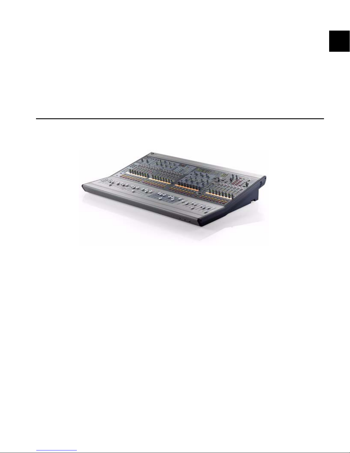
Welcome to VENUE™ Profile, part of Digidesign’s modular VENUE live sound environment. VENUE Profile systems offer an intuitive console layout, a flexible I/O scheme, powerful digital processing, and expansion options for integrated Pro Tools recording and artist-controlled monitor mixing.
VENUE Profile Systems and Features
The VENUE Profile console can be used with one Mix Rack, or with FOH Rack and Stage Rack units.
Figure 1. VENUE Profile console
Profile Console Control Features
• 24 bankable input channel strips, each with a touch-sensitive fader, one multi-purpose assignable rotary encoder,
solo, mute and select controls
• Built-In High-Pass Filter, Dynamics a n d EQ pro ces sors on
each input channel strip
• Level meters on each input channel strip
• Assignable Channel section with dedicated Bus Assign,
Aux Send, Direct Output, EQ and Dynamics controls.
• 8 multi-purpose Output faders strips, each with a
touch-sensitive fader, one multi-purpose encoder, solo,
mute and select controls
•1 Mains fader
• Up to 24 31-band Graphic EQs available for Outputs
• Main Busses configurable as Left–Center–Right or
Left–Right+Mono
Console I/O
• Talkback mic input, with gain and phantom power
• Headphone output
• USB inputs for keyboard, mouse/trackball, iLok USB
Smart Keys, and USB storage devices
• VGA monitor output for software screen display
• GPI ports (DB-25) providing 8 GPI inputs and 8 GPI outputs
Chapter 1: Introduction to VENUE Profile 3
Page 14

VENUE Mix Rack System
VENUE Profile System
VENUE Profile Console with Mix Rack
Mix Rack Features
The Mix Rack provides all stage and mix position I/O for
VENUE Mix Rack systems.
Stage I/O
• 48 inputs with mic preamps. Each fully recallable input
provides phantom power and input gain.
• 16 line level analog outputs (expandable up to 32) to
connect to mains and monitors.
FOH I/O
• 8 pairs of analog I/O for hardware inserts, or for input
and output of line-level material from the mix position.
• Analog and digital (AES or S/PDIF) 2-Track inputs and
outputs.
• Com mic input, with gain control and phantom power.
• Monitor outputs for mix position near field monitors.
Synchronization and Control I/O
• MIDI In and Out ports, providing 16 channels of MIDI
input and 16 channels of MIDI output.
• Word clock I/O for digital clock synchronization.
• USB 2.0 ports for USB disks, iLoks, and other USB devices.
• 100 BaseT Ethernet (ECx) port for remote control.
CPU, DSP, and System Drives
Mix Rack houses the CPU, DSP, hard drive and CD-ROM drive
th a t run t he V E NUE D-S h ow soft w are on y our VEN UE s y stem.
System software is installed at the factory. The CD-ROM drive
lets you update or restore your system software, and install
compatible plug-ins from their installer discs. A standard
Mix Rack includes two Mix Engine cards providing DSP for
plug-ins. You can add one additional Mix Engine card, for a
maximum of three.
Redundant Power Supply Units (PSUs)
Each Mix Rack comes with two universal (100V to 240V nominal, 50–60 Hz) PSUs with auto redundant failover and LED
status indication.
VENUE Profile Console with FOH Rack and Stage Rack
FOH Rack Features
The FOH Rack is used with one or more Stage Racks, and provides mix position I/O for VENUE Profile systems.
Audio I/O
• 8 pairs of analog I/O for hardware inserts, or for input
and output of line-level material from the mix position.
• Analog and digital (AES or S/PDIF) 2-Track inputs and
outputs.
• Monitor outputs for mix position near field monitors.
• Intercom mic input
Synchronization and Control I/O
• MIDI In and Out ports, providing 16 channels of MIDI
input and 16 channels of MIDI output.
• Word clock I/O for digital clock synchronization.
• USB 2.0 ports for USB disks, iLoks, and other USB devices.
• 100 BaseT Ethernet (ECx) port for Ethernet-based remote
control.
• Snake connectors to enable primary and redundant (if
applicable) connection to the VENUE Stage Rack.
CPU, DSP, and System Drives
FOH Rack houses the CPU, DSP, hard drive and CD-ROM drive
that run the VENUE D-Show software on your VENUE system.
System software is installed at the factory. The CD-ROM drive
lets you update or restore your system software, and install
compatible plug-ins from their installer discs. A standard
FOH Rack includes three Mix Engine cards, which provide
DSP for plug-ins and mixing. You can add up to two additional Mix Engine cards, up to a maximum of five.
Redundant Power Supply Units (PSUs)
Each FOH Rack comes with two universal (100V to 240V nominal, 50–60 Hz) PSUs with auto redundant failover and LED
status indication.
VENUE Profile Guide4
Page 15

Stage Rack Features
Additional Required Components
Stage Racks are used with an FOH Rack, and provide all stage
audio I/O for VENUE Profile systems. Up to two Stage Racks
can be used simultaneously, supporting up to 96 total inputs.
Audio I/O
• 48 inputs with remotely controllable mic preamps and
individually selectable phantom power.
• 8 analog output channels; expandable up to 48 analog or
digital outputs per Stage Rack.
Synchronization and Control I/O
• Snake connectors to enable primary and redundant (if
applicable) connection to a VENUE FOH Rack.
System Components
Included Components
All VENUE Profile systems include the following:
• VENUE Profile console
• Two (2) IEC power cables
• Monitor mount for VGA screen (screen not included)
• Trackball mount (trackball not included)
• VENUE Mouse Pad
• VENUE Profile Guide
• Two (2) console lights
•Protective Dust Cover
• Rack(s) (see next)
The following components must be purchased separately:
• Video Display (15-inch or greater flat-panel VGA display
recommended; 1024x768 minimum resolution). VGA and
DVI supported.
• USB keyboard and trackball/mouse (Windows compatible)
Digital Snake Cable (VENUE Profile Systems Only)
• The connection between FOH Rack and Stage Rack requires
a Digital Snake cable. This cable can be purchased directly
from Digidesign or assembled by your preferred vendor.
Optional Components
The following components are optional, and must be
purchased separately:
• USB flash disk (or other portable USB storage device for
transfer of Show data; 512 MB or larger recommended)
• Near-field monitor speakers for mix position monitoring
• Headphones with 1/4-inch jack
• Dynamic or condenser microphone and XLR mic cable
(for Talkback)
• Footswitches (up to 2)
• MIDI cables (for connecting external MIDI devices)
• BNC cables (for connecting Word clock between the
VENUE system and external digital devices)
• 25-pin D-Sub cables (for connecting to GPI devices)
VENUE Profile Expansion Options
Racks, Software CDs, iLoks, and Cables
Each Mix Rack or FOH Rack includes:
• System Restore CD
• ECx Ethernet Control Software Installer CD
• Standalone Software Installer CD
• iLok USB Smart Key (for storing plug-in authorizations)
• Plug-in installer discs (if any) with pre-authorized iLok
• Two (2) IEC power cables
• One FOH Link cable for connection to a VENUE console
Each Stage Rack includes:
• Two (2) IEC power cables
The following options can be added to VENUE Profile systems.
For details on all VENUE systems and options, visit the Digidesign website (www.digidesign.com).
Mix Rack Options
I/O Options
Each Mix Rack supports a maximum of 3 input cards and 2
output cards for a total of up to 48 inputs and up to 32 outputs. Mix Rack I/O options include:
AI16 Analog Mic/Line Input Card that provides 16 analog
mic/line level inputs
AO16 Analog Output Card that provides 16 analog line level
outputs
XO16 Analog and Digital Output Card that provides 8 analog
line level outputs, and 8 AES digital outputs.
AT16 A-Net Output Card that provides 16 channels of A-Net
output compatible with Aviom® Personal Mixers and other
Pro16™ Series devices.
Chapter 1: Introduction to VENUE Profile 5
Page 16

DSP Expansion Options
Stage Rack Options
An additional Mix Engine card can be added to the Mix Rack
(up to a maximum of three Mix Engine cards) to increase the
amount of DSP available for mixing and plug-in processing.
Record and Playback Options
FWx Record/Playback Option This FireWire-based option lets
you record or play back up to 18 channels of audio directly
from Mix Rack with a Pro Tools LE™ system.
HDx Record/Playback Option This option lets you record or
play back up to 64 channels of audio directly from Mix Rack
with a Pro Tools|HD® system.
Only a single HDx Card can be installed in a Mix Rack.
Only one Record and Playback Option can be installed at
any one time (either HDx or FWx).
FOH Rack Options
I/O Options
An FOH Input/Output (IOx) card can be added to the
FOH Rack, providing an additional 8 channels of analog I/O
and 8 channels of AES/EBU Digital I/O.
I/O Options
Each Stage Rack supports up to 6 input cards and 6 output
cards, for a total of up to 48 inputs and up to 48 outputs (analog or digital). Stage Rack I/O options include the following:
SRI Analog Mic/Line Input Card that provides 8 analog
mic/line level inputs
SRO Analog Output Card that provides 8 analog line level outputs
DSI Digital Output Card that provides 8 digital outputs (AES
or ADAT)
DSO Digital Output Card that provides 8 digital outputs (AES
or ADAT)
Personal Q The Personal Q (PQ) monitoring system lets performers adjust their monitor mix being sent from VENUE using a PQ Controller unit. The Stage rack can accommodate
one PQ Rack and up to 8 PQ Controllers.
A-Net Output ANO A-Net Output Card that provides 16 channels of A-Net output compatible with Aviom® Pro16™ Series
devices for personal monitoring.
DSP Expansion Options
Additional Mix Engine cards can be added to the FOH Rack
(up to a maximum of 5 Mix Engine cards) for increased mixing
and plug-in processing capacity.
Snake Card Expansion
Adding a second Snake Card to the FOH Rack lets you add a
second Stage Rack to your VENUE system, giving you a total of
up to 96 channels of Stage I/O.
Record and Playback Options
FWx Record/Playback Option This FireWire-based option lets
you record or play back up to 18 channels of audio with a
Pro Tools LE™ system.
HDx Record/Playback Option This option lets you record or
play back up to 128 channels of audio directly with a
Pro Tools|HD® system.
Additional Stage Rack
A second Stage Rack can be added for a total of up to 96 inputs
or up to 96 outputs. (A second Stage Rack requires an additional Snake card be installed in the FOH Rack.)
Redundant Digital Snake
An optional redundant Digital Snake cable can be run between the FOH Rack and each Stage Rack. This redundant
Snake automatically takes over communication if the primary
Snake fails.
VENUE Profile does not support console expansion via
D-Show Sidecar units.
VENUE Profile Guide6
Page 17

Operational Requirements
Connection Requirements
Temperature and Ventilation
VENUE units should be operated away from heat sources and
with adequate ventilation.
Hardware monitoring and automatic warnings are provided
for temperature, power and other factors. For more information, see “Hardware Monitoring Window” on page 234.
Storage
VENUE Profile should be stored and transported at temperatures not lower than 0 degrees F (–18 degrees C) and not
exceeding 140 degrees F (60 degrees C).
Operation
VENUE Profile should be operated at temperatures not lower
than 40 degrees F (4 degrees C) and not exceeding
104 degrees F (40 degrees C).
During operation, the front and back panels of VENUE Profile
should be exposed to ambient air. Do not block the ventilation holes on any VENUE system component.
Do not operate in direct sunlight or at extreme ambient
temperatures.
Water and Moisture
Power Connections
Each VENUE component requires its own power connection
for primary and redundant power (if applicable).
Make sure your power source is correctly rated for the number
of units you are connecting. A surge-protected power source
(not included) is highly recommended.
VENUE Profile power supplies are capable of operating at 50 to
60 Hz across a voltage range of 100 to 240 V.
FOH Link Connection
Connection between the VENUE Profile console and the
Mix Rack or FOH Rack is made with the provided FOH Link
cable. For replacement cables, contact Digidesign Customer
Service or your VENUE dealer.
For more information, see the VENUE FOH Rack Guide.
Audio Connections
All VENUE Profile system analog audio inputs and outputs
(except Headphones) are balanced XLR or balanced 1/4-inch
connections.
All external digital audio inputs and outputs are AES/EBU
(XLR), ADAT (Lightpipe) or S/PDIF (RCA) connections.
VENUE units should be operated away from sources of direct
moisture and should be kept clear of liquids that might spill
into the units. If condensation is present on the unit, leave the
unit to dry in ambient air for at least one hour before powering the unit on.
Humidity ranges for storage and operation
Storage humidity range 5% to 95%, non-condensing
Operating humidity range 20% to 80%, non-condensing
Cleaning and Maintenance
Use a dry cloth to clean the VENUE Profile top surface when
needed. Do not apply any cleaning solutions, spray cleaners,
or abrasives to the surface.
For more information on audio connectors and specifications, see Chapter 26, “Audio Specifications.”
Snake Connections
VENUE Mix Rack Systems
For Mix Rack, an analog multicore snake (not provided) is recommended to bring inputs from stage to the mix position,
and return outputs back to the stage for monitor and mains
amplification.
VENUE Profile Systems
Connection between the FOH Rack and the Stage Rack is made
with the Digital Snake cable (not included). Cables can be purchased directly from Digidesign or assembled by your preferred vendor. For Snake cable specifications and requirements, see the VENUE Stage Rack Guide.
Chapter 1: Introduction to VENUE Profile 7
Page 18
Registration
About www.digidesign.com
Review the enclosed Digidesign Registration Information
Card and follow the instructions on it to quickly register your
purchase online. Registering your purchase is the only way
you can be eligible to receive complimentary technical support and future upgrade offers. This is one of the most important steps you can take as a new user.
Conventions Used in This Guide
Digidesign guides use the following conventions to indicate
menu choices and key commands:
:
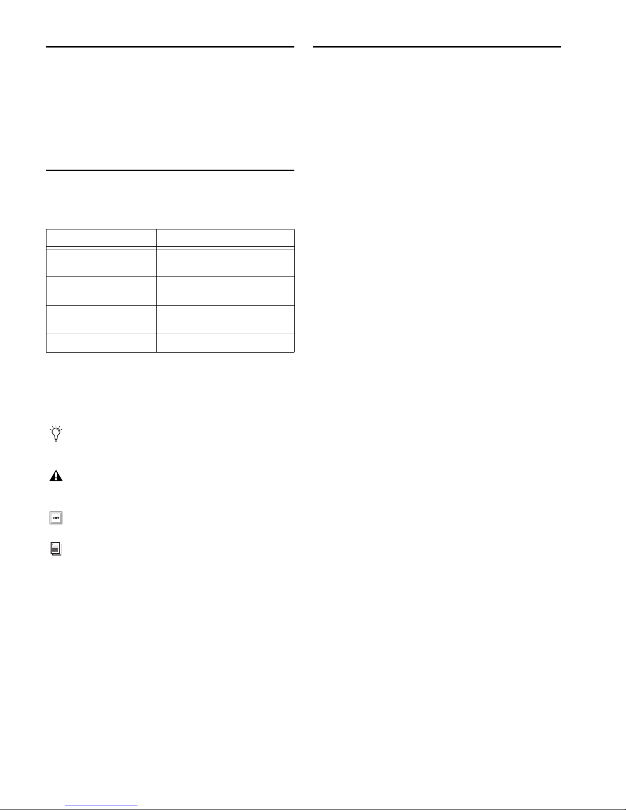
Convention Action
Options > System Click the Options tab, then click the
Control+N Hold down the Control key and press
Control-click Hold down the Control key and click
Right-click Click with the right mouse button
The names of Commands, Options, and Settings that appear
on-screen are in a different font.
The following symbols are used to highlight important
information:
User Tips are helpful hints for getting the most from your
system.
Important Notices include information that could affect
your data or the performance of your system.
System sub-tab
the N key
the mouse button
The Digidesign website (www.digidesign.com) is your best online source for information to help you get the most out of
your Pro Tools system. The following are just a few of the services and features available.
Product Registration Register your purchase online.
Support and Downloads Contact Digidesign Technical Support
or Customer Service; download software updates and the
latest online manuals; browse the Compatibility documents
for system requirements; search the online Answerbase or join
the worldwide VENUE community on the Digidesign User
Conference.
Training and Education Study on your own using courses available online or find out how you can learn in a classroom setting at a certified Pro Tools training center.
Products and Developers Learn about Digidesign products;
download demo software or learn about our Development
Partners and their plug-ins, applications, and hardware.
News and Events Get the latest news from Digidesign or sign
up for a Pro Tools demo.
Pro Tools Accelerated Videos Watch the series of free tutorial
videos. Accelerated Videos are designed to help you get up and
running with Pro Tools and its plug-ins quickly.
Live Sound Webinars Watch free tutorial videos and
VENUE-specific webinars to learn from the experts.
To learn more about these and other resources available
from Digidesign, visit the Digidesign website
(www.digidesign.com).
Shortcuts show you useful keyboard or mouse shortcuts.
Cross References point to related sections in this guide and
other Digidesign guides.
VENUE Profile Guide8
Page 19
Chapter 2: Configuring and Connecting Profile
Mounting Arm
T-bolt (2)
Locking Nut (2)
U bracket
(top)
back
front
U bracket
Mounting arm (top)
screws
Mounting plate
screws
Video monitor
U bracket
Video monitor
Mounting arm
back
front
screws
screws
The chapter shows how to connect the components of a
VENUE Mix Rack and VENUE Profile system.
Unpacking and Assembling
VENUE Profile
Remove all components from the shipping packaging.
Place the Profile console on a table or other stable surface
that leaves full access to the front and back panel connectors
and mounts.
Make sure all components are free of any bags, padding or
other materials.
Keep cables and other included items organized, making
sure to keep them with their associated component after unpacking.
Assembling the Video Monitor Mount
and Trackball Mount
Profile includes a Video Monitor Mount for your VGA monitor, and a Trackball mount for your mouse or trackball.
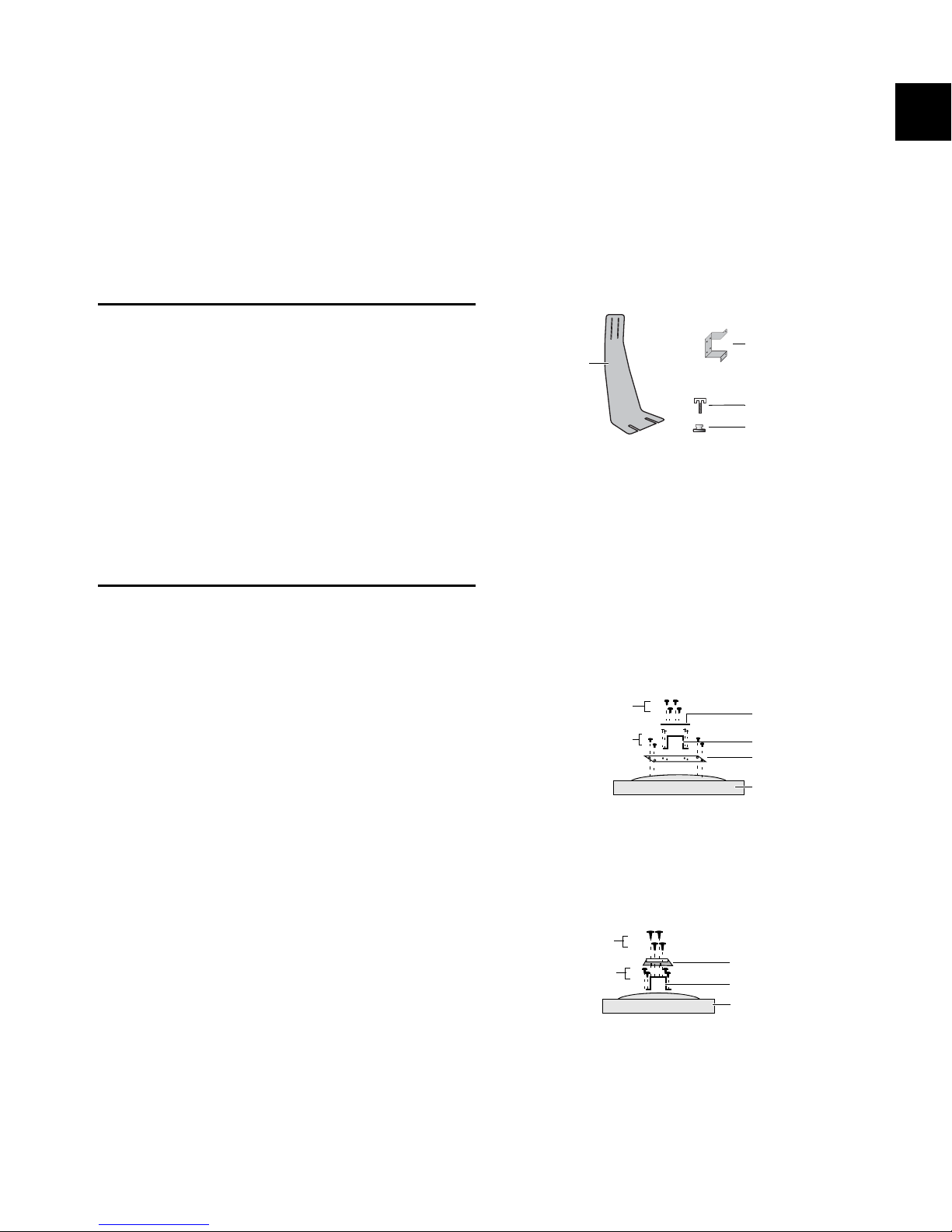
To assemble the Video Monitor Mount:
1 Remove the Video Monitor Mount components from their
packaging.
Components of the Video Monitor Mount
2 Make sure your video monitor is powered off and discon-
nected, and lay it face down on a padded table.
3 Attach your monitor to the Video Monitor Mount by doing
either of the following, as appropriate for your video monitor:
100mm (MIS-D100) Attach the U bracket to the included
mounting plate using the provided hardware. To complete the
assembly, remove the 4 mounting screws from the back of the
video monitor, line up the holes of the mounting plate, and
use the screws you removed to secure the plate to the back of
your monitor.
Assembling the Video Monitor Mount
The Video Monitor Mount is assembled by attaching a flat
panel VGA monitor to the mounting arm. Both 100mm and
75mm VESA (FDMI) video mounting standards are supported.
Assembling the Video Monitor Mount requires the following
items:
• A VGA flat panel display with 100mm or 75mm mounting compatibility
• A medium sized Phillips screwdriver
• A table or similar clear, flat area with a towel or other padded surface (big enough to safely lay your video monitor
face down)
Attaching a 100mm VGA monitor to the mounting plate, U bracket and
mounting arm, viewed from the top edge of the monitor
75mm (MIS-D 75) Use the included U bracket. Remove the appropriate screws from the back of your monitor and use them
to secure the U bracket to the back of the monitor.
Attaching a 75 VGA monitor to the U bracket and mounting arm, viewed
from the top edge of the monitor
Chapter 2: Configuring and Connecting Profile 9
Page 20
4 Hold the mounting arm face down so that the narrow (top)
Video Mount slot
end is against the back of the U bracket. Make sure the arm is
facing the correct way, and attach the arm to the U bracket using the four screws provided. Make sure all screws are tightened securely.
Attaching the Video Monitor Mount the First Time
To attach the Video Monitor Mount to the console:
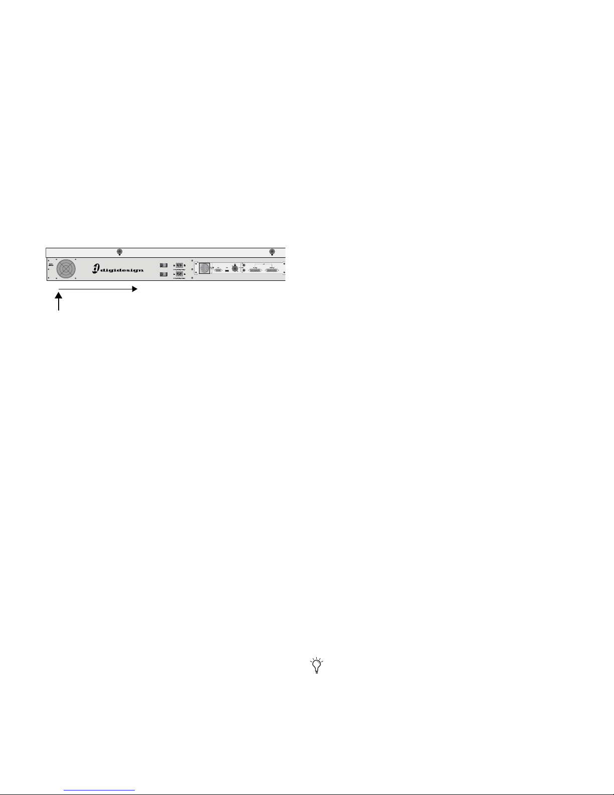
1 From the back of the console, locate the Video Mount slot
below the edge of the outermost back panel extrusion.
2 Take one of the T-bolts included with the Video Mount and
insert it into the wider opening at the far left end of the Video
Mount slot. Slide the T-bolt to the right along the slot until it
stays in the track.
Location of the Video Mount slot
3 Take the second T-bolt, insert it into the opening at the left
and slide it to be a few inches away from the first T-bolt.
4 Take the two silver lock nuts (thumb nuts) and thread them
loosely onto the T-bolts (do not tighten them).
Using the Assembled Video Monitor Mount
To remove the Video Monitor Mount:
1 Stand at the back of the console.
2 Holding the VGA screen in one hand, loosen the lock nuts
that secure the Video Monitor Mount to the console.
3 Slide the Video Monitor Mount straight back off the T-bolts.
4 Tighten the lock nuts to secure the T-bolts.
To attach the assembled Video Monitor Mount to the console:
1 Loosen the two lock nuts securing the T-bolts in place, along
the extrusion at the back of the console.
2 Position the Video Monitor Mount so that its base slots line
up with the T-bolts, slide the Video Monitor Mount into position, and tighten the lock nuts to secure the mount into place.
Assembling and Attaching the Trackball
Mount
The Trackball Mount provides a tray for your trackball or a
mouse. It can be placed anywhere along the front of the console, and accommodates left- or right-handed operation. A
small hook underneath the Trackball mount lets you hang a
pair of headphones.
Assembling the Trackball Mount
5 Pick up the assembled Video Monitor Mount and hold it at
the bottom of the VGA monitor, so you can balance the unit
with one hand.
6 Position the base of the video mount under the back panel
extrusion and feed the T-bolts through the two slots on the
front edge of the arm assembly. Loosen the lock nuts if necessary.
7 Tighten the lock nuts thumb nuts to secure the Video Mon-
itor Mount in position.
To move the monitor left or right:
Loosen the thumb nuts slightly and slide the Video Monitor
Mount to the left or right, being carefully not to twist it off either of the T-bolts. (If the mount comes off the T-bolts, simply
reattach it and resume). When in the desired position, tighten
the lock nuts.
To adjust the height of the monitor:
Loosen the screws holding the monitor or U bracket to the
mounting arm, and slide it down or up to the desired height.
Tighten all screws to secure the monitor in its new position.
To attach the Trackball Mount
1 Unpack the Trackball Mount and components from their
packaging.
2 Make sure to unplug any USB or headphone connections at
the front of the console.
3 From the front of the console, locate the slot for the Track-
ball mount (located below the extrusion).
4 Take one of the T-bolts included with the Trackball Mount
and insert it into the opening at the right end of the Trackball
Mount slot. Slide the T-bolt to the left along the slot until it is
just to the left of the front panel USB and headphone ports.
5 Take the second T-bolt, insert it into the opening at the right
and slide it into place a few inches away from the first T-bolt.
6 Take the two silver lock nuts (thumb nuts) and thread them
loosely onto the T-bolts (do not tighten them).
7 Place the Trackball Mount in position so that you can feed
the T-bolts through the two slots on the lip of the Mount.
If mounting on the right, be sure to line up the opening in
the mount with the front panel USB and Headphone ports
so they remain accessible.
VENUE Profile Guide10
8 Tighten the lock nuts to secure the assembled Trackball
Mount to the console.
Page 21

Using the Trackball Mount
The Trackball Mount can be removed and set up quickly.
Always disconnect USB and headphones from the front
panel before removing or attaching the Trackball Mount.
To remove the Trackball Mount:
1 Holding the Trackball Mount in one hand, loosen the lock
nuts that secure it to the front of the console.
2 Drop the Trackball Mount off track to remove the entire as-
sembly from the console.
3 Replace the lock nuts onto the T-bolts and tighten them
down, to secure them in place.
To attach the assembled Trackball Mount to the console:
1 Loosen the two lock nuts securing the T-bolts in place, along
the extrusion at the front of the console.
2 Position the Trackball Mount so that its base slots line up
with the T-bolts, and slide the Trackball Mount into position.
3 Tighten the lock nuts to secure the mount into place.
Chapter 2: Configuring and Connecting Profile 11
Page 22
Connections for VENUE Mix Rack Systems
FOH I/O
Stage
Stage Outputs
1–16
17–32
33–48
1–16
to
house/
mains,
monitors
zones
Inputs
analog snake
E
D
C
A
B
This section describes system and audio connections for VENUE Mix Rack systems. (For VENUE Profile systems, see “Connections
for VENUE Profile Systems” on page 15).
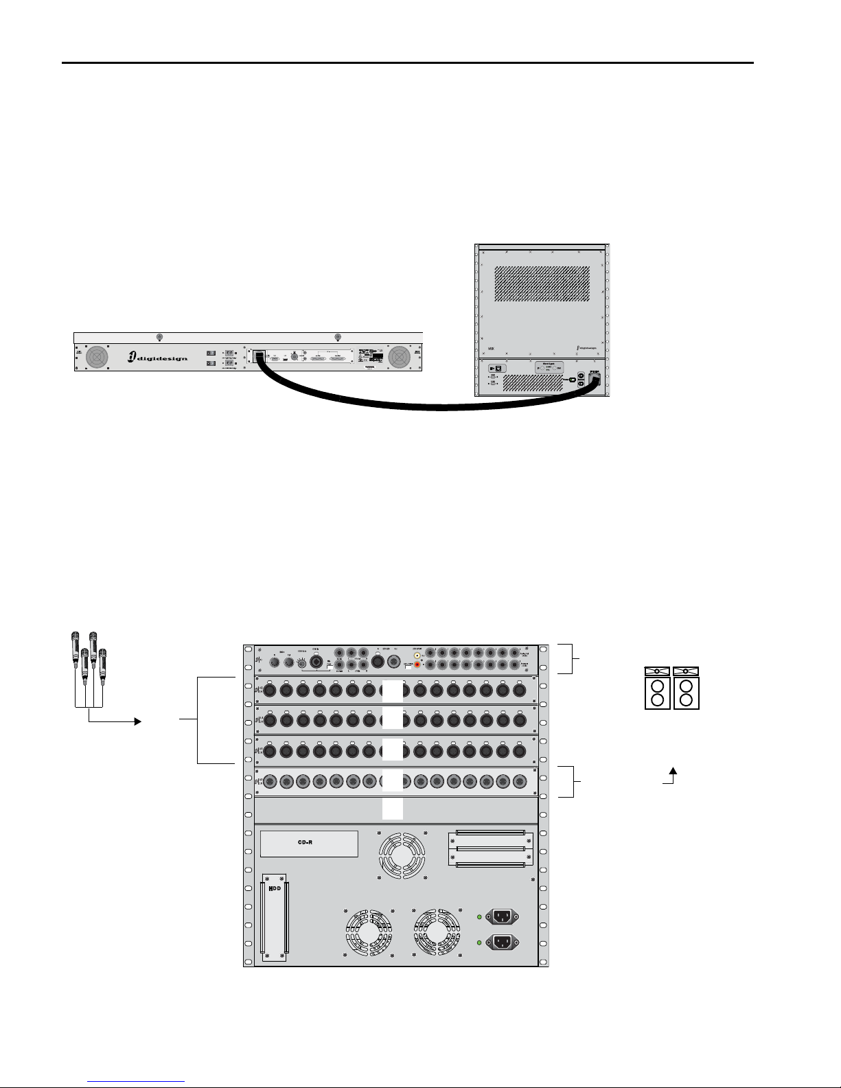
To connect the Profile console to a Mix Rack:
Connect one end of the FOH Link cable to the FOH Link port on the back panel of the Profile console. Connect the other end
of the FOH Link cable to the FOH Link port on the front panel of the Mix Rack. On each end, be sure to align the notch in the
connector housing with the slot in the plug, and to rotate the collar until the connector is fully latched.
Figure 2. FOH Link connection between Profile (left) and Mix Rack (right)
Audio Connections
Mix Rack provides 48 analog mic/line inputs, up to 32 analog line outputs, and a variety of analog and digital audio inputs and
outputs. You can use an analog multicore snake cable (not included) to carry multiple stage inputs and outputs to and from the
Mix Rack, or you can connect mics, instruments and other sources directly to Mix Rack Stage inputs, and connect Mix Rack Stage
outputs directly to the inputs on your house/mains systems, or monitor systems.
Stage I/O
Use the following sections to identify where to connect stage I/O to Mix Rack.
Figure 3. Mix Rack audio connectors and I/O slots (A–E) for stage inputs and outputs
VENUE Profile Guide12
Page 23
Stage Inputs 1–48
Analog I/O 1–8MIDI I/O
Com Mic
Com Mic Gain
Com Mic Phantom Power
Monitor
Outputs
2-Track Analog I/O
2-Track
AES/EBU I/O
2-Track
S/PDIF I/O
2-Track Digital
Format selector
Input
(Analog Mic/Line XLR Inputs)
The Stage Input section provides 48 channels of analog mic/line inputs (XLR), to connect stage input sources. Use a standard analog snake cable to run lines from the stage to the Mix Rack (analog snake cable not included). Then connect the snake to Stage
inputs 1–48. (For instructions on applying phantom power and other settings, see the guide that came with your console.)
Stage Outputs 1–16
(Analog Line XLR Outputs)
The Stage Output Section provides up to 32 channels of stage output (XLR), to connect to house/mains, monitors, additional
zones, or feeds to other devices.
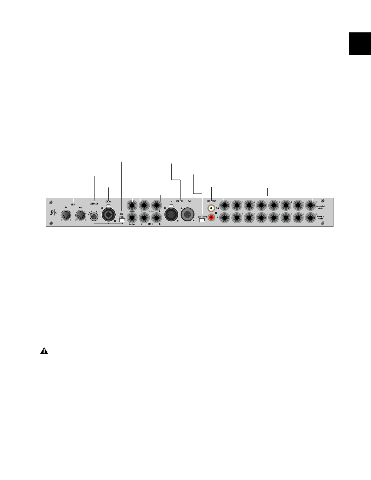
FOH I/O
The following sections describe the FOH I/O section of Mix Rack, and how to use its connectors and ports for mix position audio.
Figure 4. FOH I/O connectors on Mix Rack
MIDI I/O Ports
The MIDI In and Out Ports provide 16 channels of MIDI input
and 16 channels of MIDI output to the system. The MIDI I/O
ports are used in sending and receiving Snapshot MIDI messages, and in receiving MIDI Time Code from external devices.
Com Mic, Gain Control, and Phantom Power
The Com Mic connector and controls allow connection of a
mic, or a line level source. The Com Mic input is a female
XLR/TRS connector that accepts XLR or TRS jacks. The Gain
control operates in steps of 3 dB. Phantom power may be applied to the Com mic with the Mic Power switch.
Do not connect an intercom system directly to the Com
input, as some intercom systems use a signalling voltage
which can damage the FOH IO card.
Monitor Outputs
The Monitor Outputs are used for output to a near-field monitors or a cue mix system (not included). These are 1/4-inch
balanced TRS connectors.
2-Track Analog Inputs and Outputs
The 2-Track analog connections are used for input and output
of analog audio material. These are balanced 1/4-inch TRS
connectors.
2-Track Digital Inputs and Outputs
The 2-Track digital connections are used for input and output
of digital audio material. Stereo AES/EBU or S/PDIF I/O connectors are selectable with the AES–SPDIF switch. These connectors support 24-bit, 48 kHz digital signals. Input signals
with other sample rates are sample-rate converted to 48 kHz.
Analog I/O (1–8)
The 8 pairs of analog line inputs and outputs are used for hardware inserts, or for input and output of program material from
the mix position. These are balanced, 1/4-inch TRS connectors.
Chapter 2: Configuring and Connecting Profile 13
Page 24

Other Mix Rack Connections
(AC Power, Synchronization and Optional Connections)
AC Power Connectors
The AC Power connectors accept standard AC power cables,
for powering each of the two (redundant) internal Mix Rack
power supply units. Mix Rack power supplies are auto-power
selecting (100V to 240V, 50–60Hz) and automatically work
with a standard modular power cord when connected to an
AC receptacle in any country.
ECx Port
The ECx port lets you connect an RJ-45 Ethernet cable for remote control of the system from a laptop or tablet computer.
For more information see Chapter 30, “ECx.”
USB Ports
The USB ports on the front panel of the Mix Rack are USB 2.0
ports, letting you connect iLoks, USB key disks and other USB
devices. (An additional, secure USB port is located inside the
Mix Rack chassis as well; use this internal port to connect and
secure a pre-loaded iLok to always be available to that Mix
Rack system.)
FOH Link Connector
The FOH Link port connects the Profile console to the system
rack (Mix Rack, or FOH Rack in conjunction with one or more
Stage Racks).
Word Clock I/O
The Word Clock In and Word Clock Out ports let you integrate external digital devices with Mix Rack.
VENUE Profile Guide14
Page 25
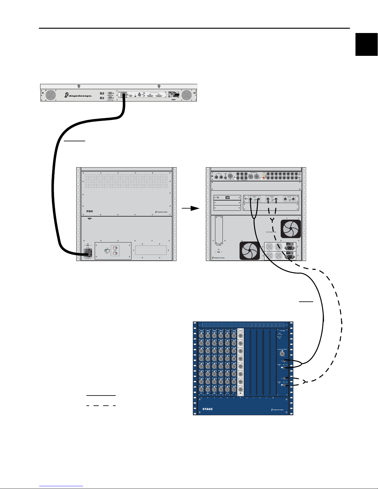
Connections for VENUE Profile Systems
VENUE Profile
FOH Rack (Front)
FOH Rack (Back)
Stage Rack (Front)
FOH Link Cable
Digital Snake Cables
Primary Snake
Redundant Snake
This section describes system and audio connections for FOH Rack and Stage Rack systems. (For VENUE Mix Rack systems, see
“Connections for VENUE Mix Rack Systems” on page 12).
Figure 5. VENUE Profile system component connections
Chapter 2: Configuring and Connecting Profile 15
Page 26
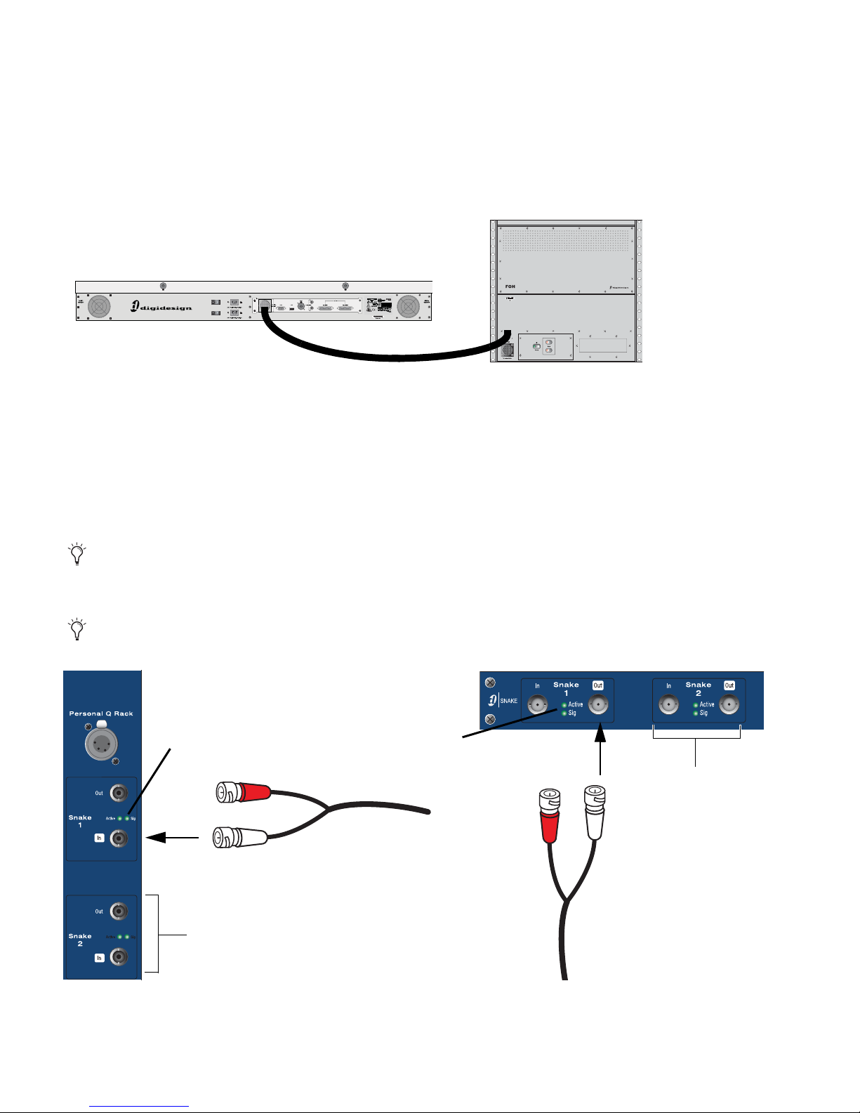
Connecting Profile to the FOH Rack
Connectors with white sleeves
Signal LED
attach to terminals with white labels
Signal LED
Redundant Snake
connects here
Redundant Snake
connects here
(Digidesign Digital Snake Cable only)
The Profile console is connected to the FOH Rack with the provided FOH Link cable.
To connect the control surface and the FOH Rack:
Connect the FOH Link cable to the FOH Link port on the back of the Profile console, and to the FOH Link port on the front
panel of the FOH Rack. On each end, be sure to align the notch in the connector housing with the slot in the plug, and to rotate
the collar until the connector is fully latched.
Figure 6. FOH Link connection between Profile (left) and FOH Rack (right)
Connecting the Stage Rack to the FOH Rack
The Stage Rack is connected to the FOH Rack with the Digital Snake cable (purchased separately).
To connect a Stage Rack to the FOH Rack:
1 Connect the send snake to the Stage 1 Out port of the Stage Rack, and to the Stage 1 In port on the FOH Rack.
2 Connect the return snake to the Stage 1 Out port on the FOH Rack, and to the Stage 1 In port on the Stage Rack.
The connectors on Digidesign’s Digital Snake cable are color coded, so that the white cable connects to the white-outlined ports.
When the system is powered up, the primary snake connection is indicated by a solid Active LED. If the Snake Signal LEDs flash,
a Snake connection could not be established.
If there are problems with the Snake connection, double check that all the BNC connectors are fully secured.
Figure 7. Detail of Digital Snake cable connection between Stage Rack (left) and FOH Rack (right)
VENUE Profile Guide16
Page 27
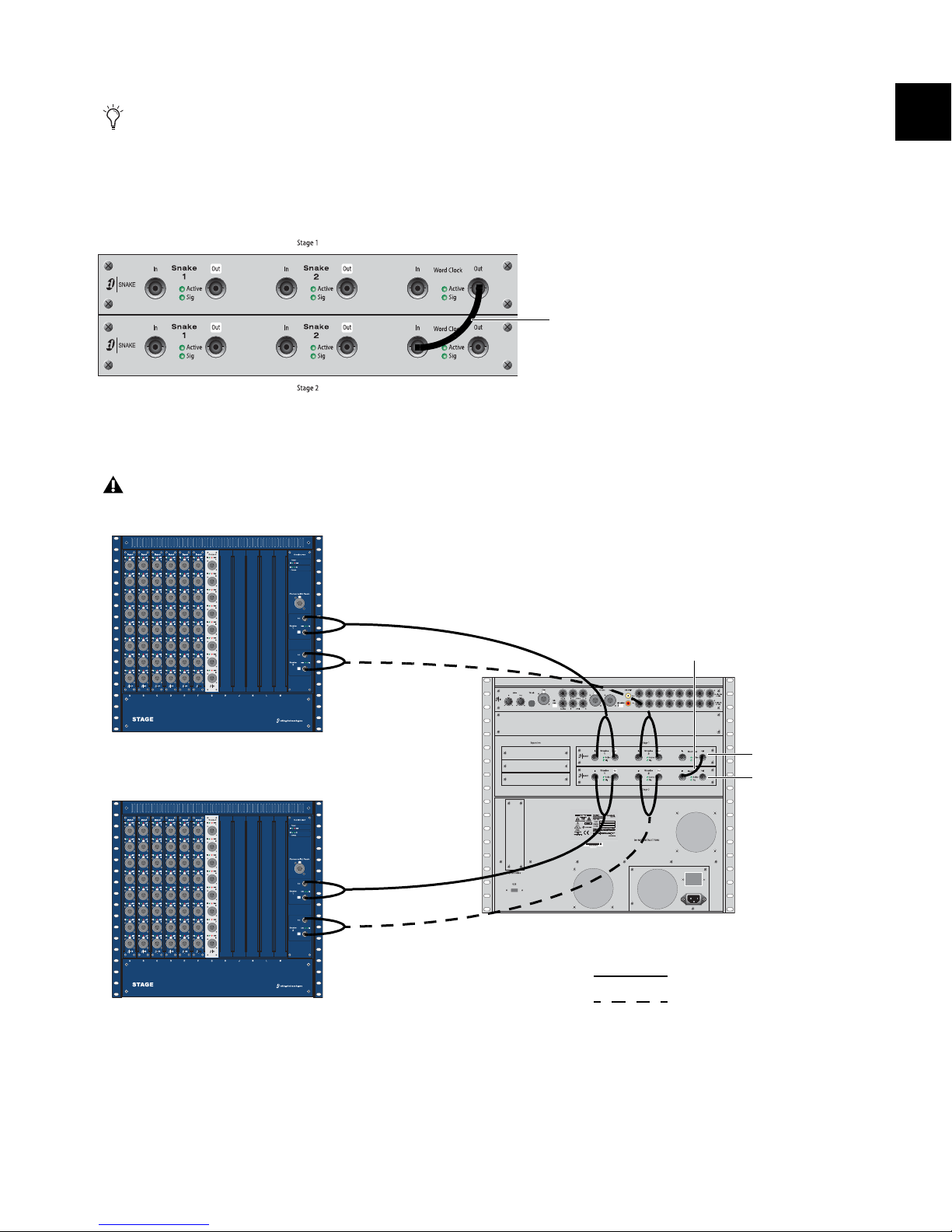
Connecting a Second Stage Rack
Word Clock BNC cable
Stage Rack 1
Stage Rack 2
Snake 2
Snake 1
Snake 1
Snake 2
FOH Rack
Snake Card 1
Snake Card 2
Primary Snake
Redundant Snake
Word Clock BNC cable
If a second Stage Rack is used, an additional Snake Card must be installed in the FOH Rack. See the Snake Card Guide for more
information.
To connect a second Stage Rack:
1 Using a BNC cable (included with the additional Snake card), connect the Word Clock Out port on the first Snake card to the
Word Clock In port on the second Snake card.
Word Clock connection between Snake cards
2 Connect the second Stage Rack to the FOH Rack with a Digital Snake cable. See “Connecting the Stage Rack to the FOH Rack”
on page 16.
The primary and redundant snake cables must be the same length.
Figure 8. Digital Snake cable and word clock connections for fully redundant system with 2 Stage Racks
Chapter 2: Configuring and Connecting Profile 17
Page 28

Audio Connections
Stage Rack Input Cards
Stage Rack Output Card
Stage Rack
Figure 9. Audio connectors on Stage Rack
Analog Audio Inputs
(Balanced Female XLR Connectors)
Connect analog mic-level or line-level input sources to any
of the input connectors on any SRI Card.
Analog Audio Outputs
(Balanced Male XLR Connectors)
Connect analog line-level output destinations (such as
power amplifiers, crossovers, or speakers) to any of the output
connectors on any SRO Card.
Digital I/O
If your Stage Rack includes a digital I/O option, see “Digital Inputs and Sample Rate Conversion” on page 22.
VENUE Profile Guide18
Page 29
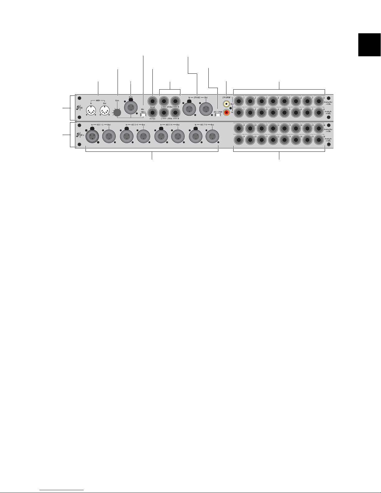
FOH Rack
Digital I/O 1–8 Analog I/O 9–16
Analog I/O 1–8MIDI I/O
Com Mic
Com Mic Gain
Com Mic Phantom Power
Monitor
Outputs
2-Track Analog I/O
2-Track
AES/EBU I/O
2-Track
S/PDIF I/O
2-Track Digital
Format selector
IO
section
IOx
section
(Optional)
Input
Figure 10. Audio connectors on FOH Rack, showing standard IO connectors (top) and optional IOx connectors (bottom)
Analog Inputs and Outputs
(Balanced 1/4-inch TRS Connectors)
Connect the analog inputs and outputs of external proces-
sors to any of these 8 analog output and input pairs. (16 inputs
and output pairs are available if the IOx option is installed.)
Connect any analog output destination (such as a recording
device or broadcast feed) to any of the outputs in this section.
Connect any analog sound sources (such as a CD player) to
any of the inputs in this section.
Digital Inputs and Outputs - IOx Option only
(AES/EBU Connectors)
Connect the two-channel digital inputs and outputs of ex-
ternal processors to any of the 4 AES/EBU digital output and
input connectors in this section.
These connectors support 24-bit, 48 kHz digital signals. In-
put signals with other sample rates are sample-rate converted
to 48 kHz.
2-Track Analog Inputs and Outputs
(Balanced 1/4-inch TRS Connectors)
Connect a 2-track analog playback source to the 2-Track
analog inputs.
Connect a 2-track analog recording device to the 2-Track
analog outputs.
2-Track Digital Inputs and Outputs
(AES/EBU and S/PDIF Connectors)
Switch the 2-Track digital I/O between AES/EBU and S/PDIF
by moving the 2-Track Digital Format selector switch to the
corresponding position. Only one of these digital formats may
be active at a time.
Connect a 2-channel digital playback source to the 2-Track
AES/EBU or S/PDIF input.
Connect a 2-channel digital recording device to the 2-Track
AES/EBU or S/PDIF output.
These connectors support 24-bit, 48 kHz digital signals. In-
put signals with other sample rates are sample-rate converted
to 48 kHz.
Monitor Outputs
(Balanced 1/4-inch TRS Connectors)
Connect a monitor amplifier or powered monitors to the
Monitor Output connectors.
The Monitor Outputs and the Headphone Output on the
front of the console are fed by the Solo/Monitor bus
Com Mic Connector
Plug a dynamic or condenser microphone, or any compati-
ble intercom system microphone into this connector.
Com Mic Gain
Turn the Com Mic knob to adjust overall Com Mic gain.
MIDI Input and Output
Connect a compatible MIDI device to the MIDI In and MIDI
Out ports. Snapshots receive and send MIDI commands, and
generate and respond to MIDI Time Code.
Word Clock
If you are integrating digital devices with your VENUE system,
make the necessary Word clock connections and settings. For
details, see “Synchronizing External Digital Source Devices”
on page 23.
Chapter 2: Configuring and Connecting Profile 19
Page 30
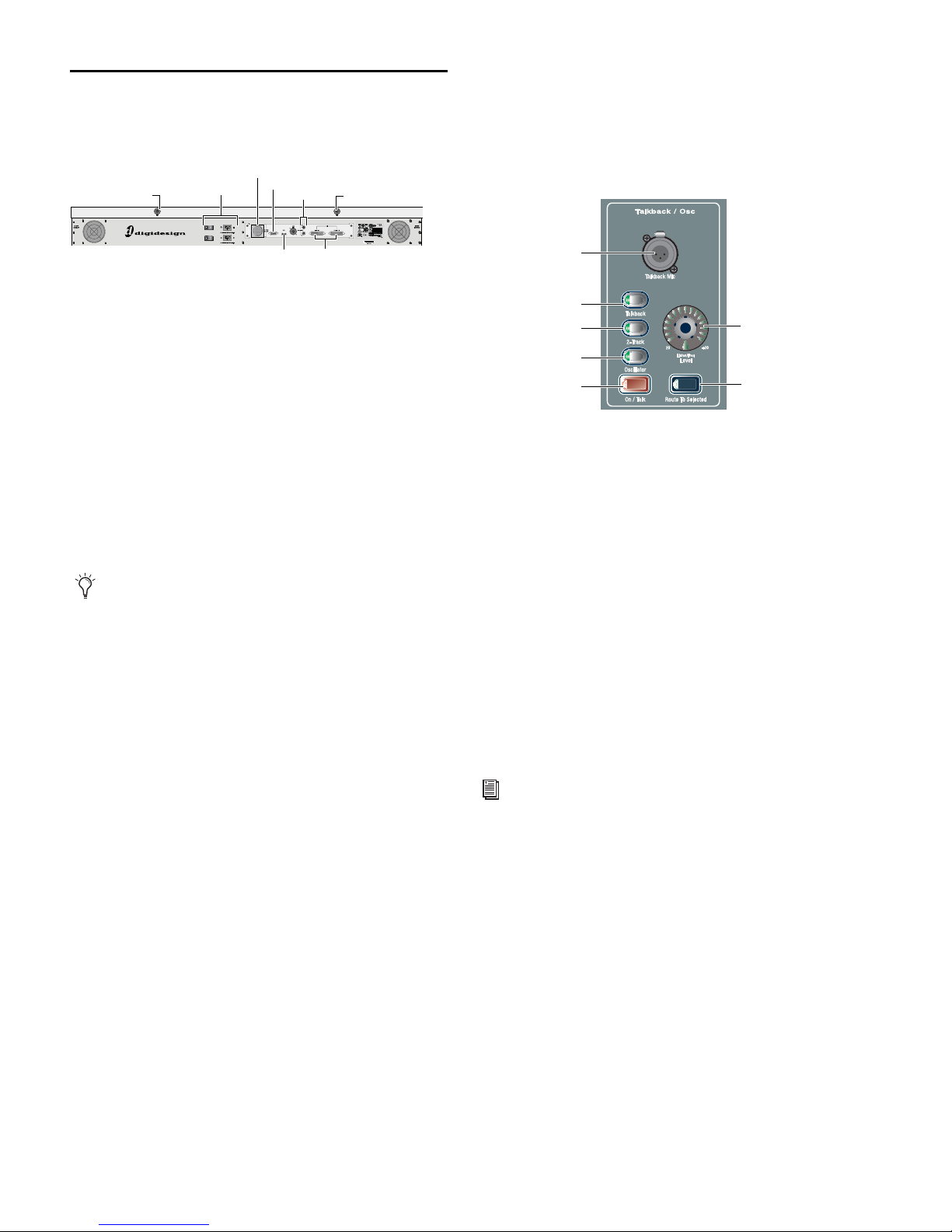
Profile Console Connections
FOH Link
VGA
Footswitch
GPIUSB
Console Lights
Power
Console Lights
Talkback Mic
Talkback level
connector
Route to
Selected
Talkback Mic
On/Talk switch
2-Track switch
Oscillator switch
Talkback switch
connector
This section describes the ports and connectors on the VENUE
Profile console. Most connectors are on the Profile back panel.
VENUE Profile back panel and connectors
VGA Display
Plug a compatible VGA display into this connector.
USB Keyboard and Trackball
Plug a compatible USB keyboard and Trackball (or mouse)
into the two available USB connectors on the front the console (just below the faders for inputs 17–24).
Other USB Devices
VENUE Profile provides USB ports on the top panel (near the
meters) and on the back panel. Use these ports to connect iLok
Smart Keys, USB flash disks or other compatible USB devices.
The Profile console provides USB 1.1 ports. For best performance, use the faster USB 2.0 ports on the Mix Rack or
FOH Rack to connect USB flash disks for data transfer.
Talkback
A Talkback input (XLR) is on the top panel.
Talkback Mic Connector
Plug a dynamic or condenser mic into this connector.
Talkback microphone connector and controls
Talkback Level
The talkback gain for this connector is fixed at 20 dB.
Adjust talkback send level by pressing the Talkback switch
in the Talkback/Osc section and turning the level knob.
Talkback Switch
Activate talkback by pressing the Talkback switch.
CAN Bus
FOH Link
FOH Link connects Profile to the Mix Rack or FOH Rack. One
FOH Link cable is included with each Mix Rack and FOH Rack.
Power
Two male, 3-pin IEC power sockets with cable retaining clips
are provided, one for each of the internal power supplies. Two
standard IEC power cables are provided with each console.
Footswitch 1 and 2
Two female 1/4-inch TS footswitch jacks are provided for
switch input. Footswitches can be normally open or normally
closed, latching or momentary. Functions are assigned to
these jacks on-screen in the Options > Events page.
Console Lights
Two XLR3-F jacks to connect to the included console lights.
This XLR3-M connector is not functional.
GPI Connections
VENUE Profile provides 8 channels of GPI input and output
through separate 25-pin D-Sub connectors on the back panel.
For specifications, wiring diagrams and pinouts, see
Chapter 29, “Control Surface Reference.”
GPI Applications
GPI inputs are connected to the outputs of a variety of switching devices such as footswitches, momentary or latching
push-button switches, or logic outputs of a larger show control system. Example applications of GPI inputs include remote toggling of a console function such as Talkback, muting
a channel, or recalling a specific snapshot.
GPI outputs connect to compatible inputs found on a variety
of external devices such as LEDs, small relays, power sequencers, and logic inputs on show control systems.
VENUE Profile Guide20
Page 31

Example applications of GPI outputs include the following:
• Triggering a sound effects playback machine when a specific
snapshot is recalled.
• Lighting a tally light whenever a fader is raised above a minimum threshold.
• Flashing or lighting a custom beacon or LED as a reminder
of vital console mode, such as Solo in Place.
• Initiating power up of amplifiers and other down-stream
systems when VENUE Profile is started up or shut down.
GPI functions, as well as footswitch assignment, are managed
using the Events List in the Options > Events window. For
more information, see Chapter 22, “Events.”
Powering Up the System
Faders move when power is turned on. Before powering up
the system, make sure all fader paths are clear of obstructions.
Power up the system in the following sequence:
1 VENUE Profile console
2 Racks:
•Mix Rack
– or –
• Stage Rack, then FOH Rack
To connect GPI devices as triggering devices to Profile:
1 Connect one end of a 25-pin D-Sub cable (not included) to
the GPI IN port on the back panel of Profile.
2 Connect the other end to the appropriate GPI output port
on the external device.
To connect GPI devices to be triggered by Profile:
1 Connect one end of a 25-pin D-Sub cable to the GPI OUT
port on the back panel of Profile.
2 Connect the other end to the appropriate GPI input on the
external device.
For specifications, wiring diagrams and pinouts, see
Chapter 29, “Control Surface Reference.”
3 Any connected computers for recording/playback options
4 Audio monitoring system
Each power supply has its own power switch that must be
in the On position in order to be powered up.
Powering Down the System
Power down the system in the following sequence:
1 Audio monitoring system
2 Any connected computers for recording/playback options
3 Racks:
• FOH Rack, then Stage Rack
– or –
•Mix Rack
4 VENUE Profile console
Setting the System Clock
When you first work with a VENUE system, make sure the system clock time, date and time zone are set appropriately. The
system clock setting can affect data synchronization with portable storage devices. See “Transferring Settings, Shows and
Presets” on page 171.
The system clock time can be shown in the Status bar for constant time-of-day display. For more information, see “System
Clock” on page 61.
Changing the system clock while using a timed iLok license
(for a plug-in with a demo period, or for a plug-in rental)
may expire the plug-in authorization.
Chapter 2: Configuring and Connecting Profile 21
Page 32

Enabling a Second Stage Rack
To enable and confirm communication with the second Stage
Rack:
1 Put the system in Config mode.
Digital Inputs and Sample Rate
Conversion
This section describes how to connect and clock external digital devices to VENUE systems.
2 Go to the Options page and click the System tab.
3 Click Edit.
4 Select Enable Stage 2, and click Apply. The system restarts.
Enabling the second Stage Rack
5 Go to Options > Devices to view hardware status. The con-
nection to the second Stage Rack should be displayed in the
FOH Rack graphic.
Overview
The types of digital I/O and connectivity available varies depending on your system components and their configuration:
Mix Rack The VENUE Mix Rack provides a pair of digital (AES)
2-Track inputs and outputs. The Mix Rack can also be expanded to include an XO16 card, to add 8 channels of analog
output and 8 channels of digital (AES) output. Mix Rack also
provides Word clock I/O.
FOH Rack VENUE FOH Racks provide numerous digital inputs
and outputs, which can be expanded further by adding an IOx
card. FOH Rack also provides Word clock I/O.
Stage Rack VENUE Stage Racks can be expanded by adding a
DSI Digital Input card to add 8 channels of digital (AES or
ADAT) input, and by adding a DSO Digital Output card for 8
channels of digital (AES or ADAT) output. DSI cards also provide Word clock I/O.
VENUE digital I/O (such as the DSI card) operates at the
VENUE system sample rate of 48 kHz. The DSI card provides
auto-detection and sample rate conversion on input, letting
you connect a wide variety of digital sources without having
to be concerned with synchronization and clock connections.
Detail of Devices page showing connection to second Stage Rack
The second Stage Rack must be enabled for the Devices tab
to display the correct number of input and output cards in
that unit.
Sample Rate Conversion Latency
When sample rate conversion is enabled on DSI or other
VENUE digital inputs, input signal paths will incur a small
amount of latency. The following table illustrates the sample
rate conversion processing delay at various sample rates.
Minimum Additional Latency due to Sample Rate Conversion
External Sample Rate SRC Process Delay
32 kHz 1.50 ms
44.1 kHz 1.09 ms
48 kHz 1.00 ms
88.2 kHz 0.848 ms
96 kHz 0.833 ms
Sample rate conversion (SRC) can also be disabled (DSI card
only). This provides the lowest possible input path latency,
but requires that care be taken to synchronize the source and
other devices accordingly (see “Synchronizing External Digital Source Devices” on page 23).
VENUE Profile Guide22
Page 33

Even when SRC is disabled, connecting an unsynchronized
BNC
Stage Rack
DSI card
DSI Word Clock Out
Set device to slave to
incoming Word Clock
External digital device
AES (or ADAT)
BNC
Stage Rack
DSI card
FOH Rack
Set device to slave to
incoming Word Clock
External digital device
AES (or ADAT)
Word Clock Out
device to a DSI input causes SRC to automatically be re-enabled. This lets audio continue passing without interruption.
To manually disable Sample Rate Conversion:
1 Click the Inputs tab and navigate to the input channel being
fed from a DSI input.
2 Click the channel’s SRC OFF button until it turns off.
Auto-Detecting
The DSI card automatically detects whether an external device
connected to a DSI input is synchronized to the VENUE system. Here, “synchronized” means the device is running at
48 kHz, and is clocked to the VENUE system (see “Synchronizing External Digital Source Devices” on page 23). In this case,
no sample rate conversion is required on input.
If the external device is not synchronized, the VENUE system
automatically engages sample rate conversion on those inputs
even if sample rate conversion was manually defeated. The SRC
LED flashes on the DSI card, and a message appears on-screen
to indicate this condition.
SRC status is not affected when an input channel is reset
via right-click “Reset Strip” commands.
Using Word Clock Out from the Stage Rack
(Stage Rack with DSI Card)
Connect the Word Clock Out provided on the DSI card to
the corresponding digital device. Set the external device to
slave to the incoming word clock signal.
Using word clock from the DSI card to clock an external device
Using Word Clock Out from the FOH Rack
(Stage Rack with DSI Card)
Connect the Word Clock Out on the FOH Rack to the corre-
sponding digital device. Set the external device to slave to the
incoming word clock signal.
Sample rate conversion can be enabled or disabled manually
for digital inputs, as follows:
When using AES inputs on DSI cards, sample rate conver-
sion can be enabled or disabled for each pair of inputs.
When using ADAT (Optical) inputs on DSI cards, sample
rate conversion can be enabled or disabled for all 8 channels.
Enabling or disabling SRC on any ADAT channel enables or
disables all other ADAT channels on that DSI card.
Switching input Source between AES and ADAT (Optical)
ports retains the last sample rate conversion setting for that
input type and channel (AES channel pairs only).
Synchronizing External Digital Source
Devices
When an external device is running at 48 kHz and clocked to
VENUE, disabling sample rate conversion on those digital inputs provides the lowest possible input path latency.
Using word clock from the FOH Rack to clock an external device
Automatic detection and enabling of sample rate conversion is always in effect and will engage sample rate conversion whenever a mismatch is detected at a DSI input, even
when sample rate conversion is manually defeated for that
input.
Before sample rate conversion is defeated on any input con-
nected to a digital source, that source device must be synchronized (clocked) at 48 kHz in one of the following ways:
Chapter 2: Configuring and Connecting Profile 23
Page 34

Using Digital Audio Outputs from the VENUE
Stage Rack
DSI card
FOH Rack
Set device to slave to
incoming digital signal
External digital device
AES (or ADAT)
DSO card
AES (or ADAT)
from DSO card
-or-
any FOH Rack
digital audio output
BNC
Stage Rack
DSI card
FOH Rack
Set device to slave to
incoming Word Clock
External digital device
AES (or ADAT)
Word Clock In
House clock source
BNC
System
Connect any digital output to a digital input of the external
device: Use digital outputs on the Mix Rack (if the system also
includes an XO16 card), Stage Rack (if the system also includes
a DSO card) or any digital output on the FOH Rack. Set the external device to slave to its digital input.
Using a digital output to provide clock to an external device
Using House Clock
Connect a “house” or other external master clock signal to
the Word Clock In on the FOH Rack. Distribute the same
house clock to the external digital device, and set it to slave to
the incoming house word clock signal.
Using a distributed house (master) to clock a VENUE system and an
external device
VENUE Profile Guide24
Page 35

Part II: System Description
Page 36

Page 37

Chapter 3: VENUE Profile Control Overview
Global
A Input Channels 1–16 and 17–24
A A
B
Bus Output Mains
Meters
B Assignable Channel Sections (ACS)
C Output Masters Section
C
D
D Master and Global Controls
Modifiers
VENUE Profile Top Panel
The following figure identifies the main sections of the Profile console:
Figure 11. VENUE Profile console
Profile provides 24 bankable input channel strips in Input Channel sections, an Assignable Channel Section (ACS), eight bankable
output channel strips plus a Mains fader in the Output Masters section, as well as global controls and comprehensive metering.
Chapter 3: VENUE Profile Control Overview 27
Page 38

Input Channels and Faders
Encoder Switches
Clip and Safe LEDs
Bus Assign LEDs
Meters
Encoders and LEDs
LCD Display
Select
Solo
Mute
Faders 1–8
Bank A/B/C/D FX Returns/GEQ
Input sections provide 24 faders and other controls for Input Channel and FX Returns. Input channels are arranged in two sections: Input channel strips 1–16 are to the left of the Output Master Section, while Input strips 17–24 are to the right. Additional
channels are banked to the 24 faders using the Bank A, B, C and D switches. All 24 input channels bank together.
Input faders 1–16 can also be assigned to control FX Returns 1–8 or 9–16, or the output EQ (graphic EQ).
Each input channel strip includes a channel fader, channel Select, Mute and Solo switches, a rotary encoder, LCD display area and
meters for channel level and gain reduction. The encoders and associated assignment switches access Gain, Pan, HPF, Compressor
and Gate thresholds and Aux sends. Each bank of eight input channels provides a two-row LCD display that shows channel
name, parameter names, values and other data as appropriate for the current action.
Additional input parameters are controlled by selecting one or more channels to make them the target of the ACS.
Figure 12. Input controls (Input Channels 1–8 shown)
Clip LED
The Bank Clip Indicator lights to indicate a meter clip on an
Input Channel or FX Return at the corresponding position in
an alternate bank of channels. This indicator obeys the same
clipping threshold display rules as the Input Channel meters
(as set in the Options > Interaction page). It gives you an indication of extreme signal level in a currently hidden
(“off-bank”) layer.
VENUE Profile Guide28
Safe LED
Automation Safe, Solo Safe, or Bank Safe
The Safe LED indicates either an input strip’s Automation safe
status, Solo safe status, or Bank Safe status, depending on the
current Input Safe Switch setting. See “Input Safe Switches” on
page 62
Auto Safe Mode If the Safe LED is lit, the channel will not respond to Snapshot-driven changes. If the LED is off, that
channel will respond to any applicable changes driven by
Snapshots (subject to the current Recall Safe settings, if Recall
Safe is enabled).
Page 39

Solo Safe Mode If the Safe LED is flashing, the channel will
LR
C/M
1–8
Stereo Pan
Comp/Lim
Input Level
EQ In/Out
Stereo
Gate LED
Gain Reduction
not respond to solo commands (it will not be muted if another
channel’s solo button is pressed). If the LED is off, that channel will be silenced when soloing another channel.
Input Channel Metering
Each Input Channel provides a gain reduction meter, input
level meter, and LEDs to indicate EQ, Gate, and stereo status.
Bank Safe Mode If the Safe LED is flashing rapidly, the channel remains in place on the top fader layer when a different
Bank (A–D) is selected (it will be unlinked from console banking). If the LED is off, the channel follows banking.
Pressing a channel Safe switch for the Selected Channel toggles the current state of that channel.
Bus Assignment Indicators
These green LEDs indicate Group bus assignments, and can
also show VCA or Mute Group membership for each channel.
By default, Group bus assignment is displayed.
Bus Assign indicator LEDs on an Input Channel
Group Bus Assignment
If the LR LED is lit, the input channel feeds the Left and
Right Main busses in either L–R or L–C–R panning mode (regardless of the Stereo Pan LED status).
If the C/M LED is lit, the input channel feeds the C (center)
bus from the pan in L–C–R mode, or the M (mono) bus before
the pan. Stereo channels are summed to the mono bus.
If a bus LED (1–8) is lit, the channel is feeding the corre-
sponding Group(s). If an LED is off, the channel is not feeding
that Group. The Bus Indicators can also show VCA and Mute
Group membership.
Use the Bus Assign switches to route and assign the currently selected channels to busses (see “Assignable Channel
Section” on page 32).
VCA Membership
When VCA Show Members mode is enabled, Group indica-
tors flash to indicate VCA membership.
Comp Gain Reduction Meter
A 3-segment meter displays gain reduction for the channel
compressor/limiter. Green LEDs are used for all segments.
Input channel meters and LEDs
Input Level Meter
A 6-segment meter displays input level and indicates clipping.
Bi-color LEDs are used for all segments, as shown in the following table. Clipping is indicated when all LEDs light red.
For meter scales, see “Channel Meters” on page 113.
EQ Status LED
A single red LED indicates EQ In/Out status as shown in the
following table.
Color EQ Status
(none) Not in circuit
Red In circuit
Stereo Channel LED
A single yellow LED indicates a stereo input channel. The stereo channel LED flashes if a 10 dB or greater offset is detected
between left and right inputs.
Color Channel Status
(none) Mono
Yellow Stereo
Mute Groups
When the Mute Groups Show Members switch is pressed,
the Group indicators flash to indicate Mute Group assignments. A flashing LED indicates that the channel is assigned
to the corresponding Mute Group (1–8).
Stereo Pan LED
This LED indicates when the channel is assigned to a stereo
Groups bus.
Gate Status LED
A single bi-color LED shows the current Expander or Gate status. For LED scales, see “Gate Status LED” on page 113.
Chapter 3: VENUE Profile Control Overview 29
Page 40

Input Encoders and Assignment Controls
Encoder Assignment Switches
Encoders
LCD
Pan
Each input channel features one assignable input encoder that
can be assigned to control a variety of channel functions such
as input gain, HPF corner frequency, pan/balance/width, and
specific parameters of built-in Dynamics processes.
The Encoder Assignment switches, located to the left of the
row of encoders, determine the function of the encoders on
Input Channels. The LCD displays the current function (see
“Input Channel LCD Display” on page 31).
Input encoders, assignment switches, and LCD
Rotary and Switch Functionality
The rotary encoders on VENUE consoles are dual-function
controls that provide rotary and switch functions. In addition
to adjusting parameters by turning the encoder, you can toggle parameters (such as taking the high-pass filter in or out of
circuit) by pressing the encoder knob.
Encoder LEDs
Two types of LEDs surround each encoder:
The LED ring around the encoder displays the relative posi-
tion of its currently assigned parameter.
Below each encoder is an indicator LED, which indicates pa-
rameter status (in/out), default setting, or other conditions related to the current encoder function.
Switches in the Encoder section assign each of the following
parameters to the Input encoders:
Gain
Pan assigns the encoders to control channel Pan if the channel is mono, or stereo channel balance if a stereo. The indicator LED lights when the pan is at center.
Comp Thrsh
Comp Thrsh assigns the encoders to control the Threshold for
the built-in Compressor/Limiter. Pressing the encoder toggles
the effect in and out of circuit. If the LED is lit the effect is in
circuit.
Gate Thrsh
Gate Thrsh assigns the encoders to control the Threshold for
the built-in Expander/Gate. Pressing the encoder toggles the
effect in and out of circuit. If the LED is lit the effect is in circuit.
HPF
HPF assigns the encoders to control the HPF corner frequency.
Pressing the encoder toggles the built-in HPF in and out of circuit. If the LED is lit, the filter is in circuit.
Delay
The Delay switch assigns the encoders to control the amount
of delay in the channel. Pressing the encoder toggles the Delay
in and out of circuit. If the LED is lit, the delay is in circuit.
Send 1–2 to Send 15–16
These switches let you select one of two Aux sends in
odd/even pairs (Send 1–2 through Send 15–16) or Variable
Group sends in odd/even pairs (Send 1–2 through Send 7–8
only).
With mono sends, the first press of the switch selects the
odd numbered send (1, 3, 5, or 7) and the second press selects
the even numbered send (2, 4, 6, or 8). The switch lights green
for the odd-numbered selection, or yellow for the even-numbered selection.
With stereo-linked sends, the first press of the switch con-
trols level for the bus pair, and the second press controls pan
for the bus pair. The switch lights green for level control, or
yellow for pan control.
Gain assigns the encoders to control input gain according to
the range available for this input (head amp gain for analog
inputs, digital gain for digital or line inputs). Pressing and
holding the encoder initiates Gain Guess, in which the
VENUE system automatically sets a nominal input gain level
based on the incoming signal.
VENUE Profile Guide30
Pressing an encoder toggles the send on or off. When the send
level is shown on the LED ring and the se n d is off, a single LED
lights. When the send is on, all LEDs light in a clockwise sequence from the lower left to the send level.
Page 41

Flip to Faders
Source Switch
When enabled, the current encoder parameter is mapped to
the channel faders. It can still be controlled from the encoder
row, so the channel fader mirrors the setting. When Flip is engaged, all channel name display backlights turn yellow, the
same color as the flip switch. Channel name is displayed in
the upper row of the LCD, with the flipped parameter displayed in the lower row (mirroring the effect of Flip to Faders).
Flip to Faders provides a special mode when working with
stereo Aux sends. For information, see Chapter 10, “Aux
Sends and Variable Groups.”
Input Channel LCD Display
There are a total of three Input Channel LCD displays, one
each for Inputs 1–8, 9–16 and 17–24.
Each LCD provides two rows of data with six characters per
row, per input channel. The upper and lower rows let you see
more than one type of channel data simultaneously, such as
channel name in the lower row and fader dB level in the upper
row while you adjust the fader. Data display depends on the
current encoder assignment.
Input Encoder Assignments and Values
The Source switch in the Display section changes the Channel
Name display to show the source input which is feeding each
channel. For example, “S1 17” indicates the channel source is
Stage Rack 1, Input 17.
Select Switch
The Select switch on each channel is used to target the channel in the Selected Channel sections, and to include the channel in Multi-Select and Multi-Assign functions. A lit Select
switch indicates the channel is selected. The name of the currently selected channel is displayed in the Channel Name display and in the Selected Channel display. When multiple
channels are selected, the Channel Name display indicates
which channel is the ACS target.
Solo Switch
The Solo switch toggles the solo state of that channel. When
enabled, the Solo switch LED is lit. When the channel is in
Solo Safe mode, the Solo switch LED flashes. Channel Solo
latches on a momentary press, and automatically releases if
held for 2 seconds or more and released.
The current encoder assignment, parameter or value is displayed in the top row of the input displays. There are two
states the top row can be in: Parameter Value mode and Parameter Name mode.
When necessary, the display abbreviates displayed functions
as shown in the following table.
Table 4. Encoder Assignment Displays
Switch Display
Gain Input Gain
Pan Input Pan
Comp Thresh Compressor Threshold
Gate Thresh Gate Threshold
Delay Input Delay
Send (n) Aux (n) Level
Flip to Faders Aux (n) Level and Pan (stereo-linked sends
HPF Frequency
Aux (n) Pan (stereo-linked sends only)
Variable Group (n) Level
Variable Group (n) Pan (stereo-linked sends only
only)
Mute Switch
The Mute switch mutes the channel at the (pre-fader) mute
point. Channel pre-fader pickoff is post-mute.
Input Faders and Banking
Each channel fader is a 100mm motorized, touch-sensitive
fader.
The Options > Interaction screen lets you enable touch-sensitive channel selection. When enabled, touching a channel
fader automatically selects that channel and makes it the Selected Channel
The faders on the Profile console can be moved even when
they do not sense a touch. This allows use of the faders
while wearing gloves. It also lets you “throw” a fader and
have it stay where it lands, and not snap back to the point
it was last touched.
Fader Banking Controls
Bank A–D Banks the Input strips. Up to four banks (A through
D) can be used to access up to 96 inputs from the 24 Input
Channel faders. Bank A is channels 1–24, Bank B is channels
25–48, and so on.
FX Returns Banks FX Return channels 1–8 to Input faders 1–8,
or FX Returns 9–16 to Input faders 9–16.
Chapter 3: VENUE Profile Control Overview 31
Page 42

Graphic EQ Banks bands of graphic EQ to the faders. Graphic
Bank A–D
FX Returns
GEQ
1–8/9–16
800–20kHz
20–630 Hz
+48 V 20 dB Pad
Input Polarity
Input Gain
Safe
Clip LED
L–R C/Mono
Group 1–8
Stereo Pan
EQs can be used on outputs only. For more information, see
Chapter 17, “EQ.”
Input fader banking and assignment switches
Global Modifier Switches
To the left of the Bank A–D switches are the global modifier
switches. See “Global Modifier Switches” on page 39.
Assignable Channel Section
The Assignable Channel Section provides dedicated routing,
EQ, Dynamics, and insert controls for the currently selected
channel. ACS sections include the Input, Bus Assign, Direct
Out, Aux Sends and Inserts sections, the Selected Channel Meters and display, and the Dynamics and EQ sections.
The ACS sections feature a light colored background color,
and each section features a blue LED which, when lit, indicates that section applies to the selected channel.
Input
This section provides a Clip LED, and controls for phantom
power, input pad, polarity (phase), gain and safe status.
Multi-Select (Shift) Lets you select multiple input channels,
and lets you select multiple items in lists.
Default (Alt) Lets you reset a parameter, section, or channel to
default values. This switch also enables certain modes such as
Show VCA Members mode.
Fine (Ctrl) Lets you select non-adjacent items in lists, or adjust
rotary encoders with greater resolution for finer control.
User This switch is currently not implemented.
Input controls
Direct Output
The Direct Output section provides level and in/out control
for the channel direct output.
Direct Output
Bus Assigns
The Bus Assigns switches are the primary routing controls for
the currently selected channel, letting you bus it directly to
the Mains (L–R) bus or to any other mono or stereo group.
VENUE Profile Guide32
Bus assign switches
Page 43

Aux Sends
Send 1–16
Variable Groups
Aux 1–8/Aux 9–16
encoders and
LEDs
Plug-Ins 1–4
In/Out
Select
LED
Meters
LCD Display
LEDs
The Aux Sends section provides in/out and level control to
route the currently selected channel to any available mono or
stereo-linked Aux bus. The Aux Sends section is banked using
the Aux 1–8 or Aux 9–16 switches.
The Variable Groups switch accesses Variable Groups mode.
When D-Show is in Variable Groups mode, the controls for
Aux 1–2 through Aux 7–8 route to Variable Groups 1–2
through 7–8 respectively. The Variable Groups switch also automatically toggles the input encoders to Variable Groups 1–8
(instead of Auxes 1–8).
The 6-character Selected Channel display shows the name of
the currently selected channel. The Selected Channel display
temporarily reverts to a parameter display mode any time an
encoder is adjusted on the selected channel.
The Stereo LED lights solid when a stereo input or output is
targeted. The Solo LED flashes any time a channel is in PFL,
AFL or Solo in Place mode.
The dual, 10-segment, bi-color LED meters indicate input level
and clip status for the currently targeted or Soloed channel.
For Selected Channel metering scale, see “Selected Channel
Level Meters” on page 114.
Dynamics
The Dynamics section provides dedicated controls and metering for built-in and plug-in dynamics processors, including a
comprehensive set of Compressor/Limiter and Expander/Gate
controls.
Aux send controls
Insert Processing
The Insert Processing section provides controls to bypass and
select plug-ins on the currently selected channel.
Insert Processing controls
Selected Channel Meter, Display and LEDs
The Selected Channel display section include two 10-segment
Selected Channel meters, a 6-character LCD display and LEDS
for Status and Solo state.
Dynamics section and controls
See Chapter 16, “Dynamics.”
EQ
The EQ section provides dedicated controls for all built-in and
compatible plug-in EQ parameters including band in/out, frequency, Q, and mode.
EQ section and controls
Selected Channel meters, displays and LEDs
See Chapter 17, “EQ.”
Chapter 3: VENUE Profile Control Overview 33
Page 44

Output Masters
Insert mode
Output Encoders
LCD Display
Select
AFL
Mute
Faders
Output Fader Mains fader
and switches
Select Mains
Mute Mains
Multi-Assign/Show VCA Members
bank switches
The Output Masters section includes eight bankable output channel strips, each with a fader, encoder and channel switches. The
Mains fader provides master level control over the Mains (house) output.
Figure 13. Output controls
Mains Fader
The Mains fader provides a single level control for the current
Mains output.
Output Faders
The eight Output Faders control level for Aux 1–8, Aux 9–16,
Personal Q, Matrix and Group busses, and VCAs.
Output Fader Bank Switches
The Output faders and encoders are banked to the desired bus
using the Output Faders switches.
Aux 1–8 Assigns the Output Faders to Aux 1–8 levels.
Aux 9–16 Assigns the Output Faders to Aux 9–16 levels.
Personal Q’s Assigns the Output Faders to PQ mixer output
levels.
Matrixes Assigns the Output Faders to Matrix mixer output
levels.
Mute, AFL and Select Switches
Above the faders are the Mute, AFL and Select switches, which
mu te, solo, a nd selec t Auxes o r Groups a ssign ed t o the Ou tpu t
section.
Output Encoders and Display
The eight Output Encoders adjust additional Output bus controls such as Group pan, Matrix source and PQ sou rce level, as
well as plug-in parameters (when in Inserts mode).
The Output Masters LCD display is a two-row display that is
capable of showing 6 characters in each row, per output bus.
The display shows the name, parameter or value currently being controlled in the Output Masters section.
The Prev Page and Next Page switches light to indicate additional functions depending on the selected output or plug-in
parameter. When lit, pressing either switch scrolls the Output
Encoders to the previous or next output or plug-in parameters.
The Inserts Mode switch puts the encoders in Inserts mode, in
which the Output encoders select and adjust plug-ins.
Groups Assigns the Output Faders to Group levels. When in
Variable Groups mode, this switch assigns the Output Faders
to control Variable Groups.
VCAs Assigns the Output Faders to VCAs.
VENUE Profile Guide34
Page 45

Master and Global Controls
Global and master controls are located in sections with a dark
background, and include the Snapshot, View Modes, Console
Config, Mute Groups/Function, Monitoring and Talkback/Osc sections in the upper right quadrant of the control
surface. In addition, the global Modifier switches for Multi-Select, Default and Fine are located next to input faders 1–16.
Global Modifiers
The Modifiers section is located to the left of Input faders 1–8,
and provides the Multi-Select, Default, Fine and User switches.
Snapshots
The Snapshots section provides Store, Recall, Previous, Next,
and Preview mode switches, along with a Select encoder and a
6-character Snapshot LCD display.
Talkback/Osc
The controls in this section provide comprehensive and flexible communication control, including a top-mounted Talkback input (XLR), Assign switches, and level control.
Talkb a ck/ Osc
Mute Groups/Function
Provides Mute Group assignment and selection in default
Mute Groups mode, or can be switched to provide eight Function switches (F keys) in Function mode. The global Cancel
switch is also located in this section.
Snapshots
For more information, see Chapter 21, “Snapshots.”
View Modes
The View Mode switches (Inputs, Outputs, Filing, Snapshots,
Patchbay, Plug-ins) display the corresponding pages
on-screen. Pressing a View Mode switch repeatedly cycles
through the individual tabs of that page. For example, pressing the Patchbay switch once displays the Patchbay page.
Pressing Patchbay again cycles through various tabs within
the Patchbay page.
View Modes
Console Mode
The Config Mode switch toggles the system between Config
and Show modes.
Mute Groups/Function section
Mute Groups
Mute Groups let you quickly mute multiple channels at the
same time. You can create and recall up to eight Mute Groups
comprising one or more channels.
See Chapter 15, “Muting and Mute Groups.”
Function Switches
In Function mode, this section provides eight Main Function
switches. The default assignments for the first four Function
switches include Preview mode on/off (F1), Variable Groups
(F2), Copy (F3) and Paste (F4).
Function switches can be assigned to perform any number
of actions using the Events window. For more information,
see Chapter 22, “Events.”
Cancel
This switch cancels the current operation, such as Multi-Select
or Multi-Assign modes.
Console Mode
Chapter 3: VENUE Profile Control Overview 35
Page 46

Monitoring
Bus Masters Mains
The Monitoring section provides level encoders for the Monitor (near field monitors) and Headphone outputs.
Meters
The Meter section includes the following:
Monitoring controls
Monitor bus delay can be set on-screen in the Options > Busses page.
USB Port and System Status LEDs
These LEDs indicate power and system status. These controls
are located in the upper left corner of the control surface.
Top panel USB port and status LEDs
For more information, see Chapter 28, “Troubleshooting.”
Meters
Bus Output Meters
Eight Bus Output meters provide selectable metering of Output busses.
Mains
The Mains meters provide constant level indication of the
house (Mains) output.
For more information, see Chapter 13, “Metering.”
VENUE Profile Guide36
Page 47

Chapter 4: Basic Commands and Modes
Tool Tip
Cursor
Banner display Mode display
Control Overview
Most features and controls that are used during a performance
are available from both the console and on-screen. Changes
made on one are immediately reflected in the other, letting
you use almost any combination of console and screen controls to mix.
The software screen is not required in order to mix a performance, as all essential mixing controls are provided on the
console. However, the screen is essential when setting up and
configuring the system before a performance.
Software-Only Controls and Displays
Many configuration settings and options are only available
on-screen, including hardware configuration settings, busses,
plug-in installation, and system diagnostics. For more information, see “System” on page 55.
Software Screen Banner Display
The software screen provides a banner display in the lower left
corner. This display is provided to maintain line-of-sight mixing by showing the currently adjusted parameter (such as
fader level or compression threshold) as you make changes to
the parameter. The banner display also provides Tool Tip text
and status messages.
Tool Tips
With the mouse or trackball, place the cursor over a screen
item to see a brief explanation in the banner display.
Status bar showing Tool Tip
Status Messages
The banner display alerts you to certain operating conditions
such as Multi-Select and Multi-Assign modes.
Banner display showing current state of the system
Console and Software Screen Linking
The software screen is linked to console actions by default. For
example, selecting an input channel on the console changes
the screen to the Inputs page, and selecting an output bus
changes the screen to the Outputs page. You can customize
how the system targets channels to best match your working
style. For more information, see “Interaction” on page 62.
Chapter 4: Basic Commands and Modes 37
Page 48

Config Mode and Show Mode
System Lock
There are two main operating modes, Config Mode and Show
Mode. Use Config mode to set up your system and options;
use Show mode to mix your performance.
Config Mode
Config mode provides access to the configuration settings
that are typically performed as part of system setup (before
mixing). For example, you must be in Config mode to do any
of the following:
• Choose a Main mix format (L–R+M, or L–C–R)
• Designate the number and mono/stereo format of available auxes and groups, combine two mono channels into
one stereo input channel, or split a stereo input channel
into two mono channels.
• Install plug-ins
• Assign plug-ins in the software racks
• Route side-chain inputs to plug-ins
• Initialize (or reset) hardware devices and options
• Change Matrix and PQ Source pickoff points
• Change Master Insert points
• Customize console and software interaction
• Move channels to different fader strips
• Perform system tests and diagnostics
Some Config mode operations interrupt audio throughput.
Show Mode
Show mode is the main operating mode for the system software. All mixing and routing features are available, based on
your settings made in Config mode.
Toggling Between Config Mode and
Show Mode
System Lock locks out all manual changes (console and screen
actions), allowing the operator to safely step away from the
system. Audio continues to pass but is not affected by console
controls until the operator disables System Lock.
(System Lock is not available in the Standalone software.)
System Lock button on the Options > System page
Locking and Unlocking the System
To engage System Lock:
1 Go to the Option > Systems page.
2 Click the Lock button in the System section.
3 In the dialog that appears, click Lock.
On the console, the LCDs for each 8-channel fader bank display System Locked.
On-screen, an Unlock button appears in the lower right corner
in front of a dimmed background image.
You can add your own custom images to display in place of
the default VENUE logo. See “Customizing the System
Lock Display” on page 39 for information.
To unlock the system (disengage System Lock):
Do either of the following:
• Press and hold the Cancel button on the console for two
seconds.
– or –
• Click Unlock in the lower right corner of the screen.
To put the system into Config mode or Show mode, do one of the
following:
Press the Console Mode switch (located near the top center
of the console, above the Insert Processing section). When the
switch LED is lit, the system is in Config mode.
– or –
Double-click the Mode display in the Status Bar, located in
lower-right hand corner of the screen.
VENUE Profile Guide38
The Unlock button is hidden after a few seconds. Touch the
mouse or keyboard to bring it back.
System Status while Locked
GPI All console GPI inputs and outputs are disabled while the
system is locked.
Footswitches All Footswitch inputs are disabled while the system is locked.
Events All Event triggers and actions that include console or
GPI/Footswitch functions are disabled while the system is
locked.
Page 49

MIDI and MTC
Multi-Select
Default
Fine
User
While the system is locked:
• Snapshots continue to be recalled via MTC, either internally or externally generated.
• The system continues to respond to snapshot changes via
incoming MIDI program change commands if the Snapshots Respond option is selected on the Options > Snapshots page.
• The system continues to send MIDI program changes
when a snapshot is recalled if the Snapshots Send option
is selected on the Options > Snapshots page.
• The system continues to send MIDI messages stored
within snapshots, provided the MIDI data type is scoped.
MTC can be disabled using the CHASE MTC button on the
Snapshots page. Also, the sending and receiving of MIDI
data can be turned off by deselecting the MIDI options on
the Options > Snapshots page.
Customizing the System Lock Display
You can manually add one or more custom images to display
during System Lock, rather than the default VENUE logo background.
Multiple images are displayed one after the other for 20 seconds in a random order. (Pressing the Spacebar advances to
the next image immediately.)
To install custom System Lock images:
1 Copy a .bmp or .jpg image file to a USB key disk or CD-ROM.
(For optimal results image resolution should be 1024 x 768;
smaller or larger images can be used, but will be centered or
scaled, respectively.)
2 Put the system into Config mode.
3 Go to the Options > System page.
4 Ctrl-click the Shutdown button.
Global Modifier Switches
VENUE Profile provides a set of global modifier switches:
Multi-Select (Shift), Default (Alt), Fine (Ctrl) and User. These
are located to the left of the input faders
Global modifiers
These switches provide frequently used shortcuts that can be
applied to console actions and software screen interactions.
Multi-Select Switch
The Multi-Select (Shift) switch lets you select multiple Input
Channels and then apply an action to all selected channels.
Multi-Select is useful for batch routing and assignment of input channels.
Most channel functions support Multi-Select (or Multi-Assign)
as noted throughout this guide. For details, see “Selecting and
Targeting Channels” on page 46.
Default Switch
The Default (Alt) switch provides a quick way to reset a control
to its default setting (or “zero” the setting). It is equivalent to,
and interchangeable with, the Alt key on the keyboard.
Examples of Using Default
5 Copy the image from your USB key disk to the following lo-
cation on the system drive:
User Data\D-Show\Images
6 Double-click the Return to D-Show icon on the Desktop to
restart VENUE D-Show software.
To reset a fader to 0 dB:
1 Press and hold the Default switch.
2 Press the Select switch on the channel you want to reset.
To reset a single EQ parameter:
Hold the Default switch and press the encoder or switch for
that parameter.
To reset a parameter using only the keyboard and trackball,
Alt-click the on-screen control.
Chapter 4: Basic Commands and Modes 39
Page 50

Fine Switch
Click page name to display
The Fine (Ctrl) switch lets you adjust controls (except for faders) on the console or on-screen with maximum resolution.
For example, if by default a control adjusts a parameter in
units of 1 dB, the Fine switch allows adjustment in units of
0.1 dB.
To adjust a control with fine resolution:
Press and hold the Fine switch while moving a control. The
display associated with the adjusted control will show the values change at the corresponding resolution.
Momentary and Latching Modes
The Fine switch supports momentary and latching operation.
Momentary In momentary mode, the Fine switch stays in effect for as long as you hold down that modifier switch.
Latching In latching mode, the Fine switch stays in effect until
you explicitly clear its active state.
To use the Fine switch in Momentary mode:
1 Press and hold the Fine switch.
Software Screen Pages and Tabs
Viewing Pages
To view a page, do one of the following:
Press a View Mode switch.
– or –
Click the page name at the top of the screen.
When additional tabs are available for a page, go to those tabs
by pressing the corresponding View Mode switch again to
cycle through the tabs on that page, or by clicking their names
on-screen.
2 Adjust a channel, parameter, or processor.
3 Release the Fine switch.
To use the Fine switch in latching mode:
1 Double-press the Fine switch. The switch LED lights.
2 Select or adjust one or more channels, parameters, or pro-
cessors.
3 Press the Fine switch again to exit latching mode.
User
The User switch is reserved for future use.
Viewing pages
VENUE Profile Guide40
Page 51

Overview of Software Pages
Filing
The software screen provides the following pages and tabs.
Inputs
Select, name, configure, and adjust parameters for input channels and FX Returns.
Inputs page (analog input shown)
See Chapter 7, “Inputs and Input Routing.”
Load, save, and transfer shows and presets, and access the console History.
Filing (Load tab)
See Chapter 20, “Shows and File Management.”
Snapshots
Store and recall snapshots, and access the Recall Safe window.
Outputs
Select, name, configure, and adjust parameters for outputs.
Outputs page
See Chapter 8, “Outputs and Output Routing.”
Snapshots page
See Chapter 21, “Snapshots.”
Chapter 4: Basic Commands and Modes 41
Page 52

Patchbay
Options
Label your channels and assign input and output patching.
Patchbay (Outputs tab)
See Chapter 12, “Patchbay.”
Plug-Ins
Configure and arrange plug-in racks by assigning plug-ins;
patch/route and manage plug-ins.
Configure system, routing and metering options, set interaction, hardware and general preferences, install plug-ins, and
access the Events window.
Options page (System tab for VENUE Mix Rack system shown)
See Chapter 6, “Options.”
Plug-In page
See Chapter 18, “Plug-Ins.”
VENUE Profile Guide42
Page 53

Chapter 5: Navigating and Selecting Channels
Bank A–D
FX Returns
GEQ
1–8/9–16
800–20kHz
20–630 Hz
Banking Input Channels and FX
Returns
Many VENUE configurations utilize more physical inputs
than input faders. To navigate to channels beyond the number of physical faders, the system provides channel banking
controls.
The Bank switches navigate the display of input channels on
the console.
• Input channel banks are accessed using the Bank A, B, C,
and D switches, located to the left of the input faders.
• FX Returns are accessed using the FX Returns 1–8 and
9–16 switches, located between input faders 1–8 and
9–16.
• Input Channels and FX Returns can be put in Bank Safe
mode, leaving them accessible regardless of the currently
selected bank.
Input Channel Banking
The Bank A, B, C and D switches affect all input faders.
FX Returns Banking
The FX Returns switches bank FX Return channels 1–8 or 9–16
to input faders 1–8 or 9–16, respectively.
When only one FX Return bank is selected, other input faders
remain banked on their current input channels. The Input
bank button flashes to indicate which bank is currently assigned to these channels.
To bank FX Returns:
Press the FX Returns 1–8 or FX Returns 9–16 switch.
The FX Returns are banked to the input faders. Bank switch A,
B, C or D flashes in order to indicate the current bank assignment of other input faders.
To bank Input Channels while keeping FX Return channels on the
input faders:
Press any unlit Bank switch (A, B, C, D).
To return input faders to Input Channel banking, do one of the
following:
Press the lit FX Returns switch (1–8 or 9–16).
– or –
Input fader banking and assignment switches
To bank Input Channels to the input faders:
Press the appropriate Bank switch (A, B, C, or D).
Press the flashing Bank switch (A, B, C, D).
Banking Graphic EQ Frequency Bands
When a built-in Graphic EQ is inserted on a currently targeted
output or bus, its frequency bands can be selected using the
Graphic EQ switches. This replaces Inputs 1–16 with either
bank of EQ bands shown for each Graphic EQ bank switch
(20-630 Hz, 800-20 kHz).
See Chapter 17, “EQ.”
Chapter 5: Navigating and Selecting Channels 43
Page 54

Bank Safe Mode for Input Safe Switches
Safe switch
Bank Safe mode is a global Input Safe switch option available
in the Option > Interaction page.
When Bank Safe mode is enabled, input channels and FX Returns can be Bank Safed using their Input Safe switches on the
console, or on-screen. Bank Safed channels remain on the top
fader layer of the console regardless of the current active bank,
letting you temporarily “lock” the location of key input channels (such as a lead vocal, pulpit mics and similar) or
FX returns to maintain immediate access while working with
channels on a different layer.
2 In the Input Safe Switches section, click to enable Act as
Bank Safes.
Choices for Input Safe Switches in the Options > Interaction page
On-screen, the Safe switches at the top of each fader display
the letter B to indicate Bank Safe mode. (See “On-Screen Display of Safe Switch Status” on page 45.)
For example, imagine 16 total input channels assigned to four
banks (A through D) of an imaginary 4-fader console.
Default channel layout for a 4-fader example
Bank Fader 1 Fader 2 Fader 3 Fader 4
A
B
C
D
Ch 1 Ch 2 Ch 3 Ch 4
Ch 5 Ch 6Ch 7Ch 8
Ch 9 Ch 10 Ch 11 Ch 12
Ch 13 Ch 14 Ch 15 Ch 16
Channel 6 on Bank B is then Bank Safed. Selecting the various
banks gives the following results:
Channel layout with Bank Safe enabled on channel 6
Bank Fader 1 Fader 2 Fader 3 Fader 4
A
B
C
D
Ch 1 Ch 6Ch 3Ch 4
Ch 5 Ch 6Ch 7Ch 8
Ch 9 Ch 6 Ch 11 Ch 12
Ch 13 Ch 6 Ch 15 Ch 16
Note that channels 2, 10, and 14 no longer appear on the console (though they remain accessible on-screen).
When an input channel or FX Return is removed from Bank
Safe, the input channel that would normally appear in that
fader location on the currently selected bank automatically
re-appears.
Bank Safe is only available for Input channels (Output channels cannot be Bank Safed). Bank Safe status for all channels is
stored with the Show file.
You can also use the Event List to configure the Safe mode.
For more information, see Chapter 22, “Events.”
Using Bank Safe
To Bank Safe channels:
1 Make sure you have enabled Bank Safe mode for the Input
Safe switches.
2 Select one or more input channels.
3 Press the Safe switch in the Inputs area of the Selected Chan-
nel section.
Selected Channel, Input Safe switch
4 Press a Bank switch (A, B, C or D) to navigate to a different
bank. Notice that the channel you Bank Safed remains; corresponding channels on other banks, though not present on the
console, are still accessible on-screen.
Toggling Bank Safe On-Screen
To Bank Safe channels on-screen:
1 Make sure you have enabled Bank Safe mode for the Input
Safe switches.
Enabling and Using Bank Safe Mode
Bank Safe mode can be enabled on-screen from the Options >
Interaction page.
To enable Bank Safe mode on-screen:
1 Go to the Options > Interaction page.
VENUE Profile Guide44
Page 55

2 Click the channel Safe buttons on-screen, located at the top
Safe buttons
of each input channel strip.
Toggling Bank Safe on-screen
Safe Switch LED and Indication
The Safe LED at the top of each input strip flashes rapidly to
indicate Bank Safe is enabled on that channel.
When a Bank Safed channel is targeted, the Safe switch in the
Input section also flashes rapidly.
• Splitting a stereo strip(s)
• Opening a Show file that was saved on a VENUE system
that used a different console.
Priority for Replacing Bank Safe Assignments
The following rules apply to resolve any potential collisions
between Bank Safed channel assignments:
• Input channels always replace any FX Returns that are
Bank Safed in that corresponding fader position.
• A lower numbered input channel always replaces a
higher numbered input channel in that corresponding
fader position.
In addition:
Make Stereo The Bank Safe status of the left channel is inherited by the newly created stereo channel.
Split Stereo The Bank Safe status of the stereo channel is applied to each of the newly created mono channels.
On-Screen Display of Safe Switch Status
The channel Safe switches at the top of each strip of the
on-screen faders light to indicate the current Safe status of
each channel. When lit, that channel is enabled for the current Input Safe Switch mode (Automation, Solo, or Bank Safe).
Each on-screen Safe switch indicates the current Input Safe
Switch mode through use of a letter in the lit switch. For example, on-screen Safe switches show the letter B if Bank Safe
mode is enabled and the channel is Bank Safed.
Bank Safe (two channels enabled)
Special Cases Affecting Bank Safe
Special rules and conditions are automatically applied to Bank
Safe status whenever you do the following:
•Bank to GEQ faders
• Move channels or shuffle channel layout
• Change the system configuration
GEQ Fader Mode
Selecting a GEQ fader bank overrides Bank Safe. Returning to
any fader bank (thus exiting GEQ Fader mode) restores the
previous input layout, including Bank Safe status. This applies
to channels 1–16 on VENUE Profile.
Moving or Shuffling Channels
Bank Safe and Backup Personality
Channel Bank Safe remains in effect and available if Bank Safe
mode is engaged. This ensures consistent and uninterrupted
fader control during the rare case of a system reset.
Modified Bank Safe functionality is available while the Backup
Personality is active. Specifically:
• Input Channel layout does not unexpectedly change
when the backup personality is activated or de-activated.
• Input Channel Safe LEDs automatically revert to displaying Bank Safe status.
• The Safe switch in the Selected Channel Inputs section
flashes rapidly if one or more channels are Bank Safed.
• Pressing the flashing Inputs Safe switch clears the Bank
Safe status of all safed channels. Bank Safe status is not restored upon resuming normal operation, nor can it be
re-enabled for any channel while the Backup Personality
is active.
You cannot change the current Input Safe Switch mode while
the Backup Personality is active.
After Resuming Normal Operation
Any changes to Bank Safe status made while the Backup Personality is active will persist when normal operation resumes.
You can continue working uninterrupted knowing Bank Safe
status will not be reset to its state prior to when the Backup
Personality was activated.
Bank Safed channels shuffle accordingly when any operation
is performed that results in a re-ordering of input channels, in-
cluding the following:
• Inserting or Removing a Blank Strip
•Moving a strip
Chapter 5: Navigating and Selecting Channels 45
Page 56

Banking the Output Section
Output
Select
banks
Click to select channel
Click to select
banks of 8
Outputs are controlled using the Output faders and Encoders.
The Mains fader provides constant access to the house output
(Mains) bus, and does not follow Output fader banking.
To bank the Output faders to control Auxes, PQs, Matrix mixers,
Groups (or Var Groups), or VCAs:
Press the corresponding switch in the Output Faders sec-
tion.
Multi-Select (Shift)
Multi-Select lets you select multiple channels in order to apply
an action to them in one step.
To select multiple channels from the console:
1 Press and hold the Multi-Select switch (located next to the
input Bank switches). The switch flashes to indicate Multi–Select mode.
2 Press Select on each channel you want to include in the se-
lection.
3 Release the Multi-Select switch.
4 Perform a routing assignment or other function (for exam-
ple, press a Bus Assign switch on one of the included channels). The operation is applied to all selected channels.
You can use the Shift key on the keyboard or the Multi-Select (Shift) switch to select multiple channels.
To exit Multi-Select mode, do one of the following:
Press Cancel.
– or –
Bank switches for Output channels
Selecting and Targeting Channels
Each VENUE channel strip has a channel Select switch. The
Select switch targets that channel for routing or processing assignment. When a single channel is selected it becomes the
targeted channel, which can be adjusted from the console or
on-screen. Channels can also be selected by clicking their
fader strips on-screen.
To select a channel, do one of the following:
Press the Select switch on the console channel strip.
– or –
Click anywhere in the on-screen channel fader strip, except
on the fader, mute, solo or safe buttons.
Press the Select switch on a channel that is currently not se-
lected.
To select multiple channels on-screen:
Press and hold the Multi-Select switch (or hold Shift on the
keyboard) and click the fader strips on-screen.
To select an 8-channel bank on-screen:
Click the bank name below the on-screen fader strips.
Shift-click to select additional banks or channels.
Clicking a bank display to select multiple channels on-screen
To select all input channels or all output channels on-screen:
Double-click any bank name below the on-screen fader
strips in the Input or Outputs screen.
To remove a channel from a selection:
Control-click (or Fine-click) a highlighted channel.
Clicking on-screen to select a channel
VENUE Profile Guide46
See “Screen Controls” on page 48 for additional on-screen
features.
Page 57

Multi-Assign
Type Text Search
The Multi-Assign switch in the Output section is used to route
multiple channels to the selected output bus.
To assign one or more channels to an Aux, Group, or VCA:
1 Press one of the following switches in the Output Fader as-
signment section:
•Aux 1–8
•Aux 9–16
•Groups
•VCAs
2 Press the Multi-Assign switch near the Output encoders. The
flashing Multi-Assign switch and the banner display at the
lower left of the screen indicate Multi-Assign mode is enabled.
3 Press the Select switches on the channels you want to assign
to the Aux, Group, or VCA.
4 Select any other output to confirm the previous assignment
and proceed to assigning channels to the new selection. To
confirm the assignment and exit Multi-Assign mode, press the
flashing Multi-Assign switch.
5 To cancel the assignment do either of the following:
• Press the Cancel switch (in the Mute Groups/Function
section), or press the ESC key on your keyboard.
– or –
• Click Cancel in the on-screen Multi-Assign dialog box.
See Chapter 8, “Outputs and Output Routing.”
Type Text search lets you use the keyboard for fast navigation
to a channel, or to quickly go to a specific snapshot or event.
You can enter the first characters of a channel name or the absolute channel number to target that channel on the ACS. (See
also “Selecting and Targeting Channels” on page 46.)
To search for and select a channel by name:
1 Go to the Inputs, Outputs, or Patchbay page.
2 Type the first few letters, channel number, or full name of
the channel. For example, type “s” to go to the first channel
beginning with the letter s (such as Snare).
3 Press the Tab key to cycle through and select any other
channels beginning with that letter (such as Snare Top, Snare
Bottom, or Strings).
To search for and select a list item by name (or number):
1 Go to the Snapshots, Events or Filing page. Or, click to open
any Presets window (built-in Dynamics or EQ presets, Input
Channel presets, or Scope Sets).
2 Type the first few letters or number of the desired item.
3 Press the Tab key to cycle through and select any other items
that begin with the same letters.
Channel Numbers and Names
VENUE SC48 channel numbers are “absolute” channel numbers. Renaming changes the displayed name associated with
each channel, but the absolute channel number remains
fixed.
To search for and select a channel by absolute number:
Type a numb er on the keyboard t o se lect th e corresponding
channel.
Type Text search can also be used to select snapshots and
events.
Targeting Plug-I n Inser ts
Selecting a single channel targets that channel in the ACS.
This lets you enable Inserts Mode to use the Output encoders
to adjust plug-ins inserted on that channel.
For more information, see See Chapter 18, “Plug-Ins.”
Chapter 5: Navigating and Selecting Channels 47
Page 58

Screen Controls
Fader in
channel strip section
section
Fader in
selected channel
Selected
channels
Adjusting On-Screen Faders
Adjusting On-Screen Encoders
You can adjust on-screen rotary encoders by dragging directly
over the on-screen knob.
You can move on-screen faders independently or in ganged
fashion.
To adjust a single fader on-screen, do one of the following:
Drag a fader in the on-screen channel strip section at the
bottom of the screen.
– or –
Select a channel and move its fader in the on-screen selected
channel controls.
Dragging a fader on-screen
To move multiple faders on-screen in ganged fashion:
1 Select multiple channels on-screen by Shift-clicking.
To adjust an on-screen rotary encoder:
1 Click on the knob so that it is highlighted.
2 Drag up to turn the encoder clockwise; drag down to turn
the encoder counter-clockwise.
Dragging over an encoder on-screen
Adjusting Values On-Screen
In addition to typing numeric values in text boxes, you can
adjust parameter values and numeric option settings
on-screen by dragging directly over the corresponding text
box.
To adjust a value on-screen by dragging:
1 Click in the text box to select the value.
2 Drag up to increase the value; drag down to decrease the
value.
2 Move the fader on one of the selected channels.
The faders on the selected channels will move in ganged fashion. Any offset between the faders is maintained until at least
one of the faders is minimized (moved to –INF) or maximized
(set to +12 dB).
Dragging multiple faders on-screen
VENUE Profile Guide48
Adjusting a parameter value by dragging over its text box
Page 59

Screen Shortcuts
The on-screen Fader display provides the following right-click
shortcuts.
Right-clicking a fader on-screen
See also “Fader and Encoder Shortcuts” on page 52.
To copy and paste channel settings on-screen:
1 Do one of the following:
• Right-click on a channel fader in the fader display across
the lower half of the screen and choose Copy.
– or –
• Right-click within the upper channel display and choose
Copy.
Copying channel settings
You do not need to select the channel before copying its settings on-screen.
Reset Fader to 0
Resets the fader position to zero.
Reset Selected Input Strips
Resets every parameter on the selected channel(s) to default
settings.
Copy and Paste Channel
Channel settings can be copied in their entirety from one
channel and pasted to one or more channels from the console
or on-screen.
You can also store and load settings as Input Channel Presets. For information, see “Input Channel Presets” on
page 52.
By default, Function switches 3 and 4 (F3 and F4) are programmed for Copy and Paste, respectively.
Using the Events List, Copy and Paste can be assigned to
any trigger. For more information, see Chapter 22,
“Events.”
To copy and paste channel settings from the console:
1 Press the Select switch on the channel you want to copy.
2 Press F3 to copy.
3 Press the Select switch on one or more destination channels
(the channel or channels to which you want to paste the copied settings).
4 Press F4 to paste. The status displays shows a message con-
firming the Paste operation.
2 Select one or more destination channels. You can only paste
to selected channels.
3 Right-click on the lower fader strip on-screen, or on any
non-control area of the destination channel, and choose Paste
to Selected Strip(s). The status displays shows a message confirming the Paste operation.
Parameters and Channel Types
Input channels can only be copied or pasted to other Input
channels. Output channels can only be copied or pasted to
other channels of the same type (such as Aux, Group, PQ,
Matrix). When pasting channel settings:
• Settings common to the source and destination channel
are always pasted.
• Copied settings with no corresponding parameter in the
destination channel are ignored.
• Settings in the destination channel with no corresponding parameters are left unchanged.
Copying and Pasting Mono and Stereo Channel
Settings
You can copy a mono channel and paste its settings to one or
more stereo channels. Mono settings are applied equally to
the left and right channels of the stereo destination. The stereo destination channel retains its current balance and width
settings.
You can also copy a stereo channel and paste its settings to
one or more mono channels. The left channel settings of the
stereo source are applied to the mono channel(s). The mono
destination channel retains its current pan setting.
Chapter 5: Navigating and Selecting Channels 49
Page 60

Settings Excluded from Copy and Paste
Blank Strip
Insert Blank Strip
Input Channels The following Input channel parameters are
not copied or pasted (the current settings of the destination
channels are retained):
• Patchbay assignments, including Direct Outs
• Channel Name
• Hardware and software insert (plug-ins) assignments and
in/out state.
Output Channels The following Output channel parameters
are not copied or pasted (the current settings of the destination channels are retained):
• Patchbay assignments, including Direct Outs
• Channel Name
• Hardware and software insert (plug-in) assignments and
in/out status
•GEQ settings
• Output membership (the assignment of channels to an
Aux, Group, VCA, Matrix or PQ).
To copy GEQ settings, use the copy/paste GEQ shortcut or
use GEQ Presets. Use the Replace with Mix (members) From
command to replace output membership for an Aux, Group,
VCA, Matrix or PQ.
The Insert Blank Strip command lets you insert one or more
blank (or “spacer”) strips anywhere among your input channels. In addition, blank strips are automatically inserted when
you use the Make Stereo command to convert two mono input channels into a single stereo channel, preserving the
channel layout.
Blank strips are strictly placeholders (no audio or any type or
processing take place), and therefore consume no additional
processing overhead or DSP resources.
Use blank strips to create obvious divisions between groups of
instruments, or to optimize the bank placement of inputs on
the console.
Blank strips are saved and loaded as part of the Show file.
Blank strips remain available during Backup Personality
mode.
Blank Strips on the Console
A blank strip has no LCD channel name display, and all of its
physical controls and indicators are inactive. Blank strip faders are set to the bottom (–inf) position and always revert to
this position if moved.
Make Selected Mono Strips Stereo/Make
Selected Stereo Strip Mono
Combines two selected mono channels into a single stereo
channel, or splits a selected stereo channel into two mono
channels. VENUE must be in Config mode to change the stereo status of a channel.
Move Selected Strip
Moves a selected strip from its current position to a new location. When you move a channel strip, other channels are
moved (and renumbered) lower or higher to accommodate
the moved channel.
VENUE must be in Config mode to move channel strips.
To move a fader strip:
1 Put the system in Config mode.
2 Select the channel you want to move.
3 On-screen, right-click on the destination strip (where you
want to move the selected channel).
4 Choose Move Selected Strip Here from the pop-up menu.
Blank Strips On-Screen
Blank strips appear as a simple gray strip with no fader, buttons or meter. A blank strip can be right-clicked to reveal its
context menu.
Blank strip in position 16, Right-click menu shown
Snapshots cannot store and recall custom console channel
position.
VENUE Profile Guide50
Page 61

Adding Blank Strips
Blank strips can be inserted manually, and are also created automatically when you use the Make Stereo command.
Manually Inserting Blank Strips
To manually add a blank strip:
1 Enable Config mode.
2 Right-click an input channel strip at the location where you
want to insert a blank strip and choose Insert Blank Strip. For
example, if you want to have a blank strip at channel strip 16,
right-click on channel 16.
You can also select a blank strip and choose Insert Blank Strip
to insert multiple blank strips.
Split Stereo The behavior when splitting a stereo strip into
two mono strips is as follows:
• If a blank strip is located immediately adjacent to the
(previously) stereo channel, the right channel of the stereo pair occupies this position and the blank strip is automatically removed. No other channels shuffle.
• If no blank strip is located immediately adjacent to the
(previously) stereo channel, all channels to the right of
the split point shuffle one position to the right and the
right channel of the stereo pair is inserted.
Removing Blank Strips
Blank strips can be removed manually.
Manually Removing Blank Strips
All channels to the right of the insertion point (including the
right-clicked channel) are shuffled one position to the right.
This command will be unavailable if the combined number
of input channel strips plus blank strips equals or exceeds
96. For more information, see “Limits and Guidelines for
Blank Strips” on page 51.
To insert multiple blank strips:
1 Put the system into Config mode.
2 Create a multi-selection of channels.
3 Right-click on one of the selected channels and choose In-
sert Blank Strips at Selection.
A blank strip is inserted in place of each selected channel strip,
shifting all channels accordingly and maintaining the
multi-selection.
Automatically Inserting Blank Strips using Make Stereo
VENUE automatically creates blank strips when you use the
Make Stereo command in order to preserve the current channel layout. Similarly, blank strips may be automatically removed when you use the Split Stereo command to revert a stereo strip to its two contributing mono channels.
Make Stereo A blank strip is automatically inserted at the location previously occupied by the right-side channel of the
newly-formed stereo pair. There is no shuffling of the remaining input channels as a result of this operation.
To remove a blank strip:
Right-click the blank strip you wish to remove and choose
Remove Blank Strip.
To remove all blank strips:
Right-click any blank strip and choose Remove All Blank
Strips.
Blank strips are removed and all channels to the right are shuffled one position to the left.
Limits and Guidelines for Blank Strips
The maximum number of fader strips is 96. These 96 positions
can be comprised of any combination of mono or stereo input
channels, as well as blank strips. (FX Returns are considered
separate and are not included in this count.)
The maximum number of blank strips that can be used varies
depending on the current system configuration and the number of stereo channels used in the configuration. This number
can be calculated as:
(96 – the number of input channels in System Configuration)
+ Number of stereo channels
For example:
• A 96 channel configuration with 96 mono channels can
have 0 blank strips.
• A 48 channel configuration with 48 mono channels can
have 48 blank strips
• A 48 channel configuration with 4 stereo channels can
have 52 blank strips (52 = 96 – 48 + 4)
Chapter 5: Navigating and Selecting Channels 51
Page 62

Fader and Encoder Shortcuts
Channel Presets
Folders
The on-screen channel faders and encoders provide the following right-click shortcuts to reset individual parameters and
channel strips.
To store a channel as an Input Channel Preset:
1 Configure an Input Channel as desired.
2 Click the Channel Presets icon (the folder icon located to
the right of the Channel Routing indicator and +/– buttons).
Right-clicking channel strip controls on-screen
Reset Parameter
To reset an on-screen fader or encoder to its default value, do one
of the following:
Right-click the control and choose Reset.
– or –
Alt-click the control.
Reset Channel
To reset an entire channel strip to its default settings:
Right-click the on-screen channel fader and choose Reset
Strip.
Input Channel Presets
Input channel configuration (input name, gain, fader levels,
send levels and bus routing) can be stored and recalled as Input Channel Presets. Input Channel Presets can be previewed,
recalled and transferred just like other VENUE preset files, letting you quickly configure channels from among a library of
favorite setups.
When an Input Channel is stored or recalled as a preset, all parameters are affected except the following:
• Patchbay assignments, including Direct Outs
• Hardware and software insert (plug-in) assignments and
in/out state.
Selecting a channel preset automatically loads the saved
settings into the selected channel. Depending on the stored
settings this may dramatically change channel level and
signal routing. Use caution when previewing Input Channel
Presets with a live source.
Channel Presets icon in the Inputs page
3 Specify a folder in which to save the preset, if the currently
selected folder is not appropriate, by clicking the Folder selector and selecting a different folder.
4 Click New.
Input Channel Presets window
To preview and recall a saved Channel Preset:
1 Navigate to the Inputs page for the desired channel. Chan-
nel Presets can only be loaded into a single channel at a time.
2 Click the Channel Presets icon.
3 If necessary, click the Folders icon and select the appropriate
Channel Presets folder from the pop-up menu.
4 Do any of the following:
• To preview an existing Channel Preset, click its name in
the Channel Presets window.
• To load the currently selected Channel Preset, press Enter
or click the Close box (X) in the Channel Presets window
title bar.
• To cancel without changing settings, click Cancel.
To rename, duplicate, overwrite or delete a Channel Preset:
Right-click the preset name in the Channel Preset window
and choose Rename, Duplicate, Delete, or Overwrite.
VENUE Profile Guide52
Page 63

Channel Compatibility and Input Channel Presets
The following describe how different types of channel data is
handled when storing or loading Input Channel Presets.
Channel Names and Presets
New presets automatically inherit the current Input Channel
Name, or you can give them a custom name in the Presets
window. The default channel number (such as “Ch 16") is
used for the preset name if the channel has an empty (null)
name.
Loading Mono and Stereo Channel Presets
You can load mono Channel Presets into stereo channels, and
stereo Channel Presets into mono channels.
Loading Mono to Stereo Mono settings are applied equally to
the left and right channels of the stereo destination. The stereo destination channel retains its current balance and width
settings.
Loading Stereo to Mono When loading a stereo preset into a
mono Input Channel, the left channel settings in the stereo
preset are applied to the mono destination channel. The
mono destination channel retains its current pan setting.
Channel Compatibility
When storing and loading Input Channel presets, remember
the following:
Group bus assignments are not applied if the settings in the
preset do not match the current console Bus Configuration
Aux send level or pan settings for individual aux pairs are
not applied if the stored stereo link/unlink state does not
match the current link/unlink state. For example, assume the
stored preset has Aux 1–2 linked, but the current console configuration has these Auxes unlinked. When the preset is recalled Aux 1 and Aux 2 will retain their current settings (they
will not be updated), while all other Auxes are updated to the
preset settings.
Transferring Input Channel Presets
Input Channel Presets are available as Built-In Presets in the
Transfer tab of the Filing page. This lets you transfer your
Channel Presets to a USB key disk or other storage device for
backup and transfer to other systems.
Input Channel Presets are supported on all systems running
VENUE D-Show software 2.5 or later, including the Standalone software.
For more information, see Chapter 20, “Shows and File
Management.”
Chapter 5: Navigating and Selecting Channels 53
Page 64

VENUE Profile Guide54
Page 65

Chapter 6: Options
Edit
The Options page provides several tabs. Of these, the System
and Devices tabs are where most system configuration settings
and options are enabled and customized:
• The System screen provides the primary tools by which
you configure mixing, routing, and processing options.
• The Devices screen provides status, diagnostics, and options for hardware components.
System
(System Configuration)
The System page lets you allocate DSP resources used for routing and processing, configure Mains and Aux/Group busses,
reset the system (clear console), and quit (shut down VENUE).
This chapter shows you how to manage the most important
System and Devices settings, and describes the settings available in other Options screens.
Overview of Options
The Options page provides the following tabs:
• “System” on page 55
•“Busses” on page57
• “Pickoffs” on page 59
• “Snapshots” on page 59
•“Misc” on page60
•“Interaction” on page62
•“Devices” on page57
• Chapter 22, “Events”
• Plug-Ins (see “Installing and Authorizing Plug-Ins” on
page 147)
To display the Options page, do one of the following:
Press the Options switch in the View Mode section.
– or –
Click the Options tab on-screen.
To display different tabs of the Options page, do one of the
following:
Press the Options switch repeatedly to cycle through avail-
able tabs.
– or –
Click the desired tab at the top of the Options page (System,
Busses, Pickoffs, Snapshots, Misc, Interaction, Devices, Events
or Plug-Ins).
To access the System Config page:
Go to the Options page and click the System tab.
Basics of Editing System Settings
Settings available in the System screen can only be edited
while in Config mode.
Changing the system configuration will restart the system
software and may interrupt audio.
In Config mode, the Edit button becomes available to let you
change settings. When a System Config setting is changed, the
Apply button becomes available at the right of the screen to
let you confirm and apply changes.
System Configuration tab of the Options page
In Show mode, the Edit button is unavailable. This protects
these settings from being changed during a performance
(since changes to these settings can interrupt audio).
To change a System Config option:
1 Put the system in Config mode.
2 Go to the Options page and click the System tab.
3 Click Edit.
4 Change a System Config, Main Bus, Inputs or Bus Configu-
ration option.
5 Click Apply to confirm and apply your new settings.
The Plug-Ins tab is not available in the Standalone
software.
Chapter 6: Options 55
Page 66

System Configuration Settings
DSPs Available for Plug-Ins
The System Configuration section shows the current allocation of system resources.
In Show mode, the System Config area is display-only. In
Config mode, you can edit the system configuration to allocate resources for mixing and processing.
To change a System Configuration setting:
1 Put the system in Config mode.
2 Click the Edit button on-screen.
3 Choose a new setting for Input Channels or Graphic EQs.
4 Click Apply to confirm the settings.
Designating the number of Input Channels
Mix Engines
The Mix Engine setting is determined by the number of DSP
Engine Cards detected in the system rack (Mix Rack, or
FOH Rack). Mix Rack comes supplied with two Mix Engines
and can be expanded with one additional Mix Engine (total of
3, maximum). FOH Rack comes with three and can be expanded to include up to 5 Mix Engine cards.
The amount of DSP available for plug-ins depends on the
number of Mix Engine cards installed in your FOH or Mix
Rack, and the current system settings for Input Channels, FX
Returns, and GEQs. To increase the amount of DSP available
for plug-ins, reduce the number of Input Channels or Graphic
EQs, or add additional Mix Engine cards.
Main Bus Settings
The Main Bus Settings let you configure the Main mix bus. See
“Configuring Aux, Group, and Variable Group Busses” on
page 78.
Main Busses options in the System page
L–R plus Mono
This default setting provides a stereo bus, plus one mono bus.
L–C–R
This setting enables L–C–R mode, which lets you mix in
“3-across-the-front” mode.
Changing the Main Bus mode will restart the system software and may interrupt audio.
Channels
Choose the total number of Input Channels you need. This
number represents mono channels; each stereo channel uses
two mono channels.
• You can configure a VENUE Mix Rack system to use 16,
24, 32, 48, or 64 input processing channels.
• You can configure a VENUE Profile system to use 16, 24,
32, 48, 64, 80, or 96 input processing channels (higher
settings require two Stage Racks).
Choosing a lower number of Input Channels leaves more DSP
for plug-ins; choosing a higher number reduces the amount of
DSP available for plug-ins.
FX Returns
Choose the number of FX Return channels you need (8 or 16).
Graphic EQs
Choose the number of Graphic EQs needed for output processing. You can choose to have 0, 8, 16, or 24 Graphic EQs.
Choosing a lower number leaves more DSP for plug-ins.
To change the Main Bus configuration:
1 Put the system in Config mode.
2 Go to the Options page and click the System tab.
3 Click Edit.
4 Click to choose a Main Bus mode.
5 Click Apply; the system restarts.
Bus Configuration Settings
The Bus Configuration Settings let you choose the Aux and
Group/Var Group busses configuration. See “Configuring
Aux, Group, and Variable Group Busses” on page 78.
Bus configuration settings in the System page
VENUE Profile Guide56
Page 67

To change the Aux/Group Bus Configuration:
1 Put the system in Config mode.
Other Options and Settings
2 Click the Edit button on-screen.
3 Click to select a Bus Configuration option.
4 Click Apply; the system restarts.
Devices
The Devices page lets you view system connections, troubleshoot hardware and reset VENUE system components.
To display the Devices tab:
Click Options > Devices.
Busses
The Busses page lets you customize characteristics for the Aux,
Solo, Matrix, and Main busses.
Busses tab of the Options page
Auxiliaries and Variable Groups
These options let you designate bus link status, pick off source,
and stereo pan behavior for Auxiliaries (Aux Send busses).
Devices tab of the Options page
You can use this page to view component status after diagnostics or troubleshooting.
To reset VENUE system hardware components:
1 Put the system in Config mode.
2 Go to the Options page and click the Devices tab.
3 Right-click any of the following hardware components:
• Console sections
• Racks (Mix Rack, FOH Rack or Stage Rack)
4 Choose Reset.
Simulating a VENUE Configuration with the
Standalone Software
With the VENUE D-Show Standalone software, you can use
the Devices page to simulate a VENUE system of any size for
purposes of preparing shows and training. See “Simulating a
VENUE Configuration” on page 218.
Links When enabled, this option links the corresponding busses into bus pairs. Control changes affect both mono Aux busses, and the Follows Channel Pan option becomes available.
Pickoff These options let you designate the pre-fader pickoff
point feeding each bus. Choices include pre-EQ, pre-mute,
and pre-fader (post-mute).
Follows Channel Pan Each channel can be panned independently within each linked bus pair, or configured to follow the
channel pan by enabling the Follows Channel Pan option.
To change the Aux bus configuration:
1 Put the system in Config mode.
2 Go to the Options page and click the Busses tab.
3 Click Edit.
4 Configure the following settings:
• To link two mono Aux busses into a bus pair, select the
Link option for the corresponding pair.
• Specify the panning for channels routed to Aux bus pairs
with the Follows Channel Pan option.
• Click to select the pickoff point for each bus (Pre-EQ,
Pre-Mute, or Pre-Fader).
Chapter 6: Options 57
Page 68

5 Click Apply to reconfigure the system, or click Cancel to exit
without changing system settings.
For more information, see Chapter 10, “Aux Sends and
Variable Groups.”
Solo and Monitor Operations
These settings customize Solo and Monitor (cue) bus mode
and operation.
Solo controls in the Options > Busses page
Typ e Solo mode choices include PFL (Pre-Fader Listen), Stereo
AFL (After-Fader Listen), and Solo-In-Place.
Level Trim Mirrors the functionality of the Solo/PFL level control on the control surface.
Monitoring Sets the level of the Headphone and Monitor outputs.
Delay Sets a delay for time-aligning headphones and near-field
monitors to the house system.
Auxes/Var Groups Follow AFL Puts the controls for an Aux
Send or Variable Group Send on the input channel encoders
whenever the AFL switch is pressed on that Aux or Var Group
bus.
To configure Solo settings on-screen:
1 Go to the Options page and click the Busses tab.
2 Configure settings as needed:
To adjust Monitor Bus Delay, do one of the following:
Adjust the Delay encoder on-screen.
Click the Delay value shown on-screen, and manually enter
a new value.
To toggle Delay on or off:
Click to toggle the Delay In switch on-screen.
Delay settings are retained when toggled off or on.
For more information, see “Solo and Monitor Busses” on
page 117
Matrixes
The Matrixes section lets you link and unlink Matrix to form
stereo Matrix busses.
Links When enabled, these options link corresponding mono
Matrix busses into stereo-linked pairs. Control changes then
affect both mono Matrix busses.
For more information on these features see Chapter 11,
“Matrix and Personal Q Mixers.”
Panning/Center Divergence
The Panning section provides control over center channel divergence when the Main Bus is set to L–C–R mode. See “Main
Bus Center Divergence Options” on page 83.
AFL Follows Auxes/Var Groups Soloes the Aux (or Variable
Group) bus that is currently assigned to input encoders.
Auto Cancel Soloing a channel strip automatically takes any
currently soloed channels out of solo.
Input Priority Makes soloed inputs temporarily replace soloed
output busses on the AFL/PFL bus.
Mix to Monitors Mirrors the functionality of the Mix to Monitors switch on the control surface.
Cue on Mains Fader Puts control of the Monitor bus level to
the Mains fader.
VENUE Profile Guide58
To set Center Divergence:
Enter a value or drag in the Center Divergence text box and
press Enter.
Stereo Group Panning Operation
The Stereo Group Panning Operation options provide different levels of flexibility for how channels can be routed to
Groups.
To change Stereo Group Panning Operation:
1 Put the system in Config mode.
2 Click to select Simple or Expert mode.
For more information on these options, see “Simple and Expert Operational Modes” on page 91.
Page 69

Pickoffs
Snapshots
The Pickoffs page lets you control the bus pickoff point on input strips, as well as specify source and insert points for output
busses. The Pickoffs page also provides master control for Delay Compensation.
Pickoffs tab of the Options page
Pickoff options are explained throughout this guide where relevant.
Settings for Delay Compensation
The Options > Pickoffs page provides three settings for Delay
Compensation: Off, Mix Only, and Mix and Inserts.
Off No Delay Compensation is applied.
Mix Only VENUE automatically compensates for delays in-
curred by the use of Groups routed to the Mains busses.
Mix and Inserts VENUE automatically compensates for delays
incurred by the use of plug-ins as well as those incurred by the
use of Groups routed to the Mains busses.
The Snapshots page provides several snapshot preference settings to optimize Snapshot operation.
Snapshots tab of the Options page
Snapshot General Preferences
The following settings are available in the Snapshots page.
Center Last Recalled Snapshot Manages the display of the
Snapshots list so that the last recalled snapshot is always centered vertically, letting you maintain display of adjacent snapshots in the list.
Crossfade
All snapshots provide a Crossfade setting that determines how
long scoped faders will crossfade to the stored values in that
snapshot when it is recalled. The Options > Snapshots page
provides Snapshot General Preference settings for optimizing
crossfades between snapshots.
Default Time Defines a (fader) Crossfade time to apply to all
new snapshots.
Pan, Balance & Width Enables pan, balance and width on
scoped channels to crossfade.
For more information, see Chapter 21, “Snapshots.”
PRE
The options in the PRE section let you specify which parameters are recalled with Snapshots whose scope includes Pre settings. Click to toggle whether recalled Input snapshot data includes the following:
• Gain, Pad, and Phase
• +48V (phantom power)
•HPF
Delay is stored as a unique (discrete) data type for each
channel.
Chapter 6: Options 59
Page 70

Aux Mon and Aux FX
Misc
These settings let you classify individual Aux Sends (including
linked bus pairs) as monitor sends (“Mon”) or as effects sends
(“FX”), which lets you scope each type separately from the
Snapshots page.
This option is for organizing Aux Sends and Var Group Sends
for snapshot control only, and does not directly affect Aux bus
operation.
MTC (MIDI Time Code)
The MIDI Time Code options let you control MTC operational
modes, frame rate, and Start Time.
Modes Available MTC modes are MTC Off, MTC Read (slave),
and MTC Generate (master).
Frame Rate This option sets the frame rate that is used when
generating MTC.
Start Time This option sets the start time that is used when
generating MTC.
MIDI
Designates the channel on which snapshots send or receive
MIDI Bank Select and Program Change information.
See Chapter 23, “Synchronization.”
Snapshots Send on Channel This option sets snapshots to send
Bank Select and Program Change commands on a selected
MIDI channel. This provides a quick and easy way to send a
MIDI command every time a snapshot is fired, without having
to embed a MIDI program change within each snapshot.
Snapshot Send on Channel does not need to be turned on in
order to send other types of MIDI data that are embedded in
snapshots, such as note on/off or MMC.
The Miscellaneous page provides utility and other settings.
Misc tab of the Options page
Oscillator
Lets you choose the tone, frequency, and level for the built-in
oscillator, and route it to an available output.
Signal Lets you choose the type of oscillator tone to use.
Choices include sine, variable sine, and noise.
Frequency Lets you set the oscillator frequency.
Route Enables Route Osc to Selected mode, to assign the oscil-
lator signal to the currently selected output channel(s).
2-Track
Lets you set the level and input source for the 2-Track analog
and digital inputs, and route them to the desired outputs.
2-Track Level Lets you activate 2-Track input and set 2-Track
input level.
Snapshots Respond to Channel This option sets snapshots to
respond to incoming Bank Select and Program Change commands on the selected MIDI channel.
MIDI Snapshot Output Safe Safes (shuts off) VENUE MIDI output when snapshots are recalled. This does not affect sending
of Bank Select and Program Change commands with the Snapshots Send on Channel option.
VENUE Profile Guide60
2-Track Input Selects which 2-Track input (analog, or digital) is
fed to the monitors and output busses.
Route Enables Route 2-Track to Selected mode, to assign the
2-Track signal to the currently selected output channel(s).
Talkback
Talkback Level Lets you activate Talkback and set Talkback input level.
Talkback Dim Level Sets the dim level, which is the amount of
attenuation applied to the mix on the output bus when Talkback is activated.
Route Enables Route Talkback to Selected mode, to assign the
Talkback signal to the currently selected output channel(s).
Page 71

Routing Osc, 2-Track and Talkback
On/OffUnits
Tap Tempo
Use the Patchbay to assign the Oscillator, 2-Track inputs, or
Talkback input to an Input or FX Return fader.
You can use the on-screen Route buttons to route oscillator,
2-track and talkback signals to outputs.
To route the Oscillator, 2-Track, or Talkback outputs on-screen:
1 In the Options > Misc page, click the Route button in either
the Oscillator, 2-Track, or Talkback sections.
2 Do either of the following:
• If you had already selected the desired output, click to
confirm the currently displayed Route To mode (in the
lower left corner of the screen).
• Go to the Outputs page and click to select an output (it
flashes briefly, otherwise the Outputs page remains focussed on the currently selected Output channel).
3 In the confirmation dialog that appears, click Route to con-
firm your assignment or click Cancel to cancel without changing the current routing.
For more information, see Chapter 12, “Patchbay.”
System Clock
Sets the date and time for the system.
Time of Day in Status Display
Lets you set the global system tempo, toggle system tempo
on/off, and choose to display tempo in BPM or ms.
On Turn on the global tempo sync by clicking the On switch
directly below the encoder so that it is lit (on).
Tem po Sets a system tempo value using the encoder or by typing a value directly into the Tempo field.
Units Lets you choose Beats Per Minute (BPM) or Milliseconds
as the units for displayed values.
Tap Tempo controls in the Options > Misc page
For more information, see “Tap Tempo for Plug-ins” on
page 207.
Mouse
Pointer Speed and Mouse L/R Settings
You can customize the response speed for the trackball (or
mouse) and on-screen cursor, and reverse the left/right assignment of the Trackball buttons, from the Options > Misc page.
You can choose to show time of day in the lower right corner
of the screen in the Status display area. This optional display
can be configured for either 12 hour (AM/PM) or 24 hour format as follows:
To show time of day in the Status area:
1 Go to the Options > Misc page.
2 In the System Clock section, enable the Show Time in Status
Area option.
3 Select a format for the displayed time: 12 hour (AM/PM) or 24
hour.
Time of day is shown whenever the status of the plug-in racks
is OK; plug-in rack status messages (if any) temporarily replace
time of day display to alert you to plug-in rack status.
Channel Delay
Lets you set the display units on all applicable input and output delay controls. This makes it possible to set the delay
based on any of the following:
• delay time (in milliseconds)
• distance to the source (in feet or meters)
• number of samples of delay
To customize Pointer Speed:
1 Go to the Options > Misc page.
2 Do any of the following:
• To adjust cursor speed, click the Pointer Speed pop-up
menu and choose a higher value for faster response, or a
lower value for a slower response.
• To reverse the left/right assignment of the two Trackball
buttons, click to enable Switch Buttons.
Chapter 6: Options 61
Page 72

Interaction
Meter
The Interaction page lets you configure behaviors for the Selected Channel (ACS) sections, Input Safe Switches, Lights,
Meter, Ethernet, and LCD Display.
Interaction tab of the Options page
Assignable Channel Selection
Options in this section set the mechanism by which channels
are targeted on the Selected Chan sections (also known as the
ACS, or Assignable Channel Section).
Metering settings provide the following options for meter ballistics, peak, and clip indication.
Ballistics This option lets you choose RMS or Peak ballistics
for the control surface and on-screen meters.
Input Clip Margin and Output Clip Margin These options set the
level, relative to the maximum (full scale) level, at which a clip
is reported on a channel. When a clip is detected, the entire
channel meter turns red.
To set Input or Output clip margin:
1 Click in the dB Below Max edit box for Input Clip Margin or
Output Clip Margin.
2 Enter a value or drag to change the value and press Enter.
The entered value is interpreted as a relative dB value from the
maximum (where “Max” is considered +20 dBVU). For example, with the Input Clip Margin set to 6 dB below max (the default), peak levels within 6 dB of maximum level will trigger a
clip indication
Clip Hold Time and Peak Hold Time These options specify how
long clips and peaks are held. Default is 2 seconds for both
Clip and Peak hold.
To customize console and screen interaction:
1 Go to the Options page and click the Interaction tab.
2 Set the following Assignable Channel Selection options:
Change Target By
The Change Target By options let you specify whether the following actions target a channel on the ACS. More than one
option can be selected simultaneously.
• Touching Input Faders
• Engaging Input Solos
• Touching Output Faders
• Engaging Output Solos
Targeting Changes View Mode
The Targeting Changes View Mode option updates the
on-screen display to show the page for the channel targeted.
When this option is deselected, the on-screen display does not
update when a channel is targeted.
Input Safe Switches
The Input Safe Switches let you control three independent
Safe functions: Automation Safe, Solo Safe, and Bank Safe.
Only one of these Safe functions can be viewed and controlled
at a time.
Act as Automation Safes When selected, this option sets the
console Safe switches and on-screen channel Safe buttons to
toggle the Automation Safe status of the corresponding channel. For more information, see Chapter 21, “Snapshots.”
Act as Solo Safes Solo Safe applies only to Input Channels
and FX Returns. When selected, this option sets the Safe
switches to toggle the Solo Safe status of the corresponding
channel. See “Solo Bus Operation” on page 119.
Act as Bank Safes When selected, this option sets the Safe
switches of Input Channels and FX Returns to toggle that
channel’s Bank Safe Status. (Bank Safe keeps channels at the
top fader layer, immune to input banking.) For more information, see “Bank Safe Mode for Input Safe Switches” on page 44.
Ethernet Control
Ethernet Control settings let you configure ECx Ethernet Control for remote control of the VENUE system over a wireless
Ethernet network.
VENUE Profile Guide62
For more information, see Chapter 30, “ECx.”
Page 73

Lights
Events
Console and LED/Display settings let you adjust the brightness of the following items:
Console Lights Adjust brightness of external lights connected
to the Console Lights connectors on the back panel.
LEDs and Displays Adjust brightness of LED and LCD displays
on the control surface.
Displays
These options let you customize the behavior of the control
surface LCDs.
Viewing Angle This option lets you configure the Selected
Channel and Snapshots LCD displays for optimum viewing.
Show Channel Strip Value While Moving Fader This option determines what is displayed in the Channel Name display
when a fader is adjusted. When selected (default), the Channel Name display switches from showing channel name to
showing the value (level) when a fader is adjusted. When deselected, the Channel Name displays do not show values
when a fader is adjusted.
Show VCA Contribution This option lets you display a secondary, transparent fader cap on each on-screen fader strip that
represents the effective gain of the channel (channel gain plus
associated VCA gain, if any). For more information, see “Assigning and Using VCAs” on page 84.
The Events tab of the Options page lets you use the Event List
to customize the function of switches, footswitches and General Purpose Interface (GPI)-connected devices. For information, see Chapter 22, “Events.”
Options > Events page
Plug-Ins
The Plug-Ins tab of the Options page is used to install plug-ins
on the VENUE system. The Plug-Ins tab is available on complete VENUE systems only. It is not available in the Standalone software.
Chapter 6: Options 63
Page 74

VENUE Profile Guide64
Page 75

Part III: Signal Routing
Page 76

Page 77

Chapter 7: Inputs and Input Routing
This chapter shows how to do the following:
• Configure inputs (system settings for input channels),
name channels, Make Stereo and Split to Mono)
• Assign input sources to Input Channels in the Patchbay
• Route input channels to Mains, Groups, and Aux Sends,
to Matrix mixers and other output busses, and to plug-ins
• Adjust input channel parameters
Configuring Inputs
Two types of inputs are available: Input Channels and FX Returns.
Input Channels
Input Channels are used to control inputs from stage and mix
position (local) audio inputs, from Pro Tools, or from bus-fed
plug-ins.
Input channels can be mono or stereo. Each mono channel
controls one input, and each stereo channel controls two inputs in tandem. Input channels can appear on any of the input channel strips. Up to 96 mono input channels, maximum,
are available, depending on your system and rack configuration. Input channels are displayed in banks on the 16 control
surface input channel strips.
FX Returns
Effects Return channels (or FX Returns) are used to control signals from bus-fed plug-ins, from external hardware, or from
Pro Tools.
5 Click Apply. The system restarts with the new Input Channel
configuration.
Audio will be interrupted when this configuration change
is applied.
Configuring FX Returns
VENUE Mix Rack and Profile systems provide up to 16 stereo
FX returns. You can choose to use either 8 or 16; choosing
fewer FX Returns leaves more DSP available for plug-ins. For
details, see “Configuring FX Returns” on page 67.
Combining Input Channels (Make Stereo)
Pairs of mono input channels can be combined to make stereo
channels, whose left and right sides are then controlled by
one input channel strip.
To combine two mono input channels into a single stereo
channel:
1 Put the system into Config mode.
2 Select two mono channels by doing either of the following:
• On the console, press and hold the Multi-Select switch,
then press Select on each of the two mono channel strips
you want to combine.
– or –
• On-screen, go to the Inputs page and click a fader strip to
select the first mono channel, then hold Shift and click
to select the second mono channel you want to combine.
3 Right-click either of the selected mono channels on-screen
and choose Make Selected Mono Strips Stereo.
FX Returns are always stereo, and appear on input channel
strips 1–8 and 9–16. Up to 16 stereo FX Returns are available.
Configuring Input Channels
To set the number of available Input Channels:
1 Put the system into Config mode.
2 Go to the Options page and click the System tab.
3 Click Edit.
4 Choose the number of channels from the Input Channels
pop-up menu.
Two mono inputs about to be combined into one stereo channel
Chapter 7: Inputs and Input Routing 67
Page 78

Each selected channel is combined with the next-highest selected channel, even if the selected channels are not contiguous. Blank strips are created and inserted where necessary to
maintain channel layout in that bank. Parameter values from
the leftmost channel of each pair are applied to both channels, and the pan control becomes a Balance/Width control.
Combined channels are shown in the patchbay as left and
right sides of the Input Channel name. FX Returns are always
stereo, so they cannot be combined or split.
Assigning Input Sources to Channels
Inputs sources are assigned to Input Channels or FX Returns
in the Patchbay. Available input sources for Input Channels or
FX Returns include:
• Stage inputs (Mix Rack stage I/O, or Stage Rack)
• Local FOH inputs (2-Track sources, Talkback, Oscillator)
• Pro Tools outputs (HDx or FWx)
•Plug-In outputs
To assign an input source to an Input Channel or FX Return:
1 Go to the Patchbay page and click the Inputs tab.
Stereo Input Channel in the Patchbay Input page
On the console, the channel St (Stereo) LED lights to indicate
that a channel is a stereo channel.
To split a stereo channel into two mono channels:
1 Put the system into Config mode.
2 Select the stereo channel you want to split.
3 Right-click the selected channel and choose Split Selected
Stereo Strip to Mono.
Each selected stereo channel is split, placing the channels next
to each other on the console and in the Patchbay. Blank strips
are deleted to maintain channel layout.
Naming Channels
Input Channel and FX Return channel names can be changed
from the Inputs page or from the Patchbay.
To change the name of an Input Channel or FX Return channel:
1 Go the Patchbay page and click the Inputs tab.
2 To the left of the channel grid, click the Channels tab or the
FX Returns tab.
3 Click the Stage, FOH, or Pro Tools tab to display the desired
type of input sources.
4 Click in the channel grid to assign an input source to an In-
put Channel or FX Return.
Assigning input sources in the Patchbay Inputs page
The Inputs tab of the Patchbay shows the input source and
destination above the grid. Input source is also shown below
the channel name in the Inputs and Patchbay Inputs page.
2 Target the channel whose name you want to change by
pressing its Select switch or selecting it on-screen.
3 Double-click the channel name.
Changing the name of an Input Channel in the Inputs page
4 Type a new name and press Enter on the computer key-
board.
When naming channels in the Patchbay, you can double-click the channel name shown in the columns of the
grid and type a name; press Tab on the keyboard to go to the
next channel and Shift+Tab to go to the previous channel.
VENUE Profile Guide68
Input source assignment shown in the Inputs page
A single input source can be assigned to multiple Input Channels or FX Returns (you can fan out a source to multiple channels). Gain control, phantom power and pad settings are
linked across the channels. Each Input Channel or FX Return
may be fed by only one input source (multiple sources cannot
be routed to a single channel).
Assigning Bus-Fed Plug-Ins, Osc/Talkback/2-Track
Bus-fed plug-ins can be patched to Input Channels and FX Returns from the Plug-In Rack (see “Using Plug-Ins as a Bus Processor” on page 156).
You can also route the built-in Oscillator, Talkback input, and
2-Track sources to input channels (see “Routing the Oscillator” on page 126).
Page 79

Routing Input Channels
Mains
Groups
Stereo Pan
Encoders
Aux
Sends
Input channels and FX Returns can be routed to the Mains,
Groups/Var Groups, Auxes, Matrix mixers and PQ busses.
Routing Channels to the Mains and
Groups Busses
Input channels and FX Returns can be routed to the Mains
and Groups busses using the Bus Assigns section of the ACS.
To route one or more input channels to Mains and Groups busses
on the console:
1 Do either of the following:
• To select a single channel, press its Select switch.
• To select multiple channels, press Select on the first channel, hold the Multi-Select switch (located to the left of
the input faders), then press the Select switches on the
other channels.
2 To route to Mains, press the L–R (left and right) and/or
C/Mono (center/mono) switch in the Bus Assigns section so
that is lit.
– or –
Routing Channels to Aux Sends
Input channels and FX Returns can be routed to Aux sends using the input encoders, using the ACS, or on-screen.
To route channels to Aux sends using the input encoders:
1 Press an Encoder assign Send switch 1–2 through 15–16.
• The first press of an Aux Send switch assigns level control
of the odd-numbered send to the encoders. The switch
lights green to indicate an odd-numbered selection.
• The second press of an Aux Send switch assigns level control of the even-numbered send to the encoders. The
switch lights yellow to indicate an even-numbered selection.
To route to a Group bus, press a Groups 1–8 switch.
The L–R, C/M and 1–8 Bus Assign LEDs on each channel light
to indicate routing to the corresponding busses.
Bus Assign switches
To route channels to Mains or Groups on-screen:
1 Select one or more channels.
2 Go to the Inputs page.
3 Click the Bus Assign buttons to route to those busses.
For information on configuring the system Mains as L–R
plus Mono, or as L–C–R, see “Configuring Aux, Group, and
Variable Group Busses” on page 78. For more information
on configuring Group busses, see “Configuring Aux, Group,
and Variable Group Busses” on page 78.
Encoder assignment switches for input channels
2 For each channel you want to assign to the selected Aux
Send bus, press its channel encoder so that its “On” indicator
LED lights.
3 To set the Aux Send level, do either of the following:
• Turn the encoder on each channel.
• Press the Flip to Faders switch, then adjust the channel
fader.
To route channels to Aux Sends busses using the ACS:
1 Do either of the following:
• To select a single channel, press its Select switch.
• To select multiple channels, press Select on the first channel, hold the Multi-Select switch (located to the left of
the input faders), then press the Select switches on the
other channels.
2 In the Aux Sends section, press the Aux 1–8 or 9–16 switch
to bank it to the corresponding pairs of Aux Sends.
3 Press an Aux Sends encoder to enable that send.
4 Rotate the encoder to adjust that send level.
Chapter 7: Inputs and Input Routing 69
Page 80

Configuring Aux Busses (Aux Sends)
VENUE systems can be configured to have 8 or 16 Aux busses
as part of the overall Aux/Group bus configuration. Mono Aux
buses can be linked in odd/even pairs to function in stereo (see
“Configuring Aux and Variable Group Busses” on page 93).
Routing Channels to Variable Groups
5 Press the Multi Assign switch again to confirm the action.
– or –
Select another VCA to confirm the current assignment but remain in Multi Assign mode for the newly targeted VCA.
For more information on VCAs, including using VCA spill, see
“Assigning and Using VCAs” on page 84.
To access Variable Group sends:
1 Make sure the system is configured for Variable Groups
mode. (See “Configuring Aux, Group, and Variable Group
Busses” on page 78.)
2 Select one or more input channels.
3 Press the Variable Groups switch in the Aux Sends section of
the ACS. Or, click the Var Groups button in the on-screen Bus
Assign section (on the Inputs page for the selected channel).
Variable Groups 1–8 are now mapped to the ACS Aux Send
section, and from the assignable input encoders 1–8.
4 Press an encoder to enable the selected (Var Group) Aux
Send.
5 Rotate the encoder to adjust send level.
6 For more information, see Chapter 10, “Aux Sends and Vari-
able Groups.”
Routing Channels to Matrix and PQ Busses
Matrix and PQ source assignments determine input signal
routing to each of the Matrix and PQ mixers. Matrix and PQ
source inputs can include up to 12 inputs per mixer.
Matrix and PQ signal routing is performed from the Matrix
and PQ tabs of the Outputs page (see Chapter 11, “Matrix and
Personal Q Mixers”).
Assigning Channels to VCAs
Channels can be assigned to VCAs for consolidated control of
multiple channels.
Routing Inputs to Direct Outputs
All Input channels and FX Returns have Direct Outputs,
which can be assigned to hardware outputs, used as inputs to
plug-ins, and sent to Pro Tools. Direct Outs are assigned in the
Patchbay, and can be controlled from the ACS or on-screen.
To enable and adjust Direct Outputs:
1 Select the input or FX return channel.
2 Press the Direct Output encoder to toggle it in and out on
the selected channel.
3 Rotate the Direct Output encoder to adjust the output level.
Direct Output encoder
For more information on routing and assigning Direct Outputs, see “Direct Outputs” on page 83.
Using Built-In Dynamics and EQ
Each Input Channel has built-in Dynamics processors, a
High-Pass Filter and a 4-band EQ; each FX Return has a
built-in 2-band EQ. If the channel is a stereo channel, the processor controls are linked and apply to both the left and right
sides of the channel.
Using Dynamics on Channels
To assign one or more channels to a VCA:
1 Press the VCA switch to bank the Output Faders to VCAs.
2 Select the VCA (1-8) you wish to assign to by pressing its Se-
lect switch.
3 Press the Multi Assign switch near the Output encoders.
While engaged, the Multi Assign and output Select switch
LEDs flash.
4 Press the Select switch on the inputs or outputs you want as-
signed to the currently targeted VCA. Use the Input and Output Fader bank switches to access the desired channel strips.
VENUE Profile Guide70
A built-in Compressor/Limiter and Expander/Gate are available on each Input Channel. Controls for all of the built-in dynamics processors are provided in the ACS Dynamics section,
and an input/output curve appears on-screen.
Page 81

Compressor/Limiter
To engage the built-in Compressor/Limiter on the selected
channel:
Press the Comp/Lim In switch in the ACS Dynamics sec-
tion.
To engage the built-in Compressor/Limiter on any input channel:
1 Bank to the desired channels.
2 Press the Comp Thrs switch to assign the input encoders to
the built-in Compressor/Limiter.
3 Push the assignable encoder on each channel you want the
built-in Compressor/Limiter engaged.
To adjust the Compressor/Limiter threshold from a channel:
1 In the Encoder Assignment section, press the Comp Thrsh
switch.
2 Turn the assigned rotary encoder to set the Compres-
sor/Limiter threshold value.
To adjust Compressor/Limiter controls from the ACS:
1 Target a channel by pressing its Select switch.
2 Press the Select switch next to the Comp/Lim In switch in
the ACS Dynamics section. The switch lights to indicate control of the Compressor/Limiter.
Expander/Gate
To adjust Expander/Gate controls from the ACS:
1 Target a channel by pressing its Select switch.
2 Press the Select switch next to the Exp/Gate In switch and
meter in the ACS Dynamics section. The switch lights to indicate control of the Expander/Gate, and indicator LEDs below
each encoder light red to show that these controls are mapped
to Exp/Gate functions.
Using EQ on Channels
A built-in High-Pass Filter and 4-band EQ are available on each
Input Channel and a 2-band EQ is available on each FX Return. Modular controls for all of the built-in EQ processors are
in the ACS EQ section, and an EQ response curve appears
on-screen.
One of two EQ types can be selected for the built-in EQ, on a
per-channel basis: a full-spectrum parametric digital EQ or an
analog-modeled EQ.
To use the built-in EQ on a channel, do one of the following:
1 Target the channel by pressing its Select switch.
2 Do any of the following:
• To engage the channel High-Pass Filter, press the HPF
switch in the Encoder Assignment section. Toggle HPF
in/out on each channel by pressing its encoder; adjust
HPF frequency by rotating its encoder.
• To engage the built-in 4-band or 2-band EQ, press the
EQ In switch at the bottom of the ACS Equalizer section.
To engage the built-in Expander/Gate on the selected channel:
Press the Exp/Gate In switch in the ACS Dynamics section.
To engage the built-in Expander/Gate on any input channel:
1 Bank to the desired channels.
2 Press the Gate Thrs switch to assign the input encoders to
the built-in Expander/Gate.
3 Push the assignable encoder on each channel you want the
built-in Expander/Gate engaged.
To adjust the Expander/Gate threshold from a channel:
1 In the Encoder Assignment section, press the Gate Thrsh
switch.
2 Turn the assigned rotary encoder to set the Expander/Gate
threshold value.
For more information, see Chapter 17, “EQ.”
Using Inserts on Channels
You can use software plug-in inserts or hardware inserts on
any Input Channel or FX Return.
Using Plug-In Inserts on Channels
Plug-Ins are arranged in virtual racks, which allow signals to
be sent to and from each plug-in as if it were an external processor. Plug-Ins can be used in two ways: as inserts, or as effects in a Send/Return arrangement.
Insert The plug-in is patched in at the insert point on an Input
Channel or FX Return. Each Input Channel may have up to
four plug-in inserts.
Send/Return Signal is sent to the plug-in over any of the system busses (usually an Aux Send) and routed back to an Input
Channel or FX Return.
For more information on using plug-ins in a Send/Return arrangement, see “Using Plug-Ins as a Bus Processor” on
page 156.
Chapter 7: Inputs and Input Routing 71
Page 82

Inserting Plug-Ins on Channels
Click to
assign
Click to
go to the
Plug-In
Rack
Click to
go to the
Patchbay
Click to
assign
Click to set
HW Insert
location
You can insert plug-ins on Input Channels and FX Returns directly from the Inputs page or from the Plug-In Rack.
See Chapter 18, “Plug-Ins.”
To insert a plug-in on a channel:
1 Go to the Inputs page and target the channel where you
want to insert the plug-in.
2 In the Inserts section of the Inputs page, do one of the fol-
lowing:
• Click one of the four Plug-In Insert pop-up menus and
choose a plug-in directly from one of the Plug-In Rack
submenus.
– or –
• Click one of the four Plug-In Insert buttons to go to the
Plug-In Rack, and route the signal to the plug-in using
Plug-In Rack controls.
To assign a hardware insert to an input:
1 Go to the Inputs page and target the channel where you
want to assign the hardware insert.
2 In the Inserts section of the Inputs page, do one of the fol-
lowing:
• Click the Hardware Insert pop-up menu and choose an insert destination directly from the menu.
– or –
• Click the Hardware Insert button to go to the Inserts page
of the Patchbay, and assign the insert from the Patchbay.
Assigning a hardware insert in the Inputs page
The name of the hardware insert destination appears in the
on-screen Hardware Insert button.
Setting the Hardware Insert Location
Assigning a plug-in insert in the Inputs page
The name of the plug-in insert appears in the on-screen
Plug-In Insert display.
Using Hardware Inserts on Channels
You can insert external processors in the signal chain of Input
channels and FX Returns.
Outputs also provide hardware inserts. For more information, see “Using Inserts on Output Busses” on page 80.
Assigning Hardware Inserts to Inputs
You can assign hardware inserts to Input channels and FX Returns directly from the Inputs page or from the Patchbay.
You can choose the location of the hardware insert in the signal path, relative to the four plug-in inserts, for each channel.
A hardware insert does not need to be currently assigned to do
this.
To set the hardware insert location:
1 Go to the Inputs page and target the channel where you
want to set the hardware insert location.
2 In the Inserts section of the Inputs page, click the hardware
insert indicator so that it lights red.
VENUE Profile Guide72
Setting a hardware insert location in the Inputs page
Page 83

Activating and Bypassing Inserts
Name display
Gain
Compressor
HPF
Threshold
Pan
Gate Threshold
Delay
Encoders (1–24)
+48 V 20 dB Pad
Input Polarity
Gain
Safe
Clip LED
Setting Input Gain
After hardware and plug-in inserts are assigned, they can be
activated and bypassed from the from the ACS section or the
corresponding Input page controls.
To activate or bypass a plug-in insert from the ACS section:
1 Target the channel by pressing its Select switch.
2 Press any of the Plug-In switches in the Insert Processing sec-
tion to activate or bypass the corresponding Insert. The switch
lights when the insert is activated.
To activate or bypass a hardware insert from an input channel or
FX Return:
1 Go to the Inputs page and target the channel.
2 Click the In/Out switch for the HW insert (at the top of the
Inserts section) on the channel. The switch lights when the insert is in-circuit.
Adjusting Input Controls
Input Gain
Gain can be controlled from individual channel strips or from
the ACS section.
Assignment switches for input channel encoders
Input Gain is adjustable from the rotary encoders on each Input channel and FX Return. Mic inputs have a gain range from
+10 dB to +60 dB. Analog line inputs and digital inputs have a
gain range from –20 dB to +18 dB.
Gain Guess Feature
The automated Gain Guess function can be used to set a nominal level for a channel based on its incoming signal. When
you press and hold a rotary encoder assigned to input gain,
the system samples incoming signals and automatically sets
the channel gain and pad for a 0 dB reference when the encoder is released. Gain Guess follows the current Meter mode
(Peak or RMS).
Gain Indicators
When Gain is displayed on the input encoders, the encoder’s
indicator LED lights to indicate that the gain is set to the default value (+10 dB for analog inputs, and 0 dB for digital inputs). Gain change is indicated by the encoder ring LEDs, and
gain value is shown in the channel display when adjusted.
Input controls in the ACS
To adjust input gain for a channel:
1 Do one of the following:
• In the Encoder Assignment section, press the Gain switch
to assign gain control to the rotary encoders.
– or –
• Target the channel by pressing its Select switch. Gain
control for the channel is assigned to the Gain rotary encoder in the ACS Input section.
2 Adjust gain by turning the assigned rotary encoder.
Chapter 7: Inputs and Input Routing 73
Page 84

To set input gain using the Gain Guess feature:
1 Press and hold the assigned rotary encoder while the chan-
nel is receiving input signal. The LED flashes to indicate level
sampling.
– or –
Click Guess on-screen.
To adjust width of a stereo channel on-screen:
1 Select one or more channels.
2 In the Inputs page, adjust width by turning the on-screen
Width rotary encoder. Turning the encoder clockwise moves
the width to full stereo, and counter-clockwise moves the
width to reverse stereo. The center position represents mono.
1 Release the rotary encoder to the current gain guess. Gain
will be set so the incoming signal reaches 0 dB peak (if Peak
mode is selected) or 0 dB RMS (if RMS mode is selected).
Setting Right Offset on Stereo Channels
On stereo Input Channels and FX Returns, the Gain control
affects both the left and right channels. The Right Offset feature lets you offset the gain of the right channel relative to the
left channel by –20 dB to +20 dB, within the overall gain limits.
To adjust channel gain offset for a stereo channel on-screen:
1 Go to the Inputs page and target the stereo channel.
2 Adjust the right channel gain using the on-screen Right Off-
set encoder.
Stereo Level Offset Indication
The Stereo LED below the channel meter flashes when the difference in signal level between the left and right channels is
12 dB or greater.
Pan/Balance
Pan adjusts channel pan (for mono input channels) and stereo
balance (for stereo input channels and FX returns).
To adjust channel pan/balance from the encoders:
1 In the Encoder Assignment section, press the Pan switch to
assign pan/balance control to the rotary encoders.
2 Adjust the channel pan/balance by turning the assigned ro-
tary encoder.
High-Pass Filter
A built-in 4th-order High-Pass Filter can be engaged on each
input channel. The HPF corner frequency range is from 20 Hz
to 500 Hz.
To engage the built-in HPF from the Input encoders:
1 In the Encoder Assignment section, press the HPF switch to
assign HPF control to the rotary encoders.
2 Press a channel rotary encoder to insert the filter in that
channel. The rotary encoder “On” indicator LED lights when
the HPF is in circuit.
3 Adjust the HPF corner frequency by turning the assigned ro-
tary encoder.
Phantom Power
48V phantom power can be applied to any analog stage input
assigned to an input channel or FX return.
To apply phantom power to an input:
1 In the patchbay, assign a stage input to a channel. See “As-
signing Input Sources to Channels” on page 68.
2 Target the channel by pressing its Select switch.
3 Press the +48V switch in the ACS Input section. The switch
lights when phantom power is applied.
If an input is moved to a different channel, the gain, pad,
and phantom power setting will move with the input.
20 dB Pad
Stereo Width
Width adjusts the stereo image of stereo input channels and
FX returns by controlling ganged pan positions of the left and
right channels, in opposite directions.
Width can be adjusted from full L–R, to mono, to full reversed
L–R. Width controls are not available on mono channels.
VENUE Profile Guide74
A 20 dB pad can be applied to any analog Stage input assigned
to an input channel or FX Return.
To apply a 20 dB pad to a Stage input:
1 Target the channel by pressing its Select switch.
2 Press the 20 dB Pad switch in the ACS Input section. The
switch lights when the pad is applied to the Stage input.
The Gain Guess feature turns the Pad on or off as needed to
accommodate incoming signal level
Page 85

Input Polarity (Phase) Invert
Channel Solo
The polarity of any input channel or FX return signal can be
inverted. With stereo channels, only the left channel is inverted.
To invert the polarity of a channel:
1 Target the channel by pressing its Select switch.
2 Press the polarity inversion (Ø) switch in the ACS Input sec-
tion. The switch lights when the polarity is inverted.
Safe
The Safe switch toggles Automation Safe, Solo Safe, or Bank
Safe on/off. The current function of the ACS Safe switch is determined by the current Input Safe switch assignment in the
Options > Interaction page.
When a Safe mode is enabled for the currently selected channel, the ACS Safe switch lights if that Safe mode is the currently assign Input Safe Switch mode. Channel safe status is
also indicated by the lit or unlit state of each channel strip Safe
LED.
To configure the Safe switches for Automation, Solo or Bank
mode, see “Input Safe Switches” on page 62.
Three Solo modes are available: Solo In Place (SIP), Pre-Fader
Listen (PFL), and After-Fader Listen (AFL), and several options
are available for configuring Solo bus operation. Channels can
also be implicitly soloed as part of a VCA.
See Chapter 14, “Solo and Monitor Busses.”
To solo a channel:
Press the channel’s Solo switch. The Solo switch lights solid
to indicate the channel is explicitly soloed.
Channel Mute
To explicitly mute a channel:
Press the Mute switch on the channel. The mute switch
lights solid to indicate the channel is explicitly muted.
Channels can be muted in three ways: explicitly with the
channel mute switch; implicitly as a result of another channel being soloed, and as a member of a Mute Group or VCA.
For more information see Chapter 15, “Muting and Mute
Groups”
Channel Level
To toggle the current Safe state of a channel:
1 Target the channel by pressing its Select switch.
2 Press the Safe switch in the ACS Input section. The switch
lights solid when the current channel is Automation Safe,
flashes when the channel is Solo Safe, and flashes rapidly
when in Bank Safe.
Delay
A variable delay can be applied to any Input Channel or FX
Return. The delay range is from 0 to 250 milliseconds.
To apply delay to a channel from the console:
1 In the Encoder Assignment section, press the Delay switch
to assign delay control to the rotary encoders.
2 Press the assigned rotary encoder to apply delay to the chan-
nel. The encoder indicator LED lights when delay is applied.
3 Adjust the assigned Delay encoder to set the desired amount
of channel delay.
Channel level can be adjusted from the Input or FX Return
faders and using the on-screen faders. The currently selected
channel(s) can also be adjusted from the Flex Channel.
Input channel levels can also be affected by VCAs. For more
information, see “Assigning and Using VCAs” on page 84.
Channel Faders
Channel Faders provide channel level control from –∞ (–INF)
to +12 dB. Use the faders on the console, or on-screen, to adjust individual channel levels.
For more information on input and output fader banking,
see Chapter 5, “Navigating and Selecting Channels.”
Chapter 7: Inputs and Input Routing 75
Page 86

Digital Input Sources
Lock LED
SRC Off
Source
Input Direct
On systems that include a DSI (Digital Stage Input) card, the
following additional settings and displays are provided.
Input controls for a DSI channel
Lock LED Indicates lock status for the channel, and mirrors
the same LED on the DSI card.
SRC Off Toggles Sample Rate Conversion on or off for that
channel, and mirrors the same LED on the DSI card. A lit SRC
Off switch indicates that SRC is disabled.
ADAT (Source) Enables the ADAT Optical port as the active input source on the DSI card. When lit, the DSI card is clocking
and listening to corresponding ADAT input; when dark, the
channel is receiving input from the corresponding AES input.
Direct Outs are also available on DSI-fed channels, and their
pickoff point can be specified in the patchbay.
Using Input Direct
Input Direct mode lets you completely bypass the built-in dynamics and EQ processing, and all inserts on input channels
and FX returns. This mode routes the input signal directly
from the Top of Channel pickoff to the channel fader.
To bypass all processing on an input channel or FX return:
1 Target the channel by pressing its Select switch.
2 Go to the Inputs page.
3 Click the Input Direct button in the Config section of the In-
puts page for the selected channel. The button flashes to indicate Input Direct mode is active.
Input Direct button
VENUE Profile Guide76
Page 87

Chapter 8: Outputs and Output Routing
This chapter shows how to do the following:
• Configure and name Mains, outputs and busses
• Assign outputs and busses to hardware outputs in the
Patchbay
• Route outputs to Mains, Groups, Aux Sends, and Matrix
mixers
• Using plug-in inserts, and using Graphic EQ on outputs
• Assign and route Direct Outputs
• Adjust output channel parameters
•Use VCAs
Configuring Outputs
The following types of output busses are available: Mains,
Groups (or Variable Groups), Auxes, Matrix mixers, and
Personal Qs.
Mains
The Main busses can be configured in L–R+M or L–C–R formats. The Main busses are controlled from the dedicated
Mains controls and fader in the Output section.
3 Click Edit.
Setting the Main bus configuration
4 Select the configuration for the Main Busses.
5 Click Apply. The system restarts with the new Main bus con-
figuration.
Groups
Eight Group busses are available. These Group busses can be
global ly configured to be mono or stere o as part of the system
Aux/Group bus configuration. See “Configuring Aux, Group,
and Variable Group Busses” on page 78.
Group outputs can be controlled from the faders and encoders
in the Output section.
See Chapter 9, “Groups.”
Configuring the Main Busses
The Main busses can be configured to operate as either:
L–R plus Mono Pans signals between the left and right channels to the L–R bus, and sums signals to a separate mono bus.
L–C–R Pans signals across left, center and right channels.
Audio may be interrupted or may change levels during this
configuration procedure.
To configure the Main busses:
1 Put the system into Config mode.
2 Go to the Options page and click the System tab.
Auxes
Up to 16 Aux busses are available. The number of available
Aux busses is set as part of the system Aux/Group bus configuration. See “Configuring Aux, Group, and Variable Group
Busses” on page 78.
Aux bus outputs can be controlled from the Output faders.
For more information, see Chapter 10, “Aux Sends and
Variable Groups.”
Variable Groups
When the system is in Variable Groups mode, the 8 Group
busses operate in much the same way as Aux busses.
When set to Variable Groups mode, the Output section has 16
available Aux busses and 8 available Variable Group busses,
letting you send independently controllable signals to all 24
busses in the system.
Variable Groups mode is set as part of the system Aux/Group
bus configuration. See “Configuring Aux, Group, and Variable
Group Busses” on page 78.
Chapter 8: Outputs and Output Routing 77
Page 88

Matrix Mixers and Personal Qs
Data Cleared When Changing Bus Configurations
Eight Matrix mixers and 8 Personal Q mixers are available.
Each Matrix mixer is a discrete 12-in/1-out (mono) submixer,
with the ability to link adjacent Matrix mixers into stereo
pairs. Each PQ mixer is a discrete 12-in/2-out (stereo) submixer.
Matrix mixer and Personal Q input sources can include up to
12 inputs, selectable from any combination of Aux, Group or
Mains busses plus up to 8 unique input channels, FX returns
or hardware inputs. Pre- and post-fader tap for Matrix and PQ
sources are assigned in the Pickoffs tab of the Options page.
User Source input assignments are stored in Snapshots as
part of their distinct Matrix or PQ data type.
Matrix mixer and PQ mixer outputs are controlled from the
output faders; matrix inputs are controlled from the encoders
when a particular matrix is selected.
See Chapter 11, “Matrix and Personal Q Mixers.”
Configuring Aux, Group, and Variable Group
Busses
Auxes and Groups (or Variable Groups) share the available system busses. Configuration options include the following:
When the bus configuration is changed, all settings are
cleared (or set to default) from the current console settings
and from all stored snapshots, for all Groups.
Linking Aux Busses
You can link odd/even bus pairs and pan input signals into
those bus pairs. Aux bus pairs are linked on a global basis, and
appear as linked on all channels. For information on linking
Auxes, see “Linking Aux and Variable Group Busses for Stereo
Operation” on page 93.
Naming Channels
Output channel names can be changed from the Outputs page
or from the Patchbay.
To change the name of an Output channel:
1 Go to the Outputs page or the Patchbay page.
2 Target the channel whose name you want to change by
pressing its Select switch or selecting it on-screen.
3 Double-click the channel name.
8 Auxes + 8 Stereo Groups Divides the available system busses
between 8 mono Aux busses and 8 stereo Group busses.
16 Auxes + 8 Mono Groups Divides the available system busses between 16 mono Aux busses and 8 mono Group busses.
16 Auxes + 8 Variable Groups (24 Bus) Divides the available
system busses between 16 mono Aux busses and 8 mono Variable Group busses (enables Variable Groups mode).
Audio may be interrupted or may change levels during this
configuration procedure
To configure the Aux/Group/Variable Group busses:
1 Put the system into Config mode.
2 Go to the Options page and click the System tab.
3 Click Edit.
4 Select a bus configuration.
Selecting a bus configuration
5 Click Apply. The system restarts with the new bus configura-
tion.
Changing the name of an Output channel in the Outputs page
4 Type a new name and press Enter on the computer key-
board.
When naming channels in the Patchbay, double-click the
channel name next to the grid to edit text; press Tab on the
keyboard to go to the next channel and Shift+Tab to go to
the previous channel.
Assigning Busses to Hardware Outputs
Mains, Groups (or Variable Groups), Auxes, Matrix mixer outputs and PQ mixer outputs can be assigned to any hardware
output on the system. Available output destinations include:
• Stage audio outputs
• FOH (local) audio outputs
• Pro Tools recording inputs
To assign a bus or mixer output to a hardware output from the
Patchbay:
1 Go to the Patchbay page and click the Outputs tab.
2 To the left of the channel grid, click the Mains, PQ, Mtx (Ma-
trix), Aux or Grp (Groups) tab.
VENUE Profile Guide78
Page 89

3 Click in the channel grid to assign a bus or Matrix/PQ mixer
Groups switch
Left-
Groups
Stereo Pan
Center/Mono
Right
output (listed on the left) to a hardware output (listed across
the top).
Assigning an output in the Patchbay Outputs page
The Patchbay Outputs page shows the name of the bus or
mixer and its destination. The destination is also displayed below the channel name in the Outputs page and Patchbay Outputs page.
Output name and destination in the Patchbay Outputs page
3 In the Bus Assigns section, press the L–R (left and right) or
C/Mono (center/mono) switch so that it is lit.
Bus Assign switches
4 Move the channel’s fader to set the Group output level.
Group Routing Indication on Output Encoders
Routing Group Outputs to the
Mains Busses
You can route Group outputs to the Main busses from the console or on-screen.
To route a Group output to the Main busses from the ACS:
1 Press the Groups switch in the Output Fader assignment sec-
tion to assign control of Group levels to the faders.
Assigning Groups to the Output faders
2 Select each Group that you want to assign to the Main bus-
ses by pressing their Select switches.
Output encoder indicator LEDs indicate Main bus assignments as follows:
Off Group routing to Mains is turned off.
Yell ow Group output is routed to the Mains L–R bus.
Green Group output is routed to the Mains C/M bus.
Red Group output is routed to both the Mains L–R bus and the
Mains C/M bus.
To route a Group output to the Main busses on-screen:
1 Go to the Outputs page and select the channel fader strip tor
the Group you want to route to the Main busses.
2 Click the Bus Assign buttons on-screen to toggle the bus as-
signment for the selected Group.
Assigning a Group output to the Main busses from the Output page
Chapter 8: Outputs and Output Routing 79
Page 90

Using Inserts on Output Busses
Click to
assign
Click to
go to the
Plug-In
Click to
go to the
Patchbay
Click to
assign
Click to set
HW Insert
location
You can use software plug-in inserts and graphic EQ on Mains,
Groups, Auxes, and Matrixes.
Using Plug-In Inserts on Output Busses
You can insert plug-ins on Output busses directly from the
Outputs page.
To insert a plug-in on an output bus:
1 Go to the Outputs page and target the bus where you want
to insert the plug-in.
• Click the Hardware Insert button to go to the Inserts page
of the Patchbay, and assign the insert from the Patchbay.
Assigning a hardware insert in the Outputs page
The name of the hardware insert destination appears in the
on-screen Hardware Insert button.
2 In the Inserts section of the Outputs page, do one of the fol-
lowing:
• Click one of the four Inserts pop-up menus and choose a
plug-in directly from one of the Plug-In Rack submenus.
– or –
• Click one of the four Inserts buttons to go to the Plug-In
Rack, and route the signal to the plug-in using Plug-In
Rack controls.
Assigning a Plug-In Insert in the Outputs page
The name of the plug-in insert appears in the on-screen
Plug-In Insert button.
For complete instructions on plug-ins, see Chapter 18,
“Plug-Ins.”
Using Hardware Inserts on Output Busses
You can insert external processors in the signal chain of Output busses. Signals from these sources are routed to and from
analog or digital I/O connectors on the Mix Rack (FOH I/O) or
the FOH Rack.
Assigning Hardware Inserts to Outputs
You can assign hardware inserts to Output busses directly
from the Outputs page or from the Patchbay.
Setting the Hardware Insert Location
You can choose the location of the hardware insert in the signal path, relative to the four plug-in inserts, for each channel.
A hardware insert does not need to be currently assigned to do
this.
To set the hardware insert location:
1 Go to the Outputs page and select the channel where you
want to set the hardware insert location.
2 In the Inserts section of the Outputs page, click the hard-
ware insert indicator so that it lights red.
Setting a hardware insert location in the Inputs page
Activating and Bypassing Inserts
After plug-in inserts are assigned to an Output bus, they can be
activated and bypassed from the console or on-screen using
the corresponding Output page controls.
To assign a hardware insert to a bus:
1 Go to the Outputs page and target the bus where you want
to assign the hardware insert.
2 In the Inserts section of the Outputs page, do one of the fol-
lowing:
• Click the Hardware Insert pop-up menu and choose an
insert destination directly from the menu.
– or –
VENUE Profile Guide80
To activate or bypass an Output bus insert:
1 Target the bus by pressing its Select switch.
2 Press any of the Plug-In switches, or click the HW In/Out
button on-screen. The switch lights when the Insert is activated. (Hardware insets cannot be bypassed from the Profile
console; use the on-screen control instead.)
Page 91

Inserting the Built-In Graphic EQs on Output
Output bus selected (Group 1)
Graphic
EQ
Faders
GEQ
pop-up
Output
Fader
assignment
switches
Busses
A built-in 31-band Graphic EQ can be inserted on any of the
Output bus types. A maximum of 24 Graphic EQs are available, depending on the how they are configured. For more information on configuring and using Graphic EQs, see
“Graphic EQ for Outputs” on page 142.
To insert a Graphic EQ on an Output bus:
1 Target the bus by pressing its Select switch.
2 In the Outputs page, click the 31-Band Graphic Equalizer tab.
Output Fader controls
2 Move a fader to change the level of its assigned output.
3 Click the Graphic EQ pop-up menu and choose an available
mono or stereo Graphic EQ. The entire Graphic EQ is displayed on-screen.
Graphic EQ displayed in the Outputs page
Adjusting Output Controls
Outputs are controlled from the Output faders, encoders and
switches.
Output Levels
To control output levels from the Output faders:
1 Press one of the following switches in the Output Fader as-
signment section:
•Aux 1–8
•Aux 9–16
•Personal Qs
• Matrixes
•Groups
•VCA
To create a level offset between linked Aux bus or Variable Group
bus output faders:
1 Press one of the following switches in the Output Fader as-
signment section:
•Aux 1–8
• Aux 9–16
• Groups (when in Variable Groups mode)
2 Do one of the following:
• Touch one linked bus output fader while moving the
other.
• Hold the Start (Win) key on the keyboard and move one
linked Aux bus fader on-screen.
The offset between the faders is maintained until the offset
causes a fader to reach its maximum or minimum value.
Output Polarity (Phase) Invert
The polarity of any output bus signal can be inverted. With
stereo outputs (stereo Group busses) only the left channel is
inverted.
To invert the polarity of an output bus:
1 Target the bus by pressing its Select switch.
2 Press the polarity inversion (Ø) switch in the ACS Input sec-
tion. The switch lights when the polarity is inverted.
Output Solo
To control the solo status of an output bus:
1 Press one of the switches in the Output section.
2 In the Output section, press an AFL switch to toggle the solo
status of the corresponding output bus.
You can set Output banking to follow AFL selection, and
vice versa. For more information on Solo bus operation, see
Chapter 14, “Solo and Monitor Busses.”
Chapter 8: Outputs and Output Routing 81
Page 92

Output Mute
Select
Mute
Fader
Link
To control the mute status of an output bus:
1 Bank the Output faders to the desired type of output:
2 In the Output section, press a Mute switch to toggle the
mute status of the corresponding output bus.
The Left, Right, and Center/Mono busses can be controlled independently or in tandem. You can create an offset between
any of the Main bus levels, and it will be preserved when controlling any combination of the Main busses. The offset between the busses is maintained until at least one of the busses
is minimized or maximized.
For more information on Mute operation, see Chapter 15,
“Muting and Mute Groups.”
Output Delay
A variable delay can be applied to any of the Main busses (L, R
and C/M), Aux bus outputs, and Matrix mixer outputs. (Variable Group outputs do not have this variable delay feature.)
To apply delay to an Aux bus:
1 Target the Aux bus by pressing its Select switch.
2 Press the ACS Delay rotary encoder to engage the delay.
3 Adjust the delay value by turning the Delay rotary encoder.
The amount of delay available depends on the type of output,
as follows:
• Up to 500 ms for Mains and Matrix mixers
• Up to 250 ms for Aux Sends
Adjusting Main Bus Controls
Mains Bus Output Levels
The Mains bus output levels are controlled from the single
Mains Fader located to the right of the Output faders.
Linking Mains
You can link any of the three Mains faders for grouped-control
of level and mute.
To link control of the Mains bus output levels:
1 In the Outputs page, click the on-screen channel Link but-
tons for any combination of Left, Right, or Center/Mono output strips to assign control of the corresponding busses to the
Mains Fader.
Mains fader Link selectors in the Outputs page
2 Move the Mains fader to change the level of the assigned
busses.
Mains Bus Mute
The mute status of the Main busses is controlled from the
Mute switch located above the Mains Fader. When at least one
of the Main busses is muted while others (unlinked) are not,
the Mains mute switch flashes.
Mains Fader and controls in the Output section
VENUE Profile Guide82
To control the mute status of the Main busses:
1 In the Outputs page, click the on-screen channel Link but-
tons for any combination of Left, Right, or Center/Mono output strips to assign control of the corresponding busses to the
Mains Fader.
2 Press the Mute switch to toggle the mute status of the as-
signed busses.
Page 93

Mains Bus Delay
A variable delay (from 0 to 500 ms) can be applied to any of
the Mains busses.
To apply delay to a Main bus:
1 Target the Main bus where you want to apply delay by re-
peatedly pressing the Select switch in the Mains section, or by
selecting it on-screen.
2 Adjust the Delay value by turning the on-screen Delay ro-
tary encoder.
Main Bus Center Divergence Options
When the Main busses are set to L–C–R (Left-Center-Right)
mode, the Center Divergence setting determines amount of
center-panned signal sent to the center output.
When Center Divergence is set to 100%, a channel panned
to center is sent to the center output only.
When Center Divergence is set to 0%, a channel panned to
center is sent equally to the left and right outputs only (phantom center).
A Center Divergence setting between 0% and 100% sends a
center-panned channel to the left, center, and right outputs
with the center channel more prominent as the value increases towards 100%.
Direct Outputs
All input channels and output buses feature Direct Outputs.
Available destinations for Direct Outputs include:
• Stage audio outputs
• FOH audio outputs
• Pro Tools recording inputs
• Plug-ins
Each output destination may be fed by only one Direct Output
signal (multiple Direct Output signals cannot be routed to a
single output).
To route a channel or bus to a Direct Output:
1 Target the channel or bus you want to route to a Direct Out-
put by pressing its Select switch.
2 In the Directs page of the Patchbay, click the tab for the
channel or bus type you are routing.
3 Click in the channel grid to route the channel or bus (listed
on the left) to an available output (listed across the top).
To set Center Divergence:
1 Go the Options > Busses tab.
2 In the Panning section, click in the Center Divergence field
and drag up/down to increase/decrease the value (or type in a
new value).
3 Press Enter or Return on your keyboard to confirm the set-
ting.
Main Bus Automatic Delay Compensation
VENUE systems automatically compensate for delays incurred
by the use of Groups and insertion of plug-ins in the signal
path to the Main busses. Delays are automatically applied to
signals arriving at the Main busses from multiple destinations
to maintain the proper time alignment.
Monitoring the Main Mix
You can send the Main mix (the signal present on the Main
busses) to the Monitor bus for routing to the monitor bus for
headphones. See “Sending the Main Mix to the Monitor Bus”
on page 121.
Assigning a Direct Output in the Patchbay Directs page
4 Select the pickoff point for the Direct Output by clicking the
letter to the right of the channel or bus name and choosing
from the pop-up menu.
Selecting a Direct Output pickoff point in the Patchbay Directs page
5 In the ACS, press the Direct Output encoder so that its indi-
cator LED stays lit (on).
6 Turn the Direct Out encoder to set the Direct Output level.
Chapter 8: Outputs and Output Routing 83
Page 94

Up to 12 dB of gain can be added to the Direct Output signal.
Direct Output level is displayed in the Selected Channel display, and controls are provided on-screen in the Patchbay, Inputs, and Outputs pages.
Direct Output Pickoff Points
The pickoff points for the Direct Output signal are selected in
the Directs page of the Patchbay. The following pickoff points
are available for each type of channel or bus:
Pickoffs for Direct Outs
Channel Type Available Pickoff Points
Input Top of channel
Insert return
Pre/post fader
FX Returns Top of return
Pre/post fader
Outputs Top of bus
Pre fader
Post fader
Configuring Direct Output Pickoff Points
To configure the Direct Output pickoff point for Inputs:
1 Go to the Options page and click the Pickoffs tab.
2 Under Input Strip Fader Pickoff Point, click Pre-Fader or
Post-Fader.
Personal Q Mixers
Eight Personal Q (PQ) mixers are available for sending up to
eight discrete stereo mixes of input channels or busses to any
available hardware output or bus-fed plug-in. Each PQ is a
12 x 2 mixer with assignable input sources including Group
busses or Aux busses, the 3 Main buss es (L–C –R or L– R+M) and
any of up to 8 user-selectable channels.
Each of these PQ mixers can be remotely controllable by optional PQ Controller units, which allow adjustment of PQ
mixer levels from the stage.
If no PQ Controllers are used, the PQ mixers are still available for use as stereo Matrix mixers at the console.
PQ input levels and PQ input pan are controlled from the Output encoders. Adjacent PQ inputs can be linked or unlinked.
The master output of each PQ mixer is controlled from the
Output faders.
See Chapter 11, “Matrix and Personal Q Mixers.”
Assigning and Using VCAs
VCA controls emulate the operation of traditional Voltage
Controlled Amplifiers (VCAs). Up to eight VCA faders are
available for remote control of input channel, FX return, or
output channel fader gain.
Matrix Mixers
Eight Matrix mixers are available for sending up to eight
mono mixes of input channels and busses to any available
hardware output or bus-fed plug-in.
Each Matrix is a 12-in/1-out mono mixer with assignable input sources including Group busses or Aux busses, the 3 Main
busses (L–C–R or L–R+M) and any of up to 8 user-selectable
channels. Matrix input levels are controlled from the Output
encoders when a Matrix is selected. Adjacent Matrix inputs
can be linked or unlinked.
Odd/even pairs of Matrix mixers can be linked to form stereo
Matrix output busses. The master output of each Matrix mixer
is controlled from the Output faders.
See Chapter 11, “Matrix and Personal Q Mixers.”
VCAs control level of the assigned channels only. They do
not act as a summing output bus.
VCAs remotely control the fader gain of each channel assigned to the VCA fader, but do not change the position of the
faders on those channels. The accumulated gain of a channel
belonging to several VCAs is limited to +12 dB.
Assigning Channels to VCAs
To assign channels to VCAs:
1 Press the VCAs switch in the Output faders section.
2 Select the VCA you want to target for assignment.
3 Press the Multi-Assign switch to the right of the Output sec-
tion.
4 Press the Select switches on the input channels, FX returns,
or output channels you want to assign to the VCA.
5 Press the flashing Multi-Assign switch to confirm the assign-
ment, or press the Cancel switch to cancel the assignment.
VENUE Profile Guide84
Page 95

Channel Strips Show VCA Contribution
Effective gain (VCAs)
Channel level
Effective
Channel levels
gain (VCAs)
Show VCA Contribution
Turning Channel VCA Indication On and Off
The effective gain of any channel is equal to the combination
of its individual channel fader, plus any (all) VCA level
changes that affect that channel.
Input and output channels display the net effect of VCA level
(effective gain) on-screen. This lets you keep track of what all
currently assigned VCAs are doing to channels and busses at
all times.
On-Screen VCA Indication
VENUE displays effective gain as a second, transparent fader
cap on-screen in the fader displays of both the Inputs and Outputs pages.
Selected Channel When the currently selected channel is under VCA control, the net effect of all its assigned VCAs is
shown in the form of a transparent fader cap.
By default, channel VCA indication is on. You can turn off
VCA indication in the Options > Interaction page.
Displays settings in the Options > Interaction page.
To turn channel VCA indication off or on:
1 Go to the Options > Interaction page.
2 In the Displays section, click to enable (or disable) Show VCA
Contribution.
Showing VCA Members
To v iew VCA m emb e rshi p:
1 Press the VCA switch to bank the Output faders to VCAs.
2 Press and hold the Default (Alt) switch, then press the Multi
Assign switch in the Output section. The Multi Assign switch
LED lights to indicate Multi Assign mode.
Effective gain (VCA contribution) shown on the selected channel
Inputs and Outputs Pages In the Inputs and Outputs pages,
red “ghost” fader caps appear below the fader displays of
channels that are currently assigned to one or more VCAs.
Effective gain (VCA contribution) shown in the on-screen fader displays
The opacity of the ghost caps vary with the actual VCA levels:
• Lighter caps indicate smaller amounts of VCA gain.
• Brighter caps indicate larger amounts of VCA gain.
VCA assignments are shown in each channel strip LCD with a
flashing number (the number indicates the VCA to which
each channel is assigned).
To exit Show VCA Members mode:
Press the Multi Assign switch, or Cancel.
Using VCAs
To adjust the levels of VCA members:
1 Press the VCAs switch to assign control of the VCAs to the
Output faders.
2 Move the fader for the VCA whose members you want to ad-
just.
To solo the members of a VCA:
Press the Solo switch on the VCA channels whose members
you want to solo so that the Solo switch is lit.
Input channel solo mode (PFL or AFL) follows the current setting on the Options > Busses page.
Input channel solo mode (PFL or AFL) follows the current
setting on the Options > Buses page.
Chapter 8: Outputs and Output Routing 85
Page 96

To mute the members of a VCA:
Press the Mute switch on the VCA channels whose members
you want to mute. The Mute LEDs on channels assigned to the
VCA flash to indicate they are implicitly muted by the VCA.
VCA Spill
You can “spill” a VCA to have only its assigned channels
banked to the Input section. VCA Spill lets you quickly access
only those channels assigned to a specific VCA and immediately focus on those channels, without needing to search
through the input fader banks.
To spill a VCA:
1 Select the VCA output fader bank.
2 Double-press a VCA Select switch to spill its members across
the input faders.
The selected VCA Select switch LED flashes, as do the current
input Bank (A-D) or FX Return (1-8) switch. Any Bank Safed
channels are hidden (though their Bank Safe status is unaltered).
If the VCA contains fewer than 16 members the channels are
right-justified within the input fader bank, in order to bring
channels as close as possible to the center of the console. Unused channel strips are left blank and inactive.
If the VCA contains more than 16 members, only the first 16
members are shown.
To cancel VCA Spill, do any of the following:
• Press or double-press the Select switch on the currently
spilled VCA.
• Press any Bank (A-D) switch.
• Press the FX Returns 1-8 switch.
• Press a GEQ switch.
• In the on-screen dialog, click Exit VCA Spill.
Selecting Other VCAs While Spilled
Selecting another VCA while spill mode is active automatically spills that VCA.
VENUE Profile Guide86
Page 97

Chapter 9: Groups
Left-
Groups
Stereo Pan
Center/Mono
Right
Groups switch
This chapter shows how to do the following:
• Configure Group busses
• Route Groups
• Adjust Group bus parameters
Configuring Group Busses
The Output section has 8 available Group busses. Group outputs can be assigned to the Main Output busses, to available
bus-fed plug-ins, to Matrix mixers, and to any hardware outputs on the systems.
Group busses can be globally configured to be mono or stereo
as part of the Aux/Group bus configuration. See “Configuring
Aux, Group, and Variable Group Busses” on page 78.
Routing Inputs to Group Busses
To route multiple channels to a single Group:
1 Press the Groups switch to bank the Output faders to the
Groups busses.
2 Press the Select switch in the Output strip for the Group
(1–8) to which you want to assign channels.
3 Press the Multi-Assign switch near the Output encoders. The
Multi Assign and output Select switches flash.
4 Press the Select switch on the channels you want routed to
the selected Group.
To route channels to any number of Group busses:
1 Target one or more channels.
2 In the Bus Assigns section, press any of the Group switches
so that they are lit.
Bus Assign switches
Routing Group Outputs to the Main
Busses
You can route Group outputs to the Main busses from the ACS
or on-screen.
To route a Group output to the Main busses from the ACS:
1 Press the Groups switch in the Output Fader assignment sec-
tion to assign control of Group levels to the faders.
5 Press the Multi Assign switch again to confirm the action.
– or –
Select another Group to confirm the current assignment but
remain in Multi Assign mode to assign channels to the newly
targeted Group bus.
Assigning Groups to the Output faders
2 Select each Group that you want to assign to the Main bus-
ses by pressing their Select switches.
Chapter 9: Groups 87
Page 98

3 In the ACS Bus Assigns section, press the L–R (left and right)
Left-
Center/Mono
Right
or C/Mono (center/mono) switch so that it is lit.
Bus Assign switches
To route a Group output to the Main busses on-screen:
1 Go to the Outputs page and select the Group you want to
route to the Main busses.
2 Click the Bus Assign buttons on-screen to toggle the bus as-
signment for the selected Group.
To cancel Group Spill, do any of the following:
• Press or double-press the Select switch on the currently
spilled Group.
• Press any Bank (A-D) switch.
• Press the FX Returns 1-8 switch.
• Press a GEQ switch.
• In the on-screen dialog, click Exit Group Spill.
Selecting Other Groups While Spilled
Selecting another Group while spill mode is active automatically spills that Group.
Special Cases with Spill
Faders
If you are touching a fader at the same time as you invoke
Group Spill, that fader may be taken off-line. Let go of the
fader to bring it back online.
Viewing Group Bus Assignments
Assigning a Group output to the Main busses from the Output page
Managing Group Bus Assignments
To help manage Groups, the following sections explain how
you can spill, view, copy (duplicate) and reset Groups and
Group bus assignments.
Group Spill
You can “spill” a Group to have only its assigned channels
banked to the Input section. Group Spill lets you quickly access only those channels assigned to a specific Group and immediately focus on those channels, without needing to search
through the input fader banks.
To spill a Group:
1 Select the Group output fader bank.
2 Double-press a Group Select switch to spill its members
across the input faders.
The selected Group Select switch LED flashes, as do the current input Bank or FX Return switch. Any Bank Safed channels
are hidden (though their Bank Safe status is unaltered).
You can view Group bus assignments from the Input section
of the console or from an on-screen list of Group members.
Viewing Group Bus Assignments in the Input
Section
To view Group membership on the console:
1 Press the Groups switch to bank the Output faders to
Groups.
2 Press and hold the Default switch, then press the Multi As-
sign switch in the Output section.
Group numbers are shown (flashing) in each channel strip
LCD; the number indicates the Group to which each channel
is assigned.
If the Group contains fewer than 16 members the channels are
right-justified within the input fader bank, in order to bring
channels as close as possible to the center of the console. Unused channel strips are left blank and inactive.
If the Group contains more than 16 members only the first 16
members are shown.
VENUE Profile Guide88
Page 99

Viewing Group Bus Assignments On-Screen
Currently selected output (Group)
Members
Pop-up
Click
When a Group bus channel is targeted on-screen, its members
are shown in a list on the right side of the Outputs page.
2 Click the Input Assign pop-up menu at the bottom of the
Members list, choose Replace With Mix From, then choose the
Group whose assignments you want to copy to the currently
selected bus.
Copying input assignments between Groups
Resetting Group Bus Assignments
You can remove input assignments from a Group on-screen.
Group members shown in the Outputs page
Copying Assignments Between Groups
You can copy the current input assignments from one Group
bus to another. If the Groups are stereo, assignments can be
copied from other linked busses. This lets you quickly duplicate monitor mixes.
Copying Group bus assignments overwrites all the assignments on the destination Group bus.
To copy input assignments between Group busses:
1 Target the Group bus that you want to be the destination of
the copied assignments by selecting its on-screen channel
strip.
To remove an input assignment from a Group bus:
1 Select the Group bus you want to change so that its mem-
bers are displayed on-screen.
2 In the list of Group bus members, right-click the input as-
signment you want to remove and choose Unassign.
To remove all input assignments from a Group bus:
1 Select the Group bus you want to change so that its mem-
bers are displayed on-screen.
2 Click the pop-up menu at the bottom of the Members list
and choose Reset Mix.
Removing input assignments from a Group bus
Chapter 9: Groups 89
Page 100

Group Bus Signal Flow Options
Routing Signals to a Stereo Group Bus
Configuration
Routing Signals to a Mono Group Bus
Configuration
When configured as mono busses, the eight Groups can be fed
as 8 unlinked mono busses or up to 4 linked odd/even bus
pairs.
Unlinked Mono Busses
To use unlinked mono Group busses:
1 Make sure the Group busses are configured as mono busses.
See “Configuring Aux, Group, and Variable Group Busses” on
page 78.
2 While routing channels to Group busses, make sure the Ste-
reo Pan switch is off.
The Group switches in the ACS Bus Assigns section light green
to indicate mono operation. In this configuration, input signals are handled as follows:
Mono Input Signals Contributing mono signals are summed to
the mono Group bus. Any pan information from mono input
channels feeding the bus is ignored.
Stereo Input Signals Contributing stereo signals are summed
to the mono Group bus with no attenuation. The balance and
width information from each stereo input channel is ignored.
When configured as stereo busses, the eight Groups can be fed
as 8 true stereo busses or (in E xpert mode only) as 8 dual mono
busses.
Stereo Busses
To use stereo Group busses:
1 Make sure the Group busses are configured as stereo busses.
See “Configuring Aux, Group, and Variable Group Busses” on
page 78.
2 When routing channels to any of the Group busses, make
sure the Stereo Pan switch is lit yellow.
When working with stereo Groups in Simple Mode, the Stereo Pan switch is always lit to indicate all Groups operate in
true stereo.
Dual Mono Busses
Dual mono busses may only be used in Expert Mode. See
“Simple and Expert Operational Modes” on page 91.
Adjusting Group Bus Output Controls
Group Bus Output Levels
Linked Odd/Even Bus Pairs
To use linked mono Group bus pairs:
1 Make sure the Group busses are configured as mono busses.
See “Configuring Aux, Group, and Variable Group Busses” on
page 78.
2 While routing channels to Group busses, press the Stereo
Pan switch so that it lights yellow.
The Group switches in the ACS Bus Assigns section and the
Stereo Pan LED in the channel’s Bus Assign indicator light yellow to indicate stereo operation. In this configuration, input
signals are handled as follows:
Mono Input Signals Contributing mono signals are panned
across the linked odd/even Group bus pair. Pan information
from each mono input channel determines its pan position in
the bus pair.
Stereo Input Signals Contributing stereo signals are panned
across the linked odd/even Group bus pair. Balance and width
information from each stereo input channel determines its
contribution to the odd and even sides of the bus pair.
Group bus levels are adjusted just like other Output busses
(bank to Groups, adjust the fader). For more information, see
“Adjusting Output Controls” on page 81.
Group Bus Output Pan
Group bus output pan is controlled from the Output encoders.
Groups-to-Mains assignment is displayed by the indicator
LED for each Output encoder, when Groups are banked to the
Output faders. The Output encoder Pan switch cycles the encoders and LCD to pan, balance and width parameters.
The pan controls adjust pan (when in mono Groups configuration) or stereo balance and width (when in stereo Groups
configuration) of the Group output to the Main busses only.
The Group outputs in the Patchbay are distinct left and right
channels.
To control mono Group output pan:
1 Bank the Output faders to Groups.
2 Press the Pan switch in the Output encoder section once to
assign control of Group pan to the Output encoders.
3 Turn a rotary encoder to adjust the pan for the correspond-
ing mono Group.
VENUE Profile Guide90
 Loading...