

Page 1

D-Show Guide
Version 1.1
Digidesign
2001 Junipero Serra Boulevard
Daly City, CA 94014-3886 USA
tel: 650·731·6300
fax: 650·731·6399
Technical Support (USA)
tel: 650·731·6100
fax: 650·731·6384
Product Information (USA)
tel: 650·731·6102
tel: 800·333·2137
International Offices
Visit the Digidesign Web site
for contact information
Web Site
www.digidesign.com
Page 2

Copyright
This guide is copyrighted ©2005 by Digidesign, a division of Avid Technology, Inc.
(hereafter “Digidesign”), with all rights reserved. Under copyright laws, this guide
may not be duplicated in whole or in part without the written consent of
Digidesign.
DIGIDESIGN, AVID, D-SHOW, and PRO TOOLS are trademarks or registered
trademarks of Digidesign and/or Avid Technology, Inc. All other trademarks are
the property of their respective owners.
Product features, specifications, system requirements, and availability are
subject to change without notice.
PN 9327-17917-00 REV A 07/05
Communications & Safety Regulation Information
Compliance Statement
The models D-Show Main, D-Show Sidecar, D-Show FOH Rack, and D-Show Stage
Rack comply with the following standards regulating emissions and immunity:
• FCC Part 15 Class B
• EN55103 – 1, environment E3
• EN55103 – 2, environment E3
• AS/NZS 3548 Class B
• CISPR 22 Class B
• ICES-003 Class B
Canadian Compliance Statement:
This Class B digital apparatus complies with Canadian ICES-003
Cet appareil numérique de la classe B est conforme à la norme NMB-003 du
Canada.
CE Compliance Statement:
Digidesign is authorized to apply the CE (Conformité Europénne) mark on this
compliant equipment thereby declaring conformity to EMC Directive
89/336/EEC and Low Voltage Directive 73/23/EEC.
Australian Compliance:
Important Safety Instructions
1) Read these instructions.
2) Keep these instructions.
3) Heed all warnings.
4) Follow all instructions.
5) Do not use this apparatus near water.
6) Clean only with dry cloth.
7) Do not block any ventilation openings. Install in accordance with the
manufacturer’s instructions.
8) Do not install near any heat sources such as radiators, heat registers, stoves,
or other apparatus (including amplifiers) that produce heat.
9) Do not defeat the safety purpose of the polarized or grounding-type plug. A
polarized plug has two blades with one wider than the other. A grounding type
plug has two blades and a third grounding prong. The wide blade or the third
prong are provided for your safety. If the provided plug does not fit into your
outlet, consult an electrician for replacement of the obsolete outlet.
10) Protect the power cord from being walked on or pinched particularly at plugs,
convenience receptacles, and the point where they exit from the apparatus.
11) Only use attachments/accessories specified by the manufacturer.
12) Use caution when replacing the Lithium battery in the FOH Rack unit. There
is danger of explosion if battery is incorrectly replaced. Replace only with the
same or equivalent type.
13) Unplug this apparatus during lightning storms or when unused for long
periods of time.
14) Refer all servicing to qualified service personnel. Servicing is required when
the apparatus has been damaged in any way, such as power-supply cord or plug
is damaged, liquid has been spilled or objects have fallen into the apparatus, the
apparatus has been exposed to rain or moisture, does not operate normally, or
has been dropped.
Radio and Television Interference
This equipment has been tested and found to comply with the limits for a Class B
digital device, pursuant to Part 15 of the FCC Rules.
Communications Statement
This equipment has been tested to comply with the limits for a Class B digital
device. Changes or modifications to this product not authorized by Digidesign,
Inc., could void the Certification and negate your authority to operate the product.
This product was tested for CISPR compliance under conditions that included the
use of peripheral devices and shielded cables and connectors between system
components. Digidesign recommends the use of shielded cables and connectors
between system components to reduce the possibility of causing interference to
radios, television sets, and other electronic devices.
Safety Statement
This equipment has been tested to comply with USA and Canadian safety
certification in accordance with the specifications of UL Standards: UL60065 7th
/IEC 60065 7th and Canadian CAN/CSA C22.2 60065:03. Digidesign Inc., has
been authorized to apply the appropriate UL & CUL mark on its compliant
equipment.
Warning
Page 3

Contents
Part I Overview and Installation
Chapter 1. D-Show System Introduction
D-Show Features . . . . . . . . . . . . . . . . . . . . . . . . . . . . . . . . . . . . . . . . . . . . . . . . . . . . . . . . . . . . . . . . . . . . . . . . . . . . . . 3
D-Show Expansion Options . . . . . . . . . . . . . . . . . . . . . . . . . . . . . . . . . . . . . . . . . . . . . . . . . . . . . . . . . . . . . . . . . . . . . . . 3
D-Show System Components . . . . . . . . . . . . . . . . . . . . . . . . . . . . . . . . . . . . . . . . . . . . . . . . . . . . . . . . . . . . . . . . . . . . . 4
Operational Requirements . . . . . . . . . . . . . . . . . . . . . . . . . . . . . . . . . . . . . . . . . . . . . . . . . . . . . . . . . . . . . . . . . . . . . . . 5
Connection Requirements . . . . . . . . . . . . . . . . . . . . . . . . . . . . . . . . . . . . . . . . . . . . . . . . . . . . . . . . . . . . . . . . . . . . . . . 5
Compatibility Information . . . . . . . . . . . . . . . . . . . . . . . . . . . . . . . . . . . . . . . . . . . . . . . . . . . . . . . . . . . . . . . . . . . . . . . . 5
. . . . . . . . . . . . . . . . . . . . . . . . . . . . . . . . . . . . . . . . . . . . . . . . . . . . . . . . . . . . 3
Chapter 2. Configuring and Connecting D-Show
Determining Control Surface Layout . . . . . . . . . . . . . . . . . . . . . . . . . . . . . . . . . . . . . . . . . . . . . . . . . . . . . . . . . . . . . . . . 7
Connecting D-Show Components . . . . . . . . . . . . . . . . . . . . . . . . . . . . . . . . . . . . . . . . . . . . . . . . . . . . . . . . . . . . . . . . . . 9
Connecting a Second Stage Rack . . . . . . . . . . . . . . . . . . . . . . . . . . . . . . . . . . . . . . . . . . . . . . . . . . . . . . . . . . . . . . . . . 12
Power Connections . . . . . . . . . . . . . . . . . . . . . . . . . . . . . . . . . . . . . . . . . . . . . . . . . . . . . . . . . . . . . . . . . . . . . . . . . . . 13
Audio and MIDI Connections . . . . . . . . . . . . . . . . . . . . . . . . . . . . . . . . . . . . . . . . . . . . . . . . . . . . . . . . . . . . . . . . . . . . 13
Control Surface Connections . . . . . . . . . . . . . . . . . . . . . . . . . . . . . . . . . . . . . . . . . . . . . . . . . . . . . . . . . . . . . . . . . . . . 15
Powering Up the System . . . . . . . . . . . . . . . . . . . . . . . . . . . . . . . . . . . . . . . . . . . . . . . . . . . . . . . . . . . . . . . . . . . . . . . 16
Powering Down the System . . . . . . . . . . . . . . . . . . . . . . . . . . . . . . . . . . . . . . . . . . . . . . . . . . . . . . . . . . . . . . . . . . . . . 16
Restarting the System . . . . . . . . . . . . . . . . . . . . . . . . . . . . . . . . . . . . . . . . . . . . . . . . . . . . . . . . . . . . . . . . . . . . . . . . . 16
Setting the System Clock . . . . . . . . . . . . . . . . . . . . . . . . . . . . . . . . . . . . . . . . . . . . . . . . . . . . . . . . . . . . . . . . . . . . . . . 16
Enabling a Second Stage Rack . . . . . . . . . . . . . . . . . . . . . . . . . . . . . . . . . . . . . . . . . . . . . . . . . . . . . . . . . . . . . . . . . . . 16
. . . . . . . . . . . . . . . . . . . . . . . . . . . . . . . . . . . . . . . . . . . . . . . . . . . . . . 7
Part II System Description
Chapter 3. D-Show Control Surface Overview
D-Show Main Unit and Sidecar Top Panels . . . . . . . . . . . . . . . . . . . . . . . . . . . . . . . . . . . . . . . . . . . . . . . . . . . . . . . . . . . 19
Input Channels and Faders . . . . . . . . . . . . . . . . . . . . . . . . . . . . . . . . . . . . . . . . . . . . . . . . . . . . . . . . . . . . . . . . . . . . . . 20
Assignable Channel Section (ACS) . . . . . . . . . . . . . . . . . . . . . . . . . . . . . . . . . . . . . . . . . . . . . . . . . . . . . . . . . . . . . . . . 24
Assignable Output Encoders . . . . . . . . . . . . . . . . . . . . . . . . . . . . . . . . . . . . . . . . . . . . . . . . . . . . . . . . . . . . . . . . . . . . . 25
Assignable Output Faders . . . . . . . . . . . . . . . . . . . . . . . . . . . . . . . . . . . . . . . . . . . . . . . . . . . . . . . . . . . . . . . . . . . . . . 26
Master and Global Controls . . . . . . . . . . . . . . . . . . . . . . . . . . . . . . . . . . . . . . . . . . . . . . . . . . . . . . . . . . . . . . . . . . . . . 27
Meter Bridge . . . . . . . . . . . . . . . . . . . . . . . . . . . . . . . . . . . . . . . . . . . . . . . . . . . . . . . . . . . . . . . . . . . . . . . . . . . . . . . . 28
Trackball and View Mode Controls . . . . . . . . . . . . . . . . . . . . . . . . . . . . . . . . . . . . . . . . . . . . . . . . . . . . . . . . . . . . . . . . 28
. . . . . . . . . . . . . . . . . . . . . . . . . . . . . . . . . . . . . . . . . . . . . . . . . . . . . . . 19
Contents iii
Page 4

Chapter 4. Basic Commands and Modes
Control Overview . . . . . . . . . . . . . . . . . . . . . . . . . . . . . . . . . . . . . . . . . . . . . . . . . . . . . . . . . . . . . . . . . . . . . . . . . . . . . 29
Config Mode and Show Mode . . . . . . . . . . . . . . . . . . . . . . . . . . . . . . . . . . . . . . . . . . . . . . . . . . . . . . . . . . . . . . . . . . . . 30
Global Modifier Switches . . . . . . . . . . . . . . . . . . . . . . . . . . . . . . . . . . . . . . . . . . . . . . . . . . . . . . . . . . . . . . . . . . . . . . . . 30
Software Screen Pages and Tabs . . . . . . . . . . . . . . . . . . . . . . . . . . . . . . . . . . . . . . . . . . . . . . . . . . . . . . . . . . . . . . . . . . 31
. . . . . . . . . . . . . . . . . . . . . . . . . . . . . . . . . . . . . . . . . . . . . . . . . . . . . . . . . . . 29
Chapter 5. Navigating and Selecting Channels
Banking Input Channels and FX Returns . . . . . . . . . . . . . . . . . . . . . . . . . . . . . . . . . . . . . . . . . . . . . . . . . . . . . . . . . . . . . 35
Banking Graphic EQ Frequency Bands . . . . . . . . . . . . . . . . . . . . . . . . . . . . . . . . . . . . . . . . . . . . . . . . . . . . . . . . . . . . . . 35
Banking the Assignable Output Encoders and Assignable Output Faders . . . . . . . . . . . . . . . . . . . . . . . . . . . . . . . . . . . . . . 35
Selecting and Targeting Channels . . . . . . . . . . . . . . . . . . . . . . . . . . . . . . . . . . . . . . . . . . . . . . . . . . . . . . . . . . . . . . . . . 36
Targeting Plug-In Inserts . . . . . . . . . . . . . . . . . . . . . . . . . . . . . . . . . . . . . . . . . . . . . . . . . . . . . . . . . . . . . . . . . . . . . . . . 38
Screen Controls and Shortcuts . . . . . . . . . . . . . . . . . . . . . . . . . . . . . . . . . . . . . . . . . . . . . . . . . . . . . . . . . . . . . . . . . . . . 38
Chapter 6. Options
Overview of Options . . . . . . . . . . . . . . . . . . . . . . . . . . . . . . . . . . . . . . . . . . . . . . . . . . . . . . . . . . . . . . . . . . . . . . . . . . . 41
System Configuration . . . . . . . . . . . . . . . . . . . . . . . . . . . . . . . . . . . . . . . . . . . . . . . . . . . . . . . . . . . . . . . . . . . . . . . . . . 41
Devices . . . . . . . . . . . . . . . . . . . . . . . . . . . . . . . . . . . . . . . . . . . . . . . . . . . . . . . . . . . . . . . . . . . . . . . . . . . . . . . . . . . . 44
Other D-Show Options . . . . . . . . . . . . . . . . . . . . . . . . . . . . . . . . . . . . . . . . . . . . . . . . . . . . . . . . . . . . . . . . . . . . . . . . . . 44
. . . . . . . . . . . . . . . . . . . . . . . . . . . . . . . . . . . . . . . . . . . . . . . . . . . . . . . . . . . . . . . . . . . . . . . . . . . . . . . 41
. . . . . . . . . . . . . . . . . . . . . . . . . . . . . . . . . . . . . . . . . . . . . . . . . . . . . . 35
Part III Signal Routing
Chapter 7. Inputs and Input Routing
Configuring Inputs . . . . . . . . . . . . . . . . . . . . . . . . . . . . . . . . . . . . . . . . . . . . . . . . . . . . . . . . . . . . . . . . . . . . . . . . . . . . 51
Assigning Inputs to Channels . . . . . . . . . . . . . . . . . . . . . . . . . . . . . . . . . . . . . . . . . . . . . . . . . . . . . . . . . . . . . . . . . . . . . 53
Routing Channels To Busses . . . . . . . . . . . . . . . . . . . . . . . . . . . . . . . . . . . . . . . . . . . . . . . . . . . . . . . . . . . . . . . . . . . . . 53
Routing Inputs to Direct Outputs . . . . . . . . . . . . . . . . . . . . . . . . . . . . . . . . . . . . . . . . . . . . . . . . . . . . . . . . . . . . . . . . . . 54
Using Built-In Dynamics and EQ . . . . . . . . . . . . . . . . . . . . . . . . . . . . . . . . . . . . . . . . . . . . . . . . . . . . . . . . . . . . . . . . . . . 54
Using Inserts on Channels . . . . . . . . . . . . . . . . . . . . . . . . . . . . . . . . . . . . . . . . . . . . . . . . . . . . . . . . . . . . . . . . . . . . . . . 55
Using Input Direct . . . . . . . . . . . . . . . . . . . . . . . . . . . . . . . . . . . . . . . . . . . . . . . . . . . . . . . . . . . . . . . . . . . . . . . . . . . . . 56
Adjusting Input Controls . . . . . . . . . . . . . . . . . . . . . . . . . . . . . . . . . . . . . . . . . . . . . . . . . . . . . . . . . . . . . . . . . . . . . . . . 56
Chapter 8. Outputs and Output Routing
Configuring Outputs . . . . . . . . . . . . . . . . . . . . . . . . . . . . . . . . . . . . . . . . . . . . . . . . . . . . . . . . . . . . . . . . . . . . . . . . . . . 61
Routing Busses to Hardware Outputs . . . . . . . . . . . . . . . . . . . . . . . . . . . . . . . . . . . . . . . . . . . . . . . . . . . . . . . . . . . . . . . 63
Routing Group Outputs to the Main Busses . . . . . . . . . . . . . . . . . . . . . . . . . . . . . . . . . . . . . . . . . . . . . . . . . . . . . . . . . . . 63
Using Inserts on Output Busses . . . . . . . . . . . . . . . . . . . . . . . . . . . . . . . . . . . . . . . . . . . . . . . . . . . . . . . . . . . . . . . . . . . 64
Inserting the Built-In Graphic EQ on Output Busses . . . . . . . . . . . . . . . . . . . . . . . . . . . . . . . . . . . . . . . . . . . . . . . . . . . . . 65
Adjusting Output Controls . . . . . . . . . . . . . . . . . . . . . . . . . . . . . . . . . . . . . . . . . . . . . . . . . . . . . . . . . . . . . . . . . . . . . . . 66
Adjusting Main Bus Controls . . . . . . . . . . . . . . . . . . . . . . . . . . . . . . . . . . . . . . . . . . . . . . . . . . . . . . . . . . . . . . . . . . . . . 67
Monitoring the Main Mix . . . . . . . . . . . . . . . . . . . . . . . . . . . . . . . . . . . . . . . . . . . . . . . . . . . . . . . . . . . . . . . . . . . . . . . . 68
Direct Outputs . . . . . . . . . . . . . . . . . . . . . . . . . . . . . . . . . . . . . . . . . . . . . . . . . . . . . . . . . . . . . . . . . . . . . . . . . . . . . . . 68
Matrix Mixers . . . . . . . . . . . . . . . . . . . . . . . . . . . . . . . . . . . . . . . . . . . . . . . . . . . . . . . . . . . . . . . . . . . . . . . . . . . . . . . . 69
Personal Q Mixers . . . . . . . . . . . . . . . . . . . . . . . . . . . . . . . . . . . . . . . . . . . . . . . . . . . . . . . . . . . . . . . . . . . . . . . . . . . . 69
Assigning and Using VCAs . . . . . . . . . . . . . . . . . . . . . . . . . . . . . . . . . . . . . . . . . . . . . . . . . . . . . . . . . . . . . . . . . . . . . . . 69
. . . . . . . . . . . . . . . . . . . . . . . . . . . . . . . . . . . . . . . . . . . . . . . . . . . . . . . . . . . . . . . 51
. . . . . . . . . . . . . . . . . . . . . . . . . . . . . . . . . . . . . . . . . . . . . . . . . . . . . . . . . . . . 61
D-Show Guide
iv
Page 5

Chapter 9. Groups
Configuring Group Busses . . . . . . . . . . . . . . . . . . . . . . . . . . . . . . . . . . . . . . . . . . . . . . . . . . . . . . . . . . . . . . . . . . . . . . 71
Assigning Inputs to Group Busses . . . . . . . . . . . . . . . . . . . . . . . . . . . . . . . . . . . . . . . . . . . . . . . . . . . . . . . . . . . . . . . . . 71
Managing Group Bus Assignments . . . . . . . . . . . . . . . . . . . . . . . . . . . . . . . . . . . . . . . . . . . . . . . . . . . . . . . . . . . . . . . . 71
Group Bus Signal Flow Options . . . . . . . . . . . . . . . . . . . . . . . . . . . . . . . . . . . . . . . . . . . . . . . . . . . . . . . . . . . . . . . . . . . 72
Adjusting Group Bus Output Controls . . . . . . . . . . . . . . . . . . . . . . . . . . . . . . . . . . . . . . . . . . . . . . . . . . . . . . . . . . . . . . . 73
Routing Group Bus Outputs to the Main Busses . . . . . . . . . . . . . . . . . . . . . . . . . . . . . . . . . . . . . . . . . . . . . . . . . . . . . . . 73
Routing Group Busses to Direct Outputs . . . . . . . . . . . . . . . . . . . . . . . . . . . . . . . . . . . . . . . . . . . . . . . . . . . . . . . . . . . . 73
Using Inserts on Group Bus Outputs . . . . . . . . . . . . . . . . . . . . . . . . . . . . . . . . . . . . . . . . . . . . . . . . . . . . . . . . . . . . . . . 73
Inserting the Built-In Graphic EQ on Group Bus Outputs . . . . . . . . . . . . . . . . . . . . . . . . . . . . . . . . . . . . . . . . . . . . . . . . . . 73
Simple and Expert Operational Modes . . . . . . . . . . . . . . . . . . . . . . . . . . . . . . . . . . . . . . . . . . . . . . . . . . . . . . . . . . . . . . 74
. . . . . . . . . . . . . . . . . . . . . . . . . . . . . . . . . . . . . . . . . . . . . . . . . . . . . . . . . . . . . . . . . . . . . . . . . . . . . . . 71
Chapter 10. Auxes and Variable Groups
Configuring Aux Busses and Variable Group Busses . . . . . . . . . . . . . . . . . . . . . . . . . . . . . . . . . . . . . . . . . . . . . . . . . . . . 75
Assigning Inputs to Aux Busses and Variable Group Busses . . . . . . . . . . . . . . . . . . . . . . . . . . . . . . . . . . . . . . . . . . . . . . . 78
Managing Aux Bus and Variable Group Bus Assignments . . . . . . . . . . . . . . . . . . . . . . . . . . . . . . . . . . . . . . . . . . . . . . . . 78
Aux Bus and Variable Group Bus Signal Flow Options . . . . . . . . . . . . . . . . . . . . . . . . . . . . . . . . . . . . . . . . . . . . . . . . . . . 80
Adjusting Aux Bus and Variable Group Bus Output Controls . . . . . . . . . . . . . . . . . . . . . . . . . . . . . . . . . . . . . . . . . . . . . . . 81
Routing Aux Busses and Variable Group Busses to Direct Outputs . . . . . . . . . . . . . . . . . . . . . . . . . . . . . . . . . . . . . . . . . . 82
Using Inserts on Aux Bus and Variable Group Bus Outputs . . . . . . . . . . . . . . . . . . . . . . . . . . . . . . . . . . . . . . . . . . . . . . . . 82
Inserting the Built-In Graphic EQ on Aux Bus and Variable Group Bus Outputs . . . . . . . . . . . . . . . . . . . . . . . . . . . . . . . . . . 82
. . . . . . . . . . . . . . . . . . . . . . . . . . . . . . . . . . . . . . . . . . . . . . . . . . . . . . . . . . . . 75
Chapter 11. Matrix Mixers and PQ Mixers
Matrix Mixers . . . . . . . . . . . . . . . . . . . . . . . . . . . . . . . . . . . . . . . . . . . . . . . . . . . . . . . . . . . . . . . . . . . . . . . . . . . . . . . 83
Personal Q Mixers . . . . . . . . . . . . . . . . . . . . . . . . . . . . . . . . . . . . . . . . . . . . . . . . . . . . . . . . . . . . . . . . . . . . . . . . . . . . 84
Configuring Matrix and PQ Mixers . . . . . . . . . . . . . . . . . . . . . . . . . . . . . . . . . . . . . . . . . . . . . . . . . . . . . . . . . . . . . . . . . 84
Adjusting Matrix Mixer and PQ Mixer Input Controls . . . . . . . . . . . . . . . . . . . . . . . . . . . . . . . . . . . . . . . . . . . . . . . . . . . . 85
Adjusting Matrix Mixer and PQ Mixer Output Controls . . . . . . . . . . . . . . . . . . . . . . . . . . . . . . . . . . . . . . . . . . . . . . . . . . . 86
Using Inserts on Matrix and PQ Mixer Outputs . . . . . . . . . . . . . . . . . . . . . . . . . . . . . . . . . . . . . . . . . . . . . . . . . . . . . . . . 87
Inserting the Built-In Graphic EQ on Matrix and PQ Mixer Outputs . . . . . . . . . . . . . . . . . . . . . . . . . . . . . . . . . . . . . . . . . . 87
Working with a PQ Controller . . . . . . . . . . . . . . . . . . . . . . . . . . . . . . . . . . . . . . . . . . . . . . . . . . . . . . . . . . . . . . . . . . . . 87
Chapter 12. Patchbay
Accessing the Patchbay . . . . . . . . . . . . . . . . . . . . . . . . . . . . . . . . . . . . . . . . . . . . . . . . . . . . . . . . . . . . . . . . . . . . . . . . 89
Overview of the Patchbay . . . . . . . . . . . . . . . . . . . . . . . . . . . . . . . . . . . . . . . . . . . . . . . . . . . . . . . . . . . . . . . . . . . . . . . 89
Navigating the Patchbay . . . . . . . . . . . . . . . . . . . . . . . . . . . . . . . . . . . . . . . . . . . . . . . . . . . . . . . . . . . . . . . . . . . . . . . 91
Routing Channels in the Patchbay . . . . . . . . . . . . . . . . . . . . . . . . . . . . . . . . . . . . . . . . . . . . . . . . . . . . . . . . . . . . . . . . 92
Chapter 13. Metering
Channel Meters . . . . . . . . . . . . . . . . . . . . . . . . . . . . . . . . . . . . . . . . . . . . . . . . . . . . . . . . . . . . . . . . . . . . . . . . . . . . . . 95
ACS Section Dynamics Meters . . . . . . . . . . . . . . . . . . . . . . . . . . . . . . . . . . . . . . . . . . . . . . . . . . . . . . . . . . . . . . . . . . . 96
Meter Bridge. . . . . . . . . . . . . . . . . . . . . . . . . . . . . . . . . . . . . . . . . . . . . . . . . . . . . . . . . . . . . . . . . . . . . . . . . . . . . . . . 97
Metering Options. . . . . . . . . . . . . . . . . . . . . . . . . . . . . . . . . . . . . . . . . . . . . . . . . . . . . . . . . . . . . . . . . . . . . . . . . . . . . 99
. . . . . . . . . . . . . . . . . . . . . . . . . . . . . . . . . . . . . . . . . . . . . . . . . . . . . . . . . . . . . . . . . . . . . . . . . . . . 89
. . . . . . . . . . . . . . . . . . . . . . . . . . . . . . . . . . . . . . . . . . . . . . . . . . . . . . . . . . . . . . . . . . . . . . . . . . . . 95
. . . . . . . . . . . . . . . . . . . . . . . . . . . . . . . . . . . . . . . . . . . . . . . . . . . . . . . . . 83
Contents v
Page 6

Chapter 14. Solo and Monitor Busses . . . . . . . . . . . . . . . . . . . . . . . . . . . . . . . . . . . . . . . . . . . . . . . . . . . . . . . . . . . . . 101
Solo Bus Modes . . . . . . . . . . . . . . . . . . . . . . . . . . . . . . . . . . . . . . . . . . . . . . . . . . . . . . . . . . . . . . . . . . . . . . . . . . . . . 101
Solo Operation Options . . . . . . . . . . . . . . . . . . . . . . . . . . . . . . . . . . . . . . . . . . . . . . . . . . . . . . . . . . . . . . . . . . . . . . . . 102
Solo Bus Operation. . . . . . . . . . . . . . . . . . . . . . . . . . . . . . . . . . . . . . . . . . . . . . . . . . . . . . . . . . . . . . . . . . . . . . . . . . . 103
Solo Safing Channels . . . . . . . . . . . . . . . . . . . . . . . . . . . . . . . . . . . . . . . . . . . . . . . . . . . . . . . . . . . . . . . . . . . . . . . . . 104
Monitor Bus Operation . . . . . . . . . . . . . . . . . . . . . . . . . . . . . . . . . . . . . . . . . . . . . . . . . . . . . . . . . . . . . . . . . . . . . . . . 104
Talkback, 2-Track and Oscillator Controls . . . . . . . . . . . . . . . . . . . . . . . . . . . . . . . . . . . . . . . . . . . . . . . . . . . . . . . . . . . 105
Chapter 15. Muting and Mute Groups . . . . . . . . . . . . . . . . . . . . . . . . . . . . . . . . . . . . . . . . . . . . . . . . . . . . . . . . . . . . . 111
Muting . . . . . . . . . . . . . . . . . . . . . . . . . . . . . . . . . . . . . . . . . . . . . . . . . . . . . . . . . . . . . . . . . . . . . . . . . . . . . . . . . . . 111
Mute Groups . . . . . . . . . . . . . . . . . . . . . . . . . . . . . . . . . . . . . . . . . . . . . . . . . . . . . . . . . . . . . . . . . . . . . . . . . . . . . . . 112
Part IV Processing
Chapter 16. Dynamics . . . . . . . . . . . . . . . . . . . . . . . . . . . . . . . . . . . . . . . . . . . . . . . . . . . . . . . . . . . . . . . . . . . . . . . . . . . 117
Built-In Compressor/Limiter . . . . . . . . . . . . . . . . . . . . . . . . . . . . . . . . . . . . . . . . . . . . . . . . . . . . . . . . . . . . . . . . . . . . 117
Built-In Expander/Gate . . . . . . . . . . . . . . . . . . . . . . . . . . . . . . . . . . . . . . . . . . . . . . . . . . . . . . . . . . . . . . . . . . . . . . . . 118
Channel Modes Affecting Dynamics . . . . . . . . . . . . . . . . . . . . . . . . . . . . . . . . . . . . . . . . . . . . . . . . . . . . . . . . . . . . . . . 119
Adjusting Dynamics . . . . . . . . . . . . . . . . . . . . . . . . . . . . . . . . . . . . . . . . . . . . . . . . . . . . . . . . . . . . . . . . . . . . . . . . . . 119
Dynamics Settings and Presets . . . . . . . . . . . . . . . . . . . . . . . . . . . . . . . . . . . . . . . . . . . . . . . . . . . . . . . . . . . . . . . . . . 121
Side-Chain Keys and Filters . . . . . . . . . . . . . . . . . . . . . . . . . . . . . . . . . . . . . . . . . . . . . . . . . . . . . . . . . . . . . . . . . . . . . 122
Chapter 17. EQ . . . . . . . . . . . . . . . . . . . . . . . . . . . . . . . . . . . . . . . . . . . . . . . . . . . . . . . . . . . . . . . . . . . . . . . . . . . . . . . . . 125
Built-In EQ Parameters . . . . . . . . . . . . . . . . . . . . . . . . . . . . . . . . . . . . . . . . . . . . . . . . . . . . . . . . . . . . . . . . . . . . . . . . 125
Channel Modes Affecting EQ . . . . . . . . . . . . . . . . . . . . . . . . . . . . . . . . . . . . . . . . . . . . . . . . . . . . . . . . . . . . . . . . . . . . 126
Adjusting EQ . . . . . . . . . . . . . . . . . . . . . . . . . . . . . . . . . . . . . . . . . . . . . . . . . . . . . . . . . . . . . . . . . . . . . . . . . . . . . . . 127
Graphic EQ for Outputs . . . . . . . . . . . . . . . . . . . . . . . . . . . . . . . . . . . . . . . . . . . . . . . . . . . . . . . . . . . . . . . . . . . . . . . . 129
Plug-In Mapping of EQ Controls . . . . . . . . . . . . . . . . . . . . . . . . . . . . . . . . . . . . . . . . . . . . . . . . . . . . . . . . . . . . . . . . . . 130
EQ Settings and Presets . . . . . . . . . . . . . . . . . . . . . . . . . . . . . . . . . . . . . . . . . . . . . . . . . . . . . . . . . . . . . . . . . . . . . . . 130
Chapter 18. Hardware Inserts . . . . . . . . . . . . . . . . . . . . . . . . . . . . . . . . . . . . . . . . . . . . . . . . . . . . . . . . . . . . . . . . . . . . 133
Connecting External Effects Units. . . . . . . . . . . . . . . . . . . . . . . . . . . . . . . . . . . . . . . . . . . . . . . . . . . . . . . . . . . . . . . . . 133
Assigning Hardware Inserts to Channels . . . . . . . . . . . . . . . . . . . . . . . . . . . . . . . . . . . . . . . . . . . . . . . . . . . . . . . . . . . . 134
Assigning Hardware Inserts from the Patchbay . . . . . . . . . . . . . . . . . . . . . . . . . . . . . . . . . . . . . . . . . . . . . . . . . . . . . . . 135
D-Show Guidevi
Page 7

Chapter 19. Plug-Ins . . . . . . . . . . . . . . . . . . . . . . . . . . . . . . . . . . . . . . . . . . . . . . . . . . . . . . . . . . . . . . . . . . . . . . . . . . . . 137
Installing and Authorizing Plug-Ins . . . . . . . . . . . . . . . . . . . . . . . . . . . . . . . . . . . . . . . . . . . . . . . . . . . . . . . . . . . . . . . 137
Overview of Plug-Ins . . . . . . . . . . . . . . . . . . . . . . . . . . . . . . . . . . . . . . . . . . . . . . . . . . . . . . . . . . . . . . . . . . . . . . . . . 139
Plug-In Racks . . . . . . . . . . . . . . . . . . . . . . . . . . . . . . . . . . . . . . . . . . . . . . . . . . . . . . . . . . . . . . . . . . . . . . . . . . . . . . 140
Rack Slots . . . . . . . . . . . . . . . . . . . . . . . . . . . . . . . . . . . . . . . . . . . . . . . . . . . . . . . . . . . . . . . . . . . . . . . . . . . . . . . . 142
Assigning and Routing Plug-Ins. . . . . . . . . . . . . . . . . . . . . . . . . . . . . . . . . . . . . . . . . . . . . . . . . . . . . . . . . . . . . . . . . . 143
Adjusting Plug-Ins . . . . . . . . . . . . . . . . . . . . . . . . . . . . . . . . . . . . . . . . . . . . . . . . . . . . . . . . . . . . . . . . . . . . . . . . . . . 145
Adjusting EQ and Dynamics Plug-Ins from the ACS . . . . . . . . . . . . . . . . . . . . . . . . . . . . . . . . . . . . . . . . . . . . . . . . . . . . 147
Plug-In Presets and Snapshots . . . . . . . . . . . . . . . . . . . . . . . . . . . . . . . . . . . . . . . . . . . . . . . . . . . . . . . . . . . . . . . . . . 148
Plug-In DSP Usage. . . . . . . . . . . . . . . . . . . . . . . . . . . . . . . . . . . . . . . . . . . . . . . . . . . . . . . . . . . . . . . . . . . . . . . . . . . 149
Plug-In Levels . . . . . . . . . . . . . . . . . . . . . . . . . . . . . . . . . . . . . . . . . . . . . . . . . . . . . . . . . . . . . . . . . . . . . . . . . . . . . . 149
Plug-In Latency and Processing Delay . . . . . . . . . . . . . . . . . . . . . . . . . . . . . . . . . . . . . . . . . . . . . . . . . . . . . . . . . . . . . 149
Part V Shows
Chapter 20. Shows and File Management. . . . . . . . . . . . . . . . . . . . . . . . . . . . . . . . . . . . . . . . . . . . . . . . . . . . . . . . . 153
Creating Shows . . . . . . . . . . . . . . . . . . . . . . . . . . . . . . . . . . . . . . . . . . . . . . . . . . . . . . . . . . . . . . . . . . . . . . . . . . . . . 153
Loading Shows . . . . . . . . . . . . . . . . . . . . . . . . . . . . . . . . . . . . . . . . . . . . . . . . . . . . . . . . . . . . . . . . . . . . . . . . . . . . . 154
Working with Presets. . . . . . . . . . . . . . . . . . . . . . . . . . . . . . . . . . . . . . . . . . . . . . . . . . . . . . . . . . . . . . . . . . . . . . . . . 155
Transferring Settings, Shows and Presets . . . . . . . . . . . . . . . . . . . . . . . . . . . . . . . . . . . . . . . . . . . . . . . . . . . . . . . . . . 157
Undoing Changes Using the History Feature . . . . . . . . . . . . . . . . . . . . . . . . . . . . . . . . . . . . . . . . . . . . . . . . . . . . . . . . . 158
Chapter 21. Snapshots. . . . . . . . . . . . . . . . . . . . . . . . . . . . . . . . . . . . . . . . . . . . . . . . . . . . . . . . . . . . . . . . . . . . . . . . . . 159
Snapshots Page . . . . . . . . . . . . . . . . . . . . . . . . . . . . . . . . . . . . . . . . . . . . . . . . . . . . . . . . . . . . . . . . . . . . . . . . . . . . 159
Snapshot Controls on the D-Show Control Surface . . . . . . . . . . . . . . . . . . . . . . . . . . . . . . . . . . . . . . . . . . . . . . . . . . . . 162
Snapshots List . . . . . . . . . . . . . . . . . . . . . . . . . . . . . . . . . . . . . . . . . . . . . . . . . . . . . . . . . . . . . . . . . . . . . . . . . . . . . 163
Creating Snapshots . . . . . . . . . . . . . . . . . . . . . . . . . . . . . . . . . . . . . . . . . . . . . . . . . . . . . . . . . . . . . . . . . . . . . . . . . . 163
Recalling Snapshots . . . . . . . . . . . . . . . . . . . . . . . . . . . . . . . . . . . . . . . . . . . . . . . . . . . . . . . . . . . . . . . . . . . . . . . . . 165
Managing Snapshots . . . . . . . . . . . . . . . . . . . . . . . . . . . . . . . . . . . . . . . . . . . . . . . . . . . . . . . . . . . . . . . . . . . . . . . . . 166
Propagating Changes Across Snapshots . . . . . . . . . . . . . . . . . . . . . . . . . . . . . . . . . . . . . . . . . . . . . . . . . . . . . . . . . . . 167
Changing the Scope of Snapshots. . . . . . . . . . . . . . . . . . . . . . . . . . . . . . . . . . . . . . . . . . . . . . . . . . . . . . . . . . . . . . . . 167
Undoing Snapshot Commands . . . . . . . . . . . . . . . . . . . . . . . . . . . . . . . . . . . . . . . . . . . . . . . . . . . . . . . . . . . . . . . . . . 167
Disabling Snapshots . . . . . . . . . . . . . . . . . . . . . . . . . . . . . . . . . . . . . . . . . . . . . . . . . . . . . . . . . . . . . . . . . . . . . . . . . 167
Adding MIDI Messages to Snapshots. . . . . . . . . . . . . . . . . . . . . . . . . . . . . . . . . . . . . . . . . . . . . . . . . . . . . . . . . . . . . . 168
Adding Plug-In Data to Snapshots. . . . . . . . . . . . . . . . . . . . . . . . . . . . . . . . . . . . . . . . . . . . . . . . . . . . . . . . . . . . . . . . 169
Automation Safing Channels . . . . . . . . . . . . . . . . . . . . . . . . . . . . . . . . . . . . . . . . . . . . . . . . . . . . . . . . . . . . . . . . . . . 170
Snapshot Options . . . . . . . . . . . . . . . . . . . . . . . . . . . . . . . . . . . . . . . . . . . . . . . . . . . . . . . . . . . . . . . . . . . . . . . . . . . 171
Chapter 22. Synchronization . . . . . . . . . . . . . . . . . . . . . . . . . . . . . . . . . . . . . . . . . . . . . . . . . . . . . . . . . . . . . . . . . . . . . 173
Automating Recall of Snapshots with MIDI Time Code . . . . . . . . . . . . . . . . . . . . . . . . . . . . . . . . . . . . . . . . . . . . . . . . . 173
Remote Control of Snapshot Recall. . . . . . . . . . . . . . . . . . . . . . . . . . . . . . . . . . . . . . . . . . . . . . . . . . . . . . . . . . . . . . . 175
Triggering of External Devices on Snapshot Recall . . . . . . . . . . . . . . . . . . . . . . . . . . . . . . . . . . . . . . . . . . . . . . . . . . . . 176
Sending MIDI Messages on Snapshot Recall . . . . . . . . . . . . . . . . . . . . . . . . . . . . . . . . . . . . . . . . . . . . . . . . . . . . . . . . 176
Synchronizing with Word Clock . . . . . . . . . . . . . . . . . . . . . . . . . . . . . . . . . . . . . . . . . . . . . . . . . . . . . . . . . . . . . . . . . . 176
Synchronizing with Digital Audio Input. . . . . . . . . . . . . . . . . . . . . . . . . . . . . . . . . . . . . . . . . . . . . . . . . . . . . . . . . . . . . 176
Contents vii
Page 8

Chapter 23. Using the D-Show Standalone Software . . . . . . . . . . . . . . . . . . . . . . . . . . . . . . . . . . . . . . . . . . . . . . . . 177
System Requirements. . . . . . . . . . . . . . . . . . . . . . . . . . . . . . . . . . . . . . . . . . . . . . . . . . . . . . . . . . . . . . . . . . . . . . . . . 177
Installing the D-Show Standalone Software . . . . . . . . . . . . . . . . . . . . . . . . . . . . . . . . . . . . . . . . . . . . . . . . . . . . . . . . . . 177
Simulating a D-Show Configuration . . . . . . . . . . . . . . . . . . . . . . . . . . . . . . . . . . . . . . . . . . . . . . . . . . . . . . . . . . . . . . . 178
Transfer and Filing Quick Start. . . . . . . . . . . . . . . . . . . . . . . . . . . . . . . . . . . . . . . . . . . . . . . . . . . . . . . . . . . . . . . . . . . 178
Exporting Patchbay Names to Text . . . . . . . . . . . . . . . . . . . . . . . . . . . . . . . . . . . . . . . . . . . . . . . . . . . . . . . . . . . . . . . . 180
Part VI Specifications
Chapter 24. Mechanical Specifications. . . . . . . . . . . . . . . . . . . . . . . . . . . . . . . . . . . . . . . . . . . . . . . . . . . . . . . . . . . . 183
Chapter 25. Audio Specifications . . . . . . . . . . . . . . . . . . . . . . . . . . . . . . . . . . . . . . . . . . . . . . . . . . . . . . . . . . . . . . . . . 187
D-Show Console . . . . . . . . . . . . . . . . . . . . . . . . . . . . . . . . . . . . . . . . . . . . . . . . . . . . . . . . . . . . . . . . . . . . . . . . . . . . . 187
Stage Rack . . . . . . . . . . . . . . . . . . . . . . . . . . . . . . . . . . . . . . . . . . . . . . . . . . . . . . . . . . . . . . . . . . . . . . . . . . . . . . . . 187
FOH Rack . . . . . . . . . . . . . . . . . . . . . . . . . . . . . . . . . . . . . . . . . . . . . . . . . . . . . . . . . . . . . . . . . . . . . . . . . . . . . . . . . 188
Main Unit. . . . . . . . . . . . . . . . . . . . . . . . . . . . . . . . . . . . . . . . . . . . . . . . . . . . . . . . . . . . . . . . . . . . . . . . . . . . . . . . . . 190
Snake . . . . . . . . . . . . . . . . . . . . . . . . . . . . . . . . . . . . . . . . . . . . . . . . . . . . . . . . . . . . . . . . . . . . . . . . . . . . . . . . . . . . 190
Chapter 26. Signal Flow Diagrams . . . . . . . . . . . . . . . . . . . . . . . . . . . . . . . . . . . . . . . . . . . . . . . . . . . . . . . . . . . . . . . . 191
D-Show Input Signal Flow Diagram. . . . . . . . . . . . . . . . . . . . . . . . . . . . . . . . . . . . . . . . . . . . . . . . . . . . . . . . . . . . . . . . 191
D-Show Output Signal Flow Diagram . . . . . . . . . . . . . . . . . . . . . . . . . . . . . . . . . . . . . . . . . . . . . . . . . . . . . . . . . . . . . . 192
Chapter 27. Troubleshooting . . . . . . . . . . . . . . . . . . . . . . . . . . . . . . . . . . . . . . . . . . . . . . . . . . . . . . . . . . . . . . . . . . . . . 193
Problem Solving . . . . . . . . . . . . . . . . . . . . . . . . . . . . . . . . . . . . . . . . . . . . . . . . . . . . . . . . . . . . . . . . . . . . . . . . . . . . . 193
In Case of System Failure . . . . . . . . . . . . . . . . . . . . . . . . . . . . . . . . . . . . . . . . . . . . . . . . . . . . . . . . . . . . . . . . . . . . . . 195
Restarting D-Show . . . . . . . . . . . . . . . . . . . . . . . . . . . . . . . . . . . . . . . . . . . . . . . . . . . . . . . . . . . . . . . . . . . . . . . . . . . 197
Resetting Hardware Components. . . . . . . . . . . . . . . . . . . . . . . . . . . . . . . . . . . . . . . . . . . . . . . . . . . . . . . . . . . . . . . . . 198
Using the System Restore CD to Update or Restore the System . . . . . . . . . . . . . . . . . . . . . . . . . . . . . . . . . . . . . . . . . . . 198
Main Unit and Sidecar System LEDs. . . . . . . . . . . . . . . . . . . . . . . . . . . . . . . . . . . . . . . . . . . . . . . . . . . . . . . . . . . . . . . 199
Meter Bridge Status Indicators. . . . . . . . . . . . . . . . . . . . . . . . . . . . . . . . . . . . . . . . . . . . . . . . . . . . . . . . . . . . . . . . . . . 200
Part VII Reference
Chapter 28. Control Surface Reference. . . . . . . . . . . . . . . . . . . . . . . . . . . . . . . . . . . . . . . . . . . . . . . . . . . . . . . . . . . . 205
D-Show Main Unit. . . . . . . . . . . . . . . . . . . . . . . . . . . . . . . . . . . . . . . . . . . . . . . . . . . . . . . . . . . . . . . . . . . . . . . . . . . . 205
D-Show Sidecar . . . . . . . . . . . . . . . . . . . . . . . . . . . . . . . . . . . . . . . . . . . . . . . . . . . . . . . . . . . . . . . . . . . . . . . . . . . . . 209
Chapter 29. FOH Rack Reference. . . . . . . . . . . . . . . . . . . . . . . . . . . . . . . . . . . . . . . . . . . . . . . . . . . . . . . . . . . . . . . . . 211
FOH Rack Front Panel. . . . . . . . . . . . . . . . . . . . . . . . . . . . . . . . . . . . . . . . . . . . . . . . . . . . . . . . . . . . . . . . . . . . . . . . . 211
FOH Rack Back Panel. . . . . . . . . . . . . . . . . . . . . . . . . . . . . . . . . . . . . . . . . . . . . . . . . . . . . . . . . . . . . . . . . . . . . . . . . 212
FOH Link Cable . . . . . . . . . . . . . . . . . . . . . . . . . . . . . . . . . . . . . . . . . . . . . . . . . . . . . . . . . . . . . . . . . . . . . . . . . . . . . 214
D-Show Guideviii
Page 9

Chapter 30. Stage Rack Reference. . . . . . . . . . . . . . . . . . . . . . . . . . . . . . . . . . . . . . . . . . . . . . . . . . . . . . . . . . . . . . . 217
Stage Rack Front Panel . . . . . . . . . . . . . . . . . . . . . . . . . . . . . . . . . . . . . . . . . . . . . . . . . . . . . . . . . . . . . . . . . . . . . . . 217
Stage Rack Back Panel . . . . . . . . . . . . . . . . . . . . . . . . . . . . . . . . . . . . . . . . . . . . . . . . . . . . . . . . . . . . . . . . . . . . . . . 219
Contents ix
Page 10

D-Show Guidex
Page 11

Part I: Overview and Installation
Page 12

Page 13

Chapter 1: D-Show System Introduction
Welcome to D-Show™, Digidesign’s live sound mixing console. D-Show is part of Digidesign’s modular VENUE live
sound environment.
D-Show offers an expandable console architecture, a flexible
I/O scheme, powerful digital processing, plus options for integrated Pro Tools recording and artist-controlled monitor mixing.
D-Show Features
Control Features
• 24 bankable input channel strips, each with a touch-sensitive fader and two multi-purpose assignable rotary encoders
• Built-In High-Pass Filter, Dynamics and EQ processors on
each Input channel strip
• Level meters on each input channel strip
• Assignable Channel Section (ACS) with dedicated Bus Assign, Aux Send, Direct Output, EQ and Dynamics controls
•8 multi-purpose Assignable Output Encoders, with solo,
mute and select controls
•8 multi-purpose, touch-sensitive Assignable Output Faders, with solo, mute and select controls
• Up to 24 31-band Graphic EQs available for use on Output busses
• Main Busses configurable as Left–Center–Right or
Left–Right+Mono
FOH Rack
•8 channels of analog I/O for connecting outboard equipment
• 2-channel analog/digital I/O for 2-track feed or playback
• 2-channel analog near-field monitor system outputs
• Intercom mic input
• 16 channels of MIDI I/O
Control Surface
•Talkback mic input
• Headphone output
D-Show Expansion Options
The following options may be added to a D-Show system. For
details on D-Show expansion and customization options, visit
the Digidesign Web site (www.digidesign.com).
Control Surface
Sidecars Up to 3 Sidecars (each with 16 input channel strips)
can be connected to the Main Unit for a total of 56 bankable
input channel strips.
Stage Rack
Expanded Stage Rack I/O Each Stage Rack can be expanded
up to 6 input cards and 6 output cards, for a total of up to 48
inputs or up to 48 outputs.
I/O Features
Stage Rack
• Up to 48 inputs on each Stage Rack, with remotely controllable mic preamps and individually selectable Phantom Power
• Up to 48 outputs on each Stage Rack
Additional Stage Rack A second Stage Rack can be added for a
total of up to 96 inputs or up to 96 outputs. (A second Stage
Rack requires an additional FOH Snake card be installed in the
FOH Rack.)
Redundant Digital Snake An optional redundant Digital Snake
cable can be run between the FOH Rack and each Stage Rack.
This redundant Snake automatically takes over communication if the primary Snake fails.
Chapter 1: D-Show System Introduction 3
Page 14

FOH Rack
Mix Engine Cards Additional Mix Engine cards can be added
to the FOH Rack (up to a maximum of 5 Mix Engine cards) for
increased mixer and plug-in processing capacity.
FOH IOx Card An FOH Input/Output (IOx) card can be added
to the FOH Rack, providing an additional 8 channels of analog
I/O and 8 channels of AES/EBU Digital I/O for connecting outboard equipment.
Snake Card If a second Stage Rack is added, an additional
Snake card is required in the FOH Rack. This additional Snake
card supports the connection of a redundant Digital Snake cable to the second Stage Rack.
Record Options
FWx Record/Playback Option This FireWire-based option lets
you record or play back up to 18 channels of audio directly
from D-Show with a Pro Tools LE system.
HDx Record/Playback Option This option lets you record or
play back up to 128 channels of audio directly from D-Show
with a Pro Tools HD system.
Sidecar
• D-Show Sidecar unit
• AC power cord
• Console Link cable for connection to Main Unit or other
Sidecars
FOH Rack
• FOH Rack unit with 2 Mix Engine cards
• AC power cord
• FOH Link cable for connection to Main Unit
• iLok USB Smart Key (for storing plug-in authorizations)
Stage Rack
• Stage Rack unit with 6 SRI (Stage Rack Input) cards and
1 SRO (Stage Rack Output) card
• AC power cord
Software CDs
• System Restore CD
• Standalone Software Installer CD
Personal Q Monitoring Option
The Personal Q (PQ) monitoring system lets performers adjust
their monitor mix being sent from D-Show, using a PQ Controller unit. D-Show can accommodate one PQ Rack and up to
8 PQ Controllers.
Redundant Power Supply Options
Factory-installable redundant power supply options are available separately for the control surface Main Unit and Sidecars.
User-installable redundant power supply options are available
separately for the FOH Rack and the Stage Rack.
D-Show System Components
Included Components
The following components are included in a standard D-Show
system:
Main Unit
• D-Show Main Unit
• AC power cord
Additional Required Components
The following components must be purchased separately:
• Digital Snake cable: this cable can be purchased directly
from Digidesign or assembled by your preferred vendor.
•Video Display (15-inch or greater flat-panel TFT display recommended; 1024x768 minimum resolution)
• USB keyboard (Windows compatible)
Optional Components
The following components are optional, and must be purchased separately:
• USB flash disk (or other portable USB storage device for
transfer of Show data; 512 MB or larger recommended)
• Near-Field Monitor Speakers (for FOH monitoring)
• Headphones with 1/4-inch jack (for FOH monitoring)
• 3-pin XLR Gooseneck Lamps (2 for Main Unit, 1 per Sidecar)
• Dynamic microphone and XLR mic cable (for Talkback)
• Footswitches (up to 2)
• MIDI cables (for connecting external MIDI devices to the
MIDI ports on D-Show)
D-Show Guide4
Page 15

Operational Requirements
Connection Requirements
Temperature and Ventilation
D-Show units should be operated away from heat sources and
with adequate ventilation.
Storage
D-Show should be stored and transported at temperatures not
lower than 0 degrees F (–18 degrees C) and not exceeding
140 degrees F (60 degrees C).
Operation
D-Show should be operated at temperatures not lower than
40 degrees F (4 degrees C) and not exceeding 115 degrees F
(46 degrees C).
During operation, the back panel of each D-Show Main Unit
and Sidecar should be exposed to ambient air. Do not block
the ventilation holes on any D-Show unit.
Water and Moisture
D-Show units should be operated away from sources of direct
moisture and should be kept clear of liquids that might spill
into the units.
If condensation is present on the unit, leave the unit to dry in
ambient air for at least one hour before powering the unit on.
Cleaning and Maintenance
Power Connections
Each D-Show unit (Main Unit, Sidecar, FOH Rack, Stage Rack,
and PQ Rack) requires its own power connection.
Make sure your power source is correctly rated for the number
of units you are connecting. A surge protected power source
(not included) is highly recommended.
Console Link Connections
Connections between the D-Show Main Unit and Sidecars or
between individual Sidecars must be made with AES/EBU digital spec XLR cables, not with standard microphone cables.
FOH Link Connection
Connection between the D-Show Main Unit and the FOH
Rack is made with the provided FOH cable. For replacement
cables, contact Digidesign Customer Service.
See Chapter 29, “FOH Rack Reference.”
Digital Snake Connections
Connection between the FOH Rack and the Stage Rack is
made with the provided Digital Snake cable. Replacement cables can be purchased directly from Digidesign or assembled
by your preferred vendor. For Snake cable specifications and
requirements, visit Digidesign’s Web site (www.digidesign.com).
If you need to clean the D-Show top surface, use a dry cloth.
Do not apply any cleaning solutions, spray cleaners, or abrasives to the surface.
Audio Connections
All D-Show external analog audio inputs and outputs are balanced XLR or balanced 1/4-inch connections. All D-Show external digital audio inputs and outputs are AES/EBU or S/PDIF
connections.
See Chapter 25, “Audio Specifications.”
Compatibility Information
For a list of system requirements, cable requirements, and expansion options, refer to the latest compatibility information
on the Digidesign Web site (www.digidesign.com/compato).
Chapter 1: D-Show System Introduction 5
Page 16

D-Show Guide6
Page 17
Chapter 2: Configuring and Connecting D-Show
Main Unit Sidecar 1
Strips 1–16 33–40
Sidecar 2
17–32
(Bus ID 1) (Bus ID 2) (Bus ID 3)
Main Unit Sidecar 1
Strips 1– 6
Sidecar 2
17–24
(Bus ID 1) (Bus ID 3)(Bus ID 2)
25–40
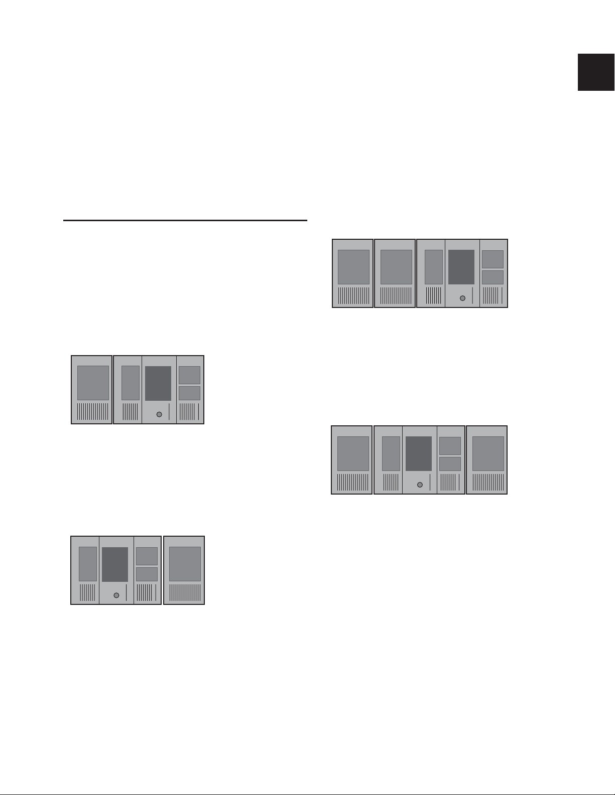
The D-Show Main Unit and Sidecar can be placed in any order, and the input channel strip order configured accordingly.
You can then bank input channels across the available input
channel strips.
Determining Control Surface Layout
Standard System Layout
On a standard D-Show system (one Main Unit and a single
Sidecar on the left), D-Show input channel strips 1–16 appear
by default on the Sidecar module, and channel strips 17–24
appear on the Main Unit.
(Bus ID 1) (Bus ID 2)
Strips 1–16 17–24
Main Unit Sidecar
Expanded System Layout
On expanded D-Show systems, by default, input channel
strips 1–16 appear on the leftmost Sidecar and progress to the
right.
Input channel strip numbering on an expanded system
You can place Sidecars on either side of the Main Unit, and
customize the order of input channel strips by changing the
Bus IDs of the units. See “Setting Control Surface Bus IDs” on
page 8.
Input channel strip numbering on a standard system
You can place the Sidecar on the other side of the Main Unit,
and customize the order of input channel strips by changing
the Bus IDs of the units. See “Setting Control Surface Bus IDs”
on page 8.
Main Unit Sidecar
Strips 1–8
Alternative input channel strip numbering on a standard system
Alternative input channel numbering on an expanded system
(Bus ID 2)(Bus ID 1)
9–24
Chapter 2: Configuring and Connecting D-Show 7
Page 18
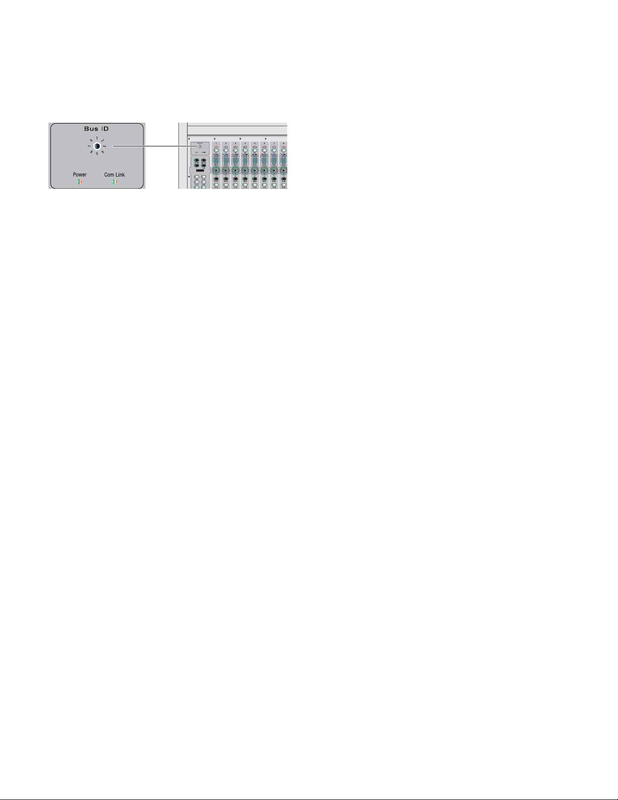
Setting Control Surface Bus IDs
All units have a Bus ID selector in the upper left of the control
surface top panel. Input channel strip numbering is determined by the Bus ID setting on each unit. Lower-numbered
bus IDs correspond to lower-numbered input channels.
Bus ID selector
To set the Bus ID on a unit:
■ With a small flat-head screwdriver, set the Bus ID as follows:
• Set the ID to 1 to have input channel numbering start on
that unit. Typically, this will be the leftmost unit in your
system.
• Set the ID to 2 on the unit you want to have the second
set of input faders. For example, on a standard D-Show
system (one Sidecar and one Main Unit) where the Sidecar is at the left of the Main Unit, the Main Unit should
be set to Bus ID 2.
• Set the ID of other units to match the layout of input
channels.
D-Show Guide8
Page 19
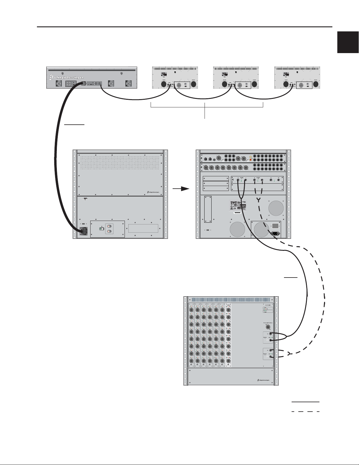
Connecting D-Show Components
Main Unit Sidecar Sidecar Sidecar
Light Light
Console Link
Console Link
Sidecar 4-6
Sidecar 1-3
IO
1
FOH Link
VGA
Footswitch
To Rack
USB
2
IO
IO IO
FOH Link Cable
FOH
USB
FOH Link
To
Control Surface
Power
FOH Rack (Front)
Console Link Cables
Com
TB Gain
MIDI
In
Out
IO
1 2In
AES 3 4
OutAES
IO x
System Drive
Reset
USB
In
2TR SPDIFOut2TR AES
12345678
L
Mon Left
2TR Out
R
Mic
P R
Mon Right
L
2TR In
R
OutIn
OutIn
AES 5 6
SNAKE
Out
12345678
AES SPDIF
In
OutIn
AES 7 8
910111213141516
910111213141516
Stage 1Expansion
Active
Active
Sig
Sig
Stage 2
.
.
DO NOT OBSTRUCT FANS
964530300294856
SERIAL NUMBER
Analog Out
+4 dBu
Analog In
+4 dBu
Analog Out
+4 dBu
Analog In
+4 dBu
Word Clock
Active
Sig
FOH Rack (Back)
Digital Snake Cables
Stage Rack (Front)
Figure 1. D-Show system component connections
SRI SRI SRI SRI SRI SRI SRO
ABCDEFGHJKLM
STAGE
Primary Snake
Redundant Snake
Chapter 2: Configuring and Connecting D-Show 9
Page 20
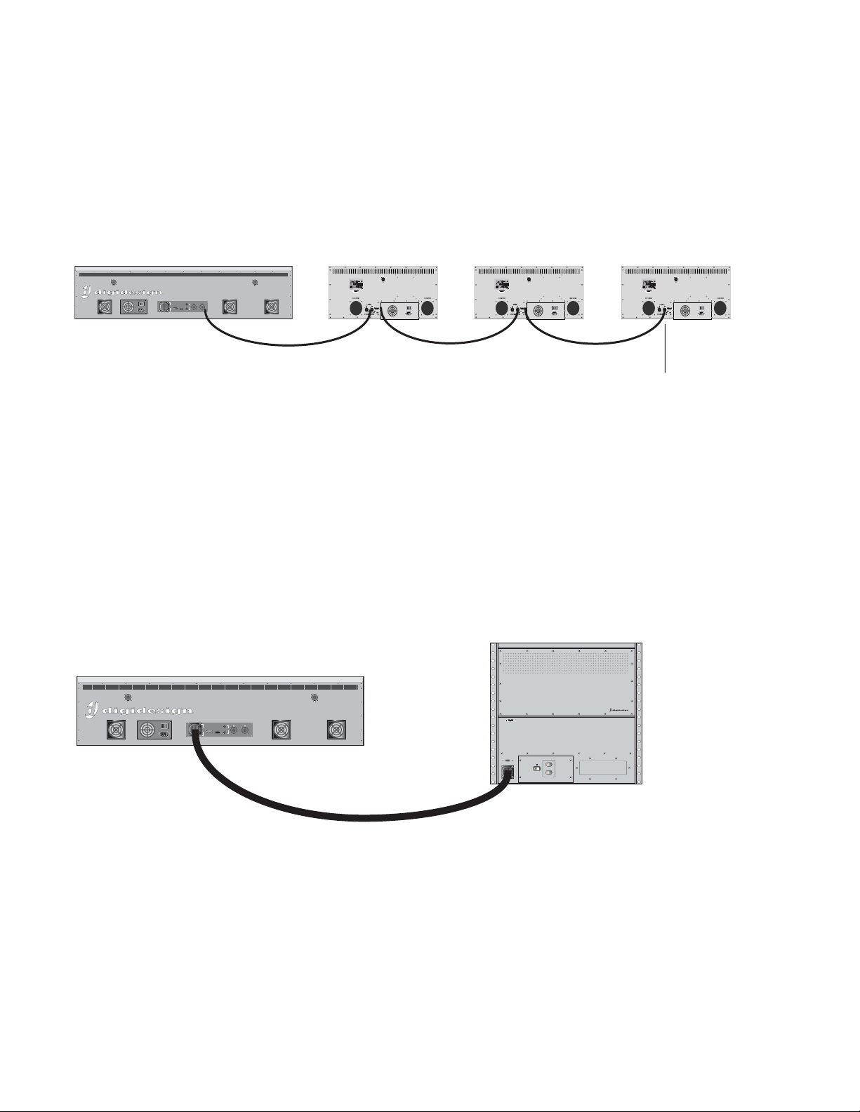
Connecting the D-Show Main Unit and Sidecars
The D-Show Main Unit and Sidecars are connected with Console Link cables (one 15-foot cable is provided with each Sidecar),
which are 110-ohm AES/EBU digital cables. The maximum length permissible for each Console Link cable is 25 feet (7.6 meters).
Up to three Sidecars can be connected to the “Sidecar 1–3” port on the Main Unit.
To connect the Main Unit and Sidecars:
1 Connect the Console Link In port on the back panel of the nearest Sidecar to the “Sidecar 1–3” port on the back panel of the
Main Unit.
2 On the successive Sidecars, connect the Console Link In port to the Console Link Out port on the previous Sidecar.
Light Light
Console Link
Console Link
Sidecar 4-6
Sidecar 1-3
IO
Figure 2. Console Link connections for Main Unit (left) and Sidecars (right)
3 On the last Sidecar only, terminate the Console Link connection with the Terminate switch.
1
FOH Link
VGA
Footswitch
To Rack
USB
2
IO
IO IO
Connection must be terminated
on last Sidecar in chain
Connecting the Main Unit to the FOH Rack
The D-Show Main Unit is connected to the FOH Rack with the provided FOH Link cable.
To connect the Main Unit and the FOH Rack:
■ Connect one end of the FOH Link cable to the FOH Link port on the back panel of the Main Unit. Connect the other end of
the FOH Link cable to the FOH Link port on the front panel FOH Rack. On each end, be sure to align the notch in the connector
housing with the slot in the plug, and to rotate the collar until the connector is fully latched.
Light Light
Console Link
Console Link
Sidecar 4-6
Sidecar 1-3
IO
1
FOH Link
VGA
Footswitch
To Rack
USB
2
Figure 3. FOH Link connection between Main Unit (left) and FOH Rack (right)
FOH
USB
FOH Link
Reset
Power
Control Surface
To
D-Show Guide10
Page 21
Connecting the Stage Rack to the FOH Rack
The Stage Rack is connected to the FOH Rack with the Digital Snake cable (purchased separately).
To connect the Stage Rack to the FOH Rack:
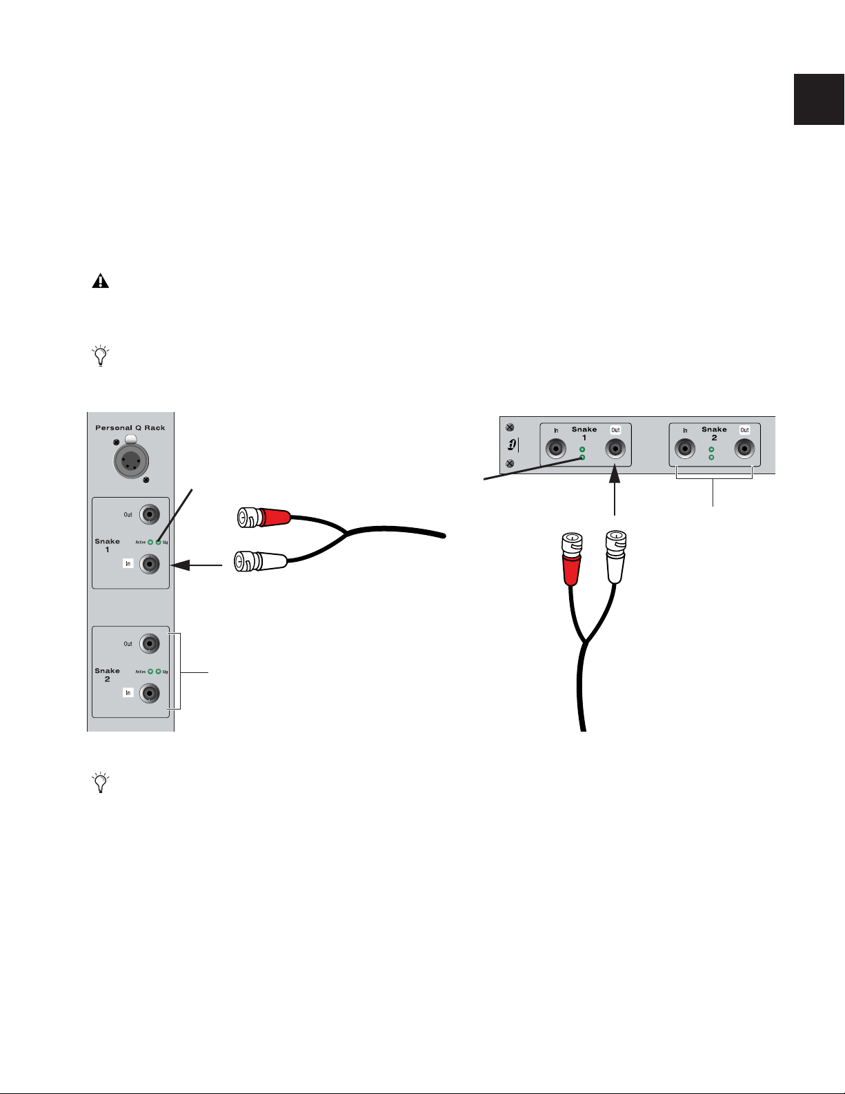
1 On the Stage Rack, connect the Digital Snake cable lead with the white connector sleeve to the Snake 1 In port (this port label
is outlined in white), and the Digital Snake cable lead with the red connector sleeve to the Snake 1 Out port.
2 On the FOH Rack, connect the Digital Snake cable lead with the white connector sleeve to the to the Snake 1 Out port (this
port label is outlined in white), and the Digital Snake cable lead with the red connector sleeve to the Snake 1 In port.
3 If you are using a second, redundant Digital Snake, connect it to the Snake 2 ports on each unit in the same manner, matching
the white connector sleeves to the ports whose labels are outlined in white.
The redundant Digital Snake must be the same length as the primary Digital Snake for each Stage Rack.
When the units are turned on, the Snake Signal LEDs (marked “Sig”) on the FOH Rack and the Stage Rack light solid to indicate
the Snake connection. If the Snake Signal LEDs flash, a Snake connection has not been established.
If there are problems with the Snake connection, double check that all the BNC connectors are fully secured. If the
problem persists, try reversing the red and white connectors on one end.
SNAKE
Signal LED
Signal LED
Connectors with white sleeves
attach to terminals with white labels
Redundant Snake
connects here
Figure 4. Detail of Digital Snake cable connection between Stage Rack (left) and FOH Rack (right)
If a second Stage Rack is used, an additional Snake Card must be installed in the FOH Rack. Follow the above instructions to connect the second Stage Rack to its corresponding Snake card.
Active
Sig
Active
Sig
Redundant Snake
connects here
Chapter 2: Configuring and Connecting D-Show 11
Page 22
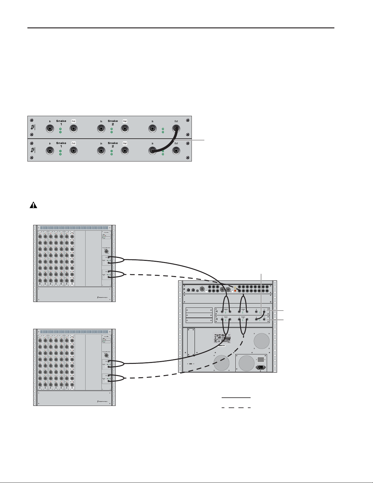
Connecting a Second Stage Rack
Before connecting a second stage rack to a D-Show system, a second Snake card (purchased separately) must first be installed in
the FOH Rack.
To connect a second Stage Rack:
1 Install a second Snake card in the FOH Rack. See the documentation that came with the Snake card.
2 Using a BNC cable (included with the additional Snake card), connect the Word Clock Out port on the first Snake card to the
Word Clock In port on the second Snake card.
Stage 1
SNAKE
SNAKE
Active
Sig
Active
Sig
Active
Sig
Active
Sig
Stage 2
Word Clock connection between Snake cards
3 Connect the second Stage Rack to the FOH Rack with a Digital Snake cable. See “Connecting the Stage Rack to the FOH Rack”
on page 11.
The redundant Digital Snake must be the same length as the primary Digital Snake for each Stage Rack.
Word Clock
Active
Sig
Word Clock
Active
Sig
BNC Cable
Snake 1
SRI SRI SRI SRI SRI SRI SRO
ABCDEFGHJKLM
STAGE
Stage Rack 1
SRI SRI SRI SRI SRI SRI SRO
ABCDEFGHJKLM
STAGE
Snake 2
Snake 1
Snake 2
Com
TB Gain
MIDI
In
Out
IO
System Drive
USB
Mon Left
Mic
P R
Mon Right
Primary Snake
In
L
2TR Out
R
L
2TR In
R
SNAKE
SNAKE
.
.
964530300294856
SERIAL NUMBER
FOH Rack
2TR SPDIFOut2TR AES
Out
AES SPDIF
In
Stage 1Expansion
Active
Sig
Active
Sig
Stage 2
DO NOT OBSTRUCT FANS
12345678
12345678
Redundant Snake
Stage Rack 2
Figure 5. Digital Snake cable and word clock connections for fully redundant system with 2 Stage Racks
Word Clock cable
Analog Out
+4 dBu
Analog In
+4 dBu
Word Clock
Active
Active
Sig
Sig
Word Clock
Active
Active
Sig
Sig
Snake Card 1
Snake Card 2
D-Show Guide12
Page 23
Power Connections
Each power supply in the Main Unit, the Sidecars, the FOH Rack, and the Stage Rack requires its own power connection. (If any
unit includes an optional redundant power supply, it will require two dedicated power connections.) Each power supply is auto
voltage-selecting (100V to 240V). A modular IEC power cable is provided for each power supply in the unit.
Audio and MIDI Connections
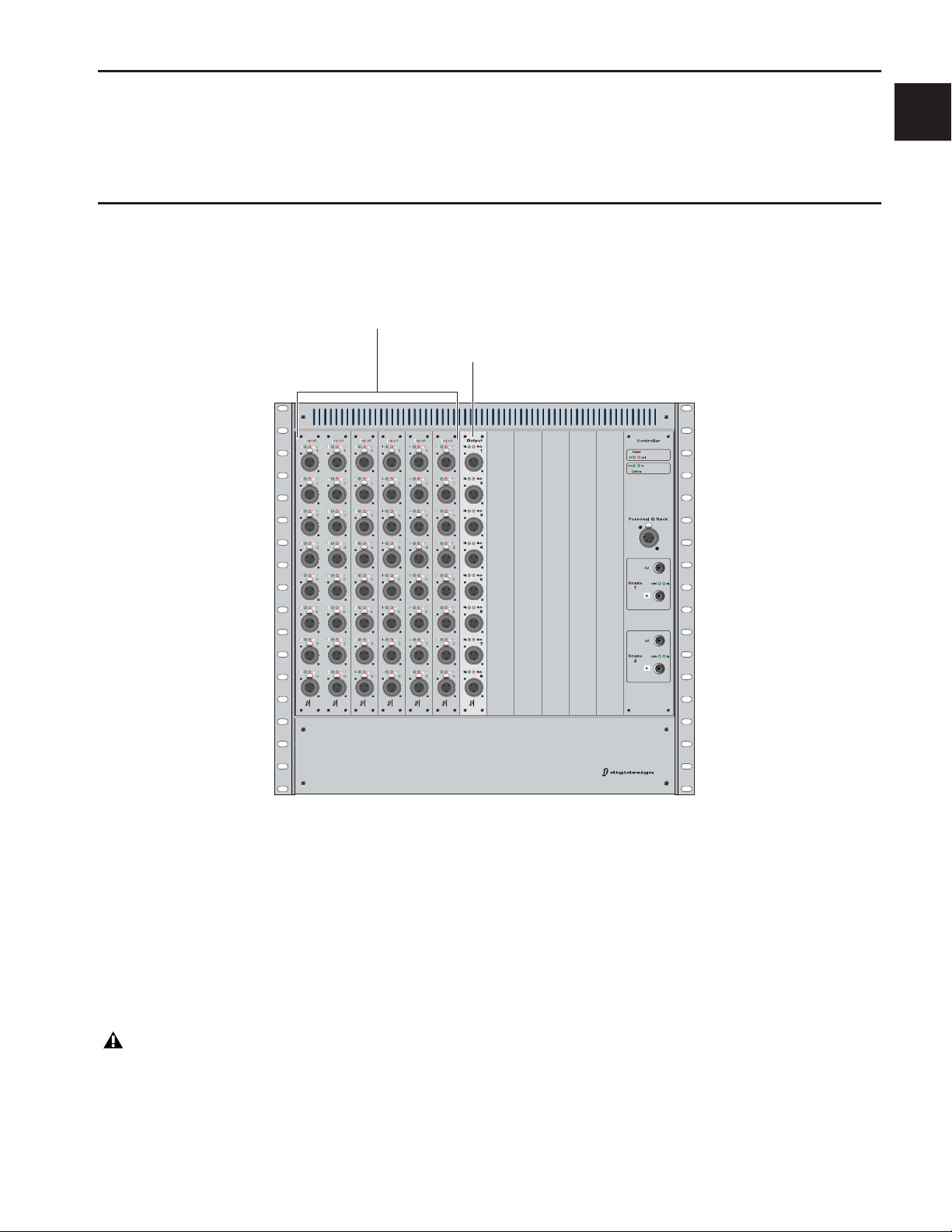
Stage Rack Connections
Stage Rack Input Cards
Stage Rack Output Card
SRI SRI SRI SRI SRI SRI SRO
ABCDEFGHJ KLM
STAGE
Figure 6. Audio connectors on Stage Rack
Audio Inputs
(Balanced Female XLR Connectors)
◆ Connect analog mic-level or line-level input sources to any
of the input connectors on any SRI Card.
Applying Phantom Power to Stage Rack Inputs
Each SRI Card input has available standard 48V phantom
power.
Before connecting or disconnecting a microphone on any
Stage Rack Input, make sure phantom power is turned off
for that input.
To apply phantom power to a Stage Rack input source:
1 Target a channel in the ACS section of the control surface.
2 Press the +48V switch in the ACS Input section.
The corresponding channel’s “+48V” LED on the Stage Rack
Input Card lights to indicate phantom power is on.
Audio Outputs
(Balanced Male XLR Connectors)
◆ Connect analog line-level output destinations (such as
power amplifiers, crossovers, or speakers) to any of the output
connectors on any SRO Card.
Chapter 2: Configuring and Connecting D-Show 13
Page 24
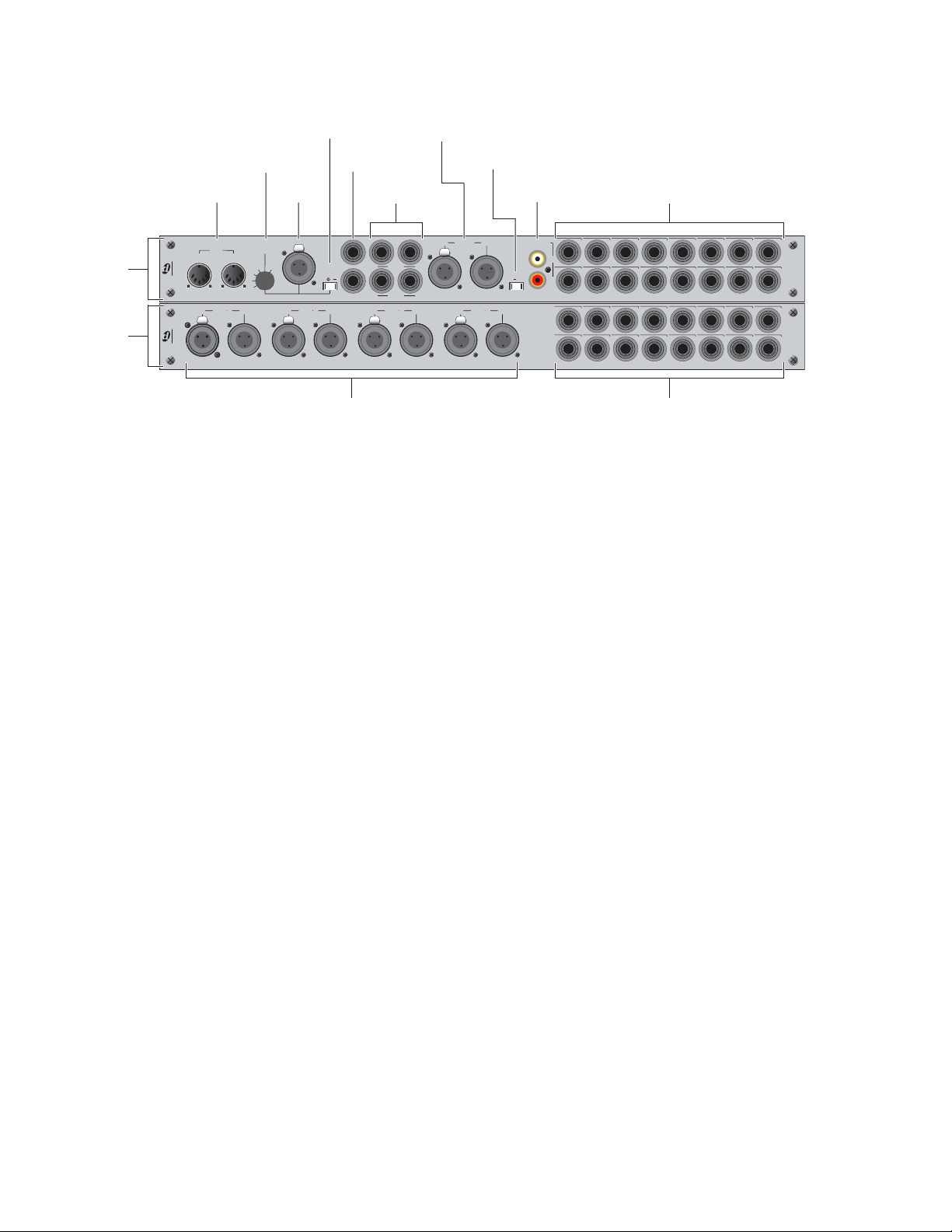
FOH Rack Connections
IO
section
IOx
section
(Optional)
Com Mic Phantom Power
Monitor
Com Mic Gain
Com Mic
Input
MIDI
In
IO
IO x
Gain
Out
1 2In
OutAES
Outputs
2-Track Analog I/O
Com
L
Mon Left
Mic
P R
Mon Right
AES 3 4
OutIn
L
2TR Out
2TR In
AES 5 6
2-Track
AES/EBU I/O
In
R
R
OutIn
2-Track Digital
Format selector
S/PDIF I/O
AES SPDIF
OutIn
AES 7 8
2-Track
2TR SPDIFOut2TR AES
Analog I/O 1–8MIDI I/O
12345678
Out
12345678
In
910111213141516
910111213141516
Digital I/O 1–8 Analog I/O 9–16
Figure 7. Audio connectors on FOH Rack, showing standard IO connectors (top) and optional IOx connectors (bottom)
Audio Inputs and Outputs
Analog Inputs and Outputs
(Balanced 1/4-inch TRS Connectors)
◆ Connect the analog inputs and outputs of external proces-
sors to any of these 8 analog output and input pairs. (16 inputs and output pairs are available if the IOx option is
installed.)
◆ Connect any analog output destination (such as a recording
device or broadcast feed) to any of the outputs in this section.
◆ Connect any analog sound sources (such as a CD player) to
any of the inputs in this section.
2-Track Inputs and Outputs
2-Track Analog Inputs and Outputs
(Balanced 1/4-inch TRS Connectors)
◆ Connect a 2-track analog playback source to the 2-Track
analog inputs.
◆ Connect a 2-track analog recording device to the 2-Track
analog outputs.
2-Track Digital Inputs and Outputs
(AES/EBU and S/PDIF Connectors)
◆ Switch the 2-Track digital I/O between AES/EBU and S/PDIF
by moving the 2-Track Digital Format selector switch to the
Digital Inputs and Outputs - IOx Option only
(AES/EBU Connectors)
◆ Connect the two-channel digital inputs and outputs of ex-
ternal processors to any of the 4 AES/EBU digital output and
input connectors in this section.
◆ These connectors support 24-bit, 48 kHz digital signals. In-
put signals with other sample rates are sample-rate converted
to 48 kHz.
corresponding position. Only one of these digital formats may
be active at a time.
◆ Connect a 2-channel digital playback source to the 2-Track
AES/EBU or S/PDIF input.
◆ Connect a 2-channel digital recording device to the 2-Track
AES/EBU or S/PDIF output.
◆ These connectors support 24-bit, 48 kHz digital signals. In-
put signals with other sample rates are sample-rate converted
to 48 kHz.
Analog Out
+4 dBu
Analog In
+4 dBu
Analog Out
+4 dBu
Analog In
+4 dBu
Monitor Outputs
(Balanced 1/4-inch TRS Connectors)
◆ Connect a monitor amplifier or powered monitors to the
Monitor Output connectors.
◆ The Monitor Outputs, and the Headphone Output on front
of the Main Unit, are fed by the Solo/Monitor bus
D-Show Guide14
Page 25
Com Mic Input
FOH Link
To Rack
Footswitch
Console Link
Sidecar 4-6
Console Link
Sidecar 1-3
VGA
USB
1
2
VGA Display connector
USB connector
FOH Link
To Rack
Footswitch
Console Link
Sidecar 4-6
Console Link
Sidecar 1-3
VGA
USB
1
2
USB connector
USB connector
Com Mic Connector
◆ Plug a dynamic or condenser microphone, or any compati-
ble intercom system microphone into this connector.
Applying Phantom Power to the Com Mic
The Com Mic input has available 15V phantom power.
Talkback Level
◆ The talkback gain for this connector is fixed at 20 dB.
◆ Adjust talkback send level by pressing the Talkback switch
in the Talkback/Osc section and turning the level knob.
Talkback Switch
◆ Activate talkback by pressing the On/Talk switch.
To apply phantom power to the Com Mic:
■ Move the Mic Power switch to the right.
Com Mic Gain
◆ Turn the Com Mic knob to adjust overall Com Mic gain.
MIDI Input and Output
◆ Connect a compatible MIDI device to the MIDI In and MIDI
Out ports. The D-Show Snapshot feature receives and sends
MIDI commands, and generates and responds to MIDI Time
Code.
Control Surface Connections
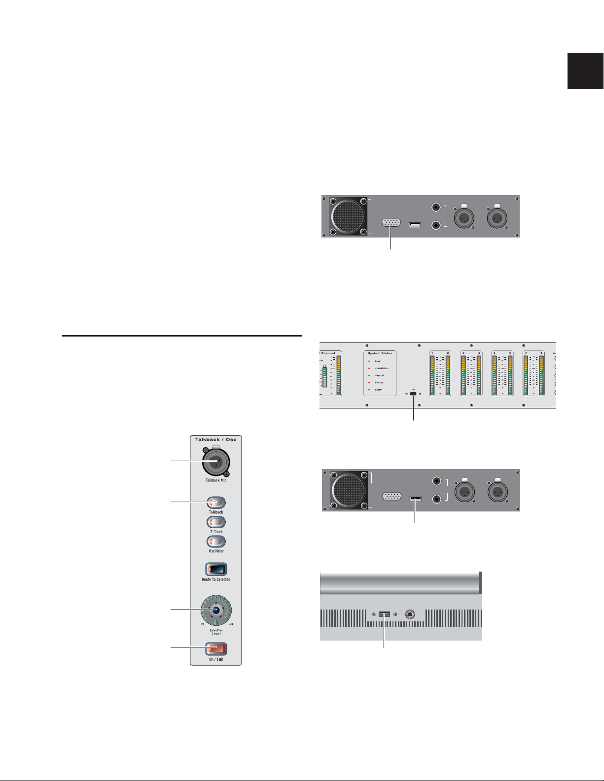
Talkback Mic
Talkback Mic Connector
◆ Plug a dynamic talkback microphone into this connector.
VGA Display
◆ Plug a compatible VGA display into this connector.
VGA display connector on back panel of the Main Unit
USB Keyboard
◆ Plug a compatible USB keyboard into any of the 3 available
USB connectors on the Main Unit.
USB connector on the meter bridge panel of the Main Unit
Talkback Mic connector
Talkback switch
Talkback level
On/Talk switch
Talkback microphone connector and controls on the Main Unit
USB connector on back panel of the Main Unit
USB connector on front panel of the Main Unit
Chapter 2: Configuring and Connecting D-Show 15
Page 26

Powering Up the System
Enabling a Second Stage Rack
D-Show faders move when power is turned on. Before powering up the system, make sure all fader paths on the Main
Unit and Sidecars are clear of obstructions.
Power up the system in the following sequence:
1 Main Unit and Sidecars
2 Stage Rack
3 Front of House Rack
4 Any connected computers for recording/playback options
5 Audio monitoring system
On units with redundant power supplies, each power supply
has a separate power switch.
Powering Down the System
Power down the system in the following sequence:
1 Audio monitoring system.
2 Any connected computers for recording/playback options.
3 Front of House Rack.
To enable and confirm communication with the second Stage
Rack:
1 Put D-Show in Config mode.
2 Go to the Options page and click the System Config tab.
3 Click Edit.
4 Select Enable Stage2, and click Apply. D-Show restarts.
Enabling the second Stage Rack
5 Go to Options > Devices to view D-Show hardware status.
The connection to the second Stage Rack should be displayed
in the FOH Rack graphic.
4 Stage Rack.
5 Main Unit and Sidecars.
Restarting the System
If at any time during setup or performance it becomes necessary to restart the system, you can restart the entire system or
reset individual hardware devices.
For more information on restarting D-Show and resetting
system hardware, see Chapter 27, “Troubleshooting.”
Setting the System Clock
When you first work with a D-Show system, make sure the system clock time, date and time zone are set appropriately. The
system clock setting can affect data synchronization with portable storage devices. See “Synchronizing Settings, Shows and
Presets” on page 157.
Changing the system clock while using a timed iLok license
(for a plug-in with a demo period, or for a plug-in rental)
may expire the plug-in authorization.
Detail of Devices page showing connection to second Stage Rack
The second Stage Rack must be enabled for the Devices tab
to display the correct number of SRI (Stage Rack Input) and
SRO (Stage Rack Output) cards in that unit.
D-Show Guide16
Page 27

Part II: System Description
Page 28

Page 29
Chapter 3: D-Show Control Surface Overview
D-Show Main Unit and Sidecar Top Panels
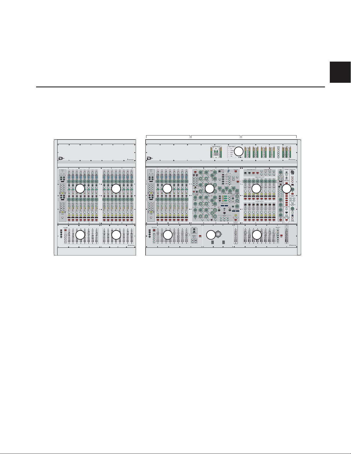
The following figure identifies the main sections of the D-Show control surface:
Main UnitSidecar
Input Section Assignable Channel Section Output SectionInput Channels
G
A
Make Stereo
BanksBanks
AA
BB
CC
DD
A A
BB
B
A Input Channels (banks of 8)
B Input Faders (banks of 8)
C Assignable Channel Section (ACS)
D Assignable Output Encoders
Figure 8. Control Surface main sections
The D-Show control surface consists of one Main Unit and
one or more Sidecars. The D-Show Main Unit provides eight
bankable input channel strips, the Assignable Channel Section (center section), eight Assignable Output Encoders, eight
Assignable Output Faders, and one Mains Fader and Master
Controls section.
Each D-Show Sidecar provides 16 additional bankable input
channel strips. Sidecars can be attached to the left of the Main
Unit (as shown above), attached to the right side, or kept
free-standing (unattached) on either side.
Input Section
The Input Section provides Input Channels and FX Returns,
with channel faders and two rows of assignable encoders.
CD
KICKKICK
KICK KICK
H
E
F
E Assignable Output Faders
F Master and Global Section
G Meter Bridge
H Trackball and View Mode Controls
Assignable Channel Section
The Assignable Channel Section provides expanded routing
and processing controls for the currently targeted channel.
Output Section
The Output Section includes two sets of output controls that
can be used to control two different sets of outputs at the same
time:
• The Assignable Output Encoders adjust the assigned output
or bus, or plug-in parameters (when in Insert mode), and are
also where you set up Matrix and PQ sends.
• The Assignable Output Faders adjust the assigned output,
bus, or VCA.
Chapter 3: D-Show Control Surface Overview 19
Page 30
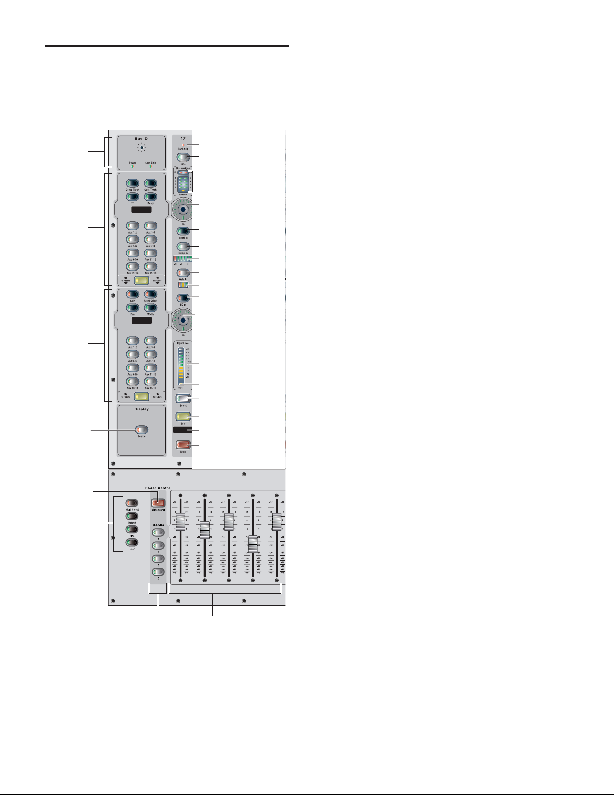
Input Channels and Faders
Inputs include Input Channels and FX Returns. Each input
strip provides level faders, solo, mute, and Select switches, two
rotary encoders (with selectable functions), Bus Assign LEDs
(routing indicators), as well as display LCDs and status LEDs.
Bus ID
controls
Encoder 1
assignment
controls
Bank Clip indicator
Safe switch
Bus assignment
indicators
Encoder 1
HW Insert In switch
Comp/Lim In switch
Comp/Lim meter
Exp/Gate In switch
Exp/Gate meter
EQ In switch
Encoder 2
Bank Clip Indicator
The Bank Clip Indicator lights to indicate a meter clip on an
Input Channel or FX Return at the corresponding position in
an alternate bank of channels. This indicator obeys the same
clipping threshold display rules as the Input Channel meters
(as set in the Options > Interaction page). It gives you an indication of extreme signal level in a currently hidden
(“off-bank”) layer.
Safe
Automation Safe or Solo Safe
The Safe switch controls either an input strip’s Automation
safe status or Solo safe status, depending on the current Input
Safe Switch setting. See “Input Safe Switches” on page 47.
Pressing a channel Safe switch toggles the current state of that
channel as follows:
Auto Safe Mode If the Safe LED is lit, the channel will not respond to Snapshot-driven changes. If the LED is off, that
channel will respond to any applicable changes driven by
Snapshots.
Encoder 2
assignment
controls
Source
switch
Make Stereo
switch
Global
Modifier
switches
Input meter
Stereo LED
Select switch
Solo switch
Name Display
Mute switch
FadersFader Banks
Solo Safe Mode If the Safe LED is flashing, the channel will
not respond to solo commands (it will not be muted if another channel’s solo button is pressed). If the LED is off, that
channel will be silenced when soloing another channel.
Input strip and fader controls
D-Show Guide20
Page 31

Bus Assignment Indicators
These green LEDs indicate Group bus assignments, and can
also show VCA or Mute Group membership for each channel.
By default, Group bus assignment is displayed.
LR
1–8
Stereo Pan
Group indicator LEDs on an Input Channel
C/M
Group Bus Assignment
◆ If the LR LED is lit, the input channel feeds the Left and
Right Main busses in either L–R or L–C–R panning mode (regardless of the Stereo Pan LED status).
◆ If the C/M LED is lit, the input channel feeds the C (center)
bus from the pan in L–C–R mode, or the M (mono) bus before
the pan. Stereo channels are summed to the mono bus.
◆ If a bus LED (1–8) is lit, the channel is feeding the corre-
sponding Group(s). If an LED is off, the channel is not feeding
that Group. The Bus Indicators can also show VCA and Mute
Group membership.
Use the Bus Assign switches in the ACS to route and assign
channels to busses (see “Assignable Channel Section
(ACS)” on page 24).
VCA Membership
◆ When the VCA Show Members switch is pressed, Group in-
dicator LEDs flash to indicate VCA assignment. A flashing LED
indicates that the channel is assigned to the corresponding
VCA (1–8).
Mute Groups
◆ When the Mute Groups Show Members switch is pressed,
the Group indicators flash to indicate Mute Group assignments. A flashing LED indicates that the channel is assigned
to the corresponding Mute Group (1–8).
Input Encoders and Assignment Controls
Input Channels contain two separate banks of rotary encoders
that can be assigned to control a variety of channel functions
such as input gain, HPF corner frequency, pan/balance/width,
and specific parameters of built-in Dynamics processes.
The Encoder Assignment switches, located to the left of each
row of encoders, determine the function of the encoders on
Input Channels. The LCD within each set of encoder controls
displays the current function.
Rotary and Switch Functionality
D-Show rotary encoders are dual-function controls that provide rotary and switch functions. In addition to adjusting parameters by turning the encoder, you can toggle parameters
(such as taking the high-pass filter in or out of circuit) by
pressing the encoder knob.
Encoder LEDs
Two types of LEDs surround each encoder:
◆ The LED ring around the encoder displays the relative posi-
tion of its currently assigned parameter.
◆ Below each encoder is an indicator LED, which indicates pa-
rameter status (in/out) and various conditions related to the
current encoder function.
Encoder 1 Assignment Switches and Functions
The Encoder 1 Assignment switches assign the following functions to Encoder 1 on each input channel strip:
Comp/Lim Thrsh Assigns the encoders to control the Threshold for the built-in Compressor/Limiter. Pressing the encoder
toggles the effect in and out of circuit.
Exp/Gate Thrsh Assigns the encoders to control the Threshold
for the built-in Expander/Gate. Pressing the encoder toggles
the effect in and out of circuit.
HPF Assigns the encoders to control the HPF corner frequency. Pressing the encoder takes the built-in HPF in and out
of circuit. If the LED is lit, the filter is in circuit.
Delay Assigns the encoders to control the amount of delay in
the channel. Pressing the encoder takes the Delay in and out
of circuit. If the LED is lit, the delay is in circuit.
AUX 1•2 TO AUX 15•16 Let you select one of two Aux sends
in odd/even pairs.
◆ With mono sends, the first press of the switch selects the
odd numbered send (1, 3, 5, or 7) and the second press selects
the even numbered send (2, 4, 6, or 8). The switch lights green
for the odd-numbered selection, or yellow for the even-numbered selection.
◆ With stereo-linked sends, the first press of the switch con-
trols level for the bus pair, and the second press controls pan
for the bus pair. The switch lights green for level control, or
yellow for pan control.
Pressing the Encoder 1 then toggles the send on or off. When
the send level is shown on the LED ring and the send is off, at
most a single LED in the ring lights. When the send is on, all
LEDs light in a clockwise sequence from the lower left to the
send level.
Chapter 3: D-Show Control Surface Overview 21
Page 32

When D-Show is in Variable Groups mode, the switches for
Aux 1–2 through Aux 7–8 can be used to select Variable Group
sends, and use the Encoder 1 to control the Variable Group
send on/off, level, and pan parameters.
Aux Pan With stereo-linked Auxes or Variable Groups, the
first press of this switch selects the level control for the Aux or
Variable Group bus pair (green LED) and the second press selects the pan/balance control for the pair (yellow LED). When
the Aux or Variable Group pair is following Main pan, the second press is not available. For more information, see “Aux Bus
Signal Flow Options” on page 76.
Width (Stereo Channels Only) Assigns the encoders to control
the ganged pan positions of Left channel and Right channel at
the same time, but in opposite directions. Turning clockwise
moves the pans towards full stereo, turning counter-clockwise
moves the pans toward reverse-stereo. Since width is only applicable to stereo strips, this control is disabled when the associated input strip is mono.
Gain Assigns the encoders to control input gain according to
the range available for this input. Pressing that holding the
encoder initiates Gain Guess, in which D-Show automatically
sets a nominal input gain level based on the incoming signal.
Pan mode is indicated by the single-dot LED ring light pattern. Stereo-linked busses use a yellow color backlight in their
name displays in the Outputs section to indicate stereo linking.
FLIP When enabled, the current encoder parameter is mapped
to the channel faders. It can still be controlled from the encoder row, so the channel fader mirrors the setting. When Flip
is engaged, all channel name display backlights turn yellow,
the same color as the flip switch.
It is not possible to flip controls for both sets of encoders at
once, and the last-pushed Flip switch overrides any previous Flip state.
Display The 6-character display shows information about the
currently selected function.
Table 4. Encoder 1 Displays
Switch Display
Comp Thr COMP
Gate Thr GATE
Delay DELAY
Aux AUX (number). Displays abbrevi-
Aux (stereo) APAN (number) Odd-numbered
Flip Retains current selection
HPF
ated name if Aux output is
changed from default name
Auxes display pan information
when Auxes are stereo-linked
Encoder 2 Assignment Switches and Functions
Right Offset (Stereo Channels Only) Assigns the encoders to
control the gain offset of the right channel relative to the left.
The offset ranges from –20 dB to +20 dB at the maximum but
this range can be restricted depending on the current Gain setting.
AUX 1•2 to AUX 15•16 Same as in Encoder 1 Assignment
panel (see “Encoder 1 Assignment Switches and Functions” on
page 21).
Flip Same as Encoder 1 Assignment panel (see “Encoder 1 Assignment Switches and Functions” on page 21).
It is not possible to flip controls for both sets of encoders at
once, and the last-pushed Flip switch overrides any previous Flip state.
Display The 6-character display shows information about the
currently selected function.
Table 5. Encoder 2 Display
Switch Display
Pan/Bal PANBAL
Width WIDTH
Gain INP GN
Gain R RGHTGN
Aux AUX (number). Displays abbrevi-
ated name if Aux output is
changed from default name
Flip Retains current selection
Aux (stereo) APAN (number) Odd-numbered
Auxes display pan information
when Auxes are stereo-linked
The Encoder 2 Assignment switches assign the following functions to Encoder 2 on each input channel strip:
Pan/Bal Assigns the encoders to control channel Pan if the
channel is mono, or stereo channel balance if a stereo. The indicator LED lights when the pan is at center.
D-Show Guide22
Insert In Switch
This switch toggles the hardware insert in and out of circuit (if
assigned). If the switch is lit, the process is in circuit. Insert
sends and returns are assigned in the Patchbay. On Inputs, the
insert send is always sending. This switch does not affect inserted plug-ins. Plug-ins can be bypassed individually in the
Assignable Channel Section.
Page 33

Comp In Switch
Select Switch
This switch toggles the built-in Compressor/Limiter in and
out of circuit. If the switch is lit, the process is in circuit.
Gate In Switch
This switch toggles the built-in Expander/Gate in and out of
circuit. If the switch is lit, the process is in circuit.
EQ In Switch
This switch toggles the built-in EQ in and out of circuit. If the
switch is lit, the process is in circuit.
Input Strip Meters
There are three meters within this section in the channel strip.
D-Show Input (and Output) meters display nominal level.
Input Meter
The 10-segment input meter displays the level of the incoming input signal. A segment lights when the level of the incoming signal reaches or exceeds the segment’s corresponding label.
The entire meter lights red if the signal is clipping at any of
the strip’s multiple clip points. Normally, segments up to and
including the segment labeled 0 dB display as green and the
segments above 0 dB display as yellow.
Because the lowest meter level is –30 dB, any input signal
that is less than this value will not register on the input
strip meter. The Selected Channel meter on the meter bridge
and the on-screen meters register activity below –30 dB.
Stereo LED Below the input meter is a Stereo LED. This LED
lights if the associated input strip is stereo. The LED flashes
on/off anytime the strip is stereo and the difference in instantaneous peak level between left and right sides is 12 dB or
more.
Comp/Lim Meter
The Compressor/Limiter meter has 6 LEDs to show the
amount of gain reduction being applied to the signal by the
built-in Compressor/Limiter. For more information, see
Chapter 16, “Dynamics.”
The Select switch on each channel is used to target the channel in the Assignable Channel Section, and to include the
channel in Multi-Select and Multi-Assign functions. A lit Select switch indicates the channel is selected. The name of the
currently selected channel is displayed in red in the Channel
Name display and in the ACS Selected Channel display. When
multiple channels are selected, the red Channel Name display
indicates which is channel is currently the ACS target.
Solo Switch
The Solo switch toggles the solo state of that channel. When
enabled, the Solo switch LED is lit. When the channel is in
Solo Safe mode, the Solo switch LED flashes. Channel Solo
latches on a momentary press, and automatically releases if
held for 2 seconds or more and released.
Source Switch
The Source switch changes the Channel Name display to
show the source input which is feeding each channel.
Name Display
This 6–character display shows the name of the channel, or
Source if the Source switch is pressed. The name display for
the currently selected channel is lit red. The channel name
display can show other types of information according to the
state of the Source switch or the current action.
Names This is the default display which shows the abbreviated channel names on all displays.
Values When a control is moved (or a fader is touched), the
Channel Name display changes to Values display mode,
where it shows each fader level or encoder function level as it
is adjusted. You can turn off Values display switching so that
the Name display does not show fader values. See “LCD Displays” on page 48.
Source When this switch is pressed, the Name displays show
the source input feeding each channel. Sources are abbreviated to indicate hardware input source and channel number.
For example, if “S1A1” appears in a Channel Name display
when Source is enabled, it indicates that the channel source is
Stage Rack 1, Card A, Input 1.
Expander/Gate Meter
The Expander/Gate meter has 3 LEDs to show the open/closed
state of the built-in Gate, or the amount of gain reduction applied by the Expander. For more information, see Chapter 16,
“Dynamics.”
Mute Switch
The Mute switch mutes the channel at the (pre-fader) mute
point. Channel pre-fader pickoff is post-mute.
Chapter 3: D-Show Control Surface Overview 23
Page 34

Faders
Each channel fader is a 100mm motorized, touch-sensitive
fader.
The Options > Interaction screen lets you enable touch-sensitive channel selection. When enabled, touching a channel
fader automatically selects that channel and makes it the ACS
target.
Assignable Channel Section (ACS)
The Assignable Channel Section provides dedicated routing,
EQ, Dynamics, and insert controls for the currently selected
channel.
Auxes
EQ
Channel Config
Console Config/Show mode
The faders on D-Show can be moved even when they do not
sense a touch. This allows use of the faders while wearing
gloves. It also lets you “throw” a fader and have it stay
where it lands, and not snap back to the point it was last
touched.
Fader Banking Controls
Bank A–D The Bank A–D switches bank the Input strips. Bank
width varies based on the number of Sidecars present. For example, on a system with one Sidecar, Bank A is channels 1–24,
Bank B is channels 25–48, and so on. On systems with two
Sidecars, Bank A is channels 1–40, Bank B is channels 41–80,
and so on.
FX Returns The FX Return switches bank FX Return channels
to the Input faders of the Main Unit.
Graphic EQ The Graphic EQ switches bank bands of graphic
EQ to the faders. Graphic EQs can be used on D-Show outputs
only. For more information, see Chapter 17, “EQ.”
Global Modifier Switches
To the left of the Bank A–D switches are the global modifier
switches. See “Global Modifier Switches” on page 30.
Multi-Select Lets you select multiple input channels.
Bus Assign
Input controls
Options, Snapshots and View modes
ACS main sections and controls
KICKKICK
KICK KICK
Insert
Processing
Dynamics
Direct Out
Display
Solo
Channel
Scroll
Mute
Input Controls
This section provides direct access to channel gain, HPF, delay, phantom power, and polarity (phase) for the currently selected channel.
Bus Assign
The Bus Assign switches are the primary routing controls for
the currently selected channel, letting you bus it directly to
the Main (L–R) bus or to any other mono or stereo group.
Default Lets you reset a parameter, section, or channel to default values.
Fine Lets you adjust rotary encoders with greater resolution
for finer control.
User This switch is currently not implemented.
Make Stereo Switch
The Make Stereo switch lets you combine two mono channels
into one stereo channel, or split a stereo channel into two
mono channels. See “Combining Input Channels (Make Stereo)” on page 52..
D-Show Guide24
When D-Show is in Variable Groups mode, the Stereo Pan
Switch in this section is used to display Variable Group parameters on the ACS Aux Sends controls.
Aux Sends
The Aux Sends section provides in/out and level control to
route the currently selected channel to any available mono or
stereo-linked Aux bus.
When D-Show is in Variable Groups mode, the controls for
Aux 1–2 through Aux 7–8 can be used to route the currently
selected channels to any available mono or stereo-linked Variable Group bus.
Page 35

EQ
Output
Encoders
Output Encoder function switches
LEDs
Channel Scroll
The EQ section provides dedicated controls for all built-in and
compatible plug-in EQ parameters including band in/out, frequency, Q, and mode.
See Chapter 17, “EQ.”
Channel Config
The Channel Config controls include the Input Direct and
Dyn Pre EQ switches.
Input Direct Bypasses the built-in Dynamics and EQ processing, and all inserts on the currently targeted Input Channel or
FX Return. The switch flashes to indicate Input Direct is active.
Dyn Pre EQ Enable Dyn Pre EQ to route audio on the currently
targeted Input Channel to built-in Dynamics first, then to
built-in EQ. The switch lights to indicate Dynamics precedes
EQ in the signal path.
Config/Show Mode
This switch toggles D-Show between these two operational
modes.
The Channel Scroll switches let you target other channels to
bring them to the ACS (as an alternative to pressing channel
Select switches). Press “+” to select the next channel. Press “–”
to select the previous channel. Holding down either Channel
Scroll switch scrolls continuously until the switch is released.
Options and Snapshots
The Options and Snapshots section, directly above the View
Mode switches, provides access to the snapshots list.
Selected Channel Fader
The Selected Channel Fader is a 100mm, touch-sensitive fader
that duplicates the fader for the selected channel.
Assignable Output Encoders
This section includes the eight Assignable Output Encoders
and their corresponding function switches.
See Chapter 6, “Options.”
Insert Processing
The Insert Processing section provides controls to bypass and
adjust plug-ins on the currently selected channel, as well as to
bypass hardware inserts.
Dynamics
The Dynamics section provides dedicated controls for built-in
and plug-in dynamics processors, including a comprehensive
set of Compressor/Limiter and Expander/Gate controls.
See Chapter 16, “Dynamics.”
Direct Output
The Direct Output section provides level and in/out control
for the channel direct output.
Solo and Mute
These switches provide channel Solo and Mute for the currently selected channel.
Assignable Output Encoder section
The switches to the right of the output encoders determine
the function of the Output section Encoder row and its controls. When a function is selected, the Output Encoder section
provides level control (using the encoders), solo, mute, and select switches for that output type.
Output Encoder Function Switches
Aux 1–8 Assigns the Output Encoder section to Auxes 1–8.
Aux 9–16 Assigns the Output Encoders section to Auxes 9–16.
Groups Assigns the Output Encoders section to Groups.
When D-Show is in Variable Groups mode, this switch assigns
the Output Encoders section to control Variable Groups.
Group Pan Assigns the Output Encoders to (stereo) Group pan.
Display Shows the currently assigned function of the Output
Encoder section.
Matrix and PQ Sends
The switches in the Matrix and PQ Sends section assign the
Output Encoders to the following functions:
Chapter 3: D-Show Control Surface Overview 25
Page 36

Matrix Sends Assigns the Output Encoders to control matrix
input source levels and enables.
PQ Sends Assigns the Output Encoders to control PQ input
source levels and enables.
PQ Pan Assigns the Output Encoders to control PQ input
source panning.
Matrix/PQ 1–8 Assign the Output Encoders to show Matrix or
PQ send levels and enable status, or Pan for selected Matrix or
PQ send.
Left, Center, Right, and User Send Control the level of the
Left, Center, Right, or User bus to the currently selected Matrix or PQ bus. Rotating the encoder adjusts the level; pushing
the encoder toggles the send in/out.
INSERT LED
Insert LED color indications
Color Meaning
Green Output has at least one of the fol-
lowing currently in-circuit: a hardware insert, and/or at least one
non-EQ and non-Dynamics plug-in
Yellow Output has at least one of the fol-
lowing but none are in-circuit: a
hardware insert, or a non-EQ and
non-Dynamics plug-in
Off Output has no hardware insert or
plug-in
Solo, Mute, and Select Provide solo, mute, and select for
Auxes or Groups assigned to the Output Encoders.
Output Encoder and Output Fader Status LEDs
These multi-color LEDs indicate EQ, dynamics, plug-in, and
insert status for the corresponding Assignable Output Encoders and Assignable Output Faders.
EQ LED
EQ LED color indications
Color Meaning
Green Output has a Graphic EQ and/or
one or more EQ plug-ins assigned
and in-circuit
Yellow Output has a Graphic EQ and/or
one or more EQ plug-ins, but none
are in-circuit
Off No Graphic EQ or EQ plug-ins are
assigned on the current output
DYN LED
Dyn LED color indications
Color Meaning
Assignable Output Faders
The Assignable Output Faders control the currently selected
Output type (Auxes, Groups, Matrix, PQ, or VCAs), chosen using the Output Faders switches.
Output Faders switches
Output faders
Aux 1–8 Assigns the Output Faders to control Aux 1–8 levels.
Aux 9–16 Assigns the Output Faders to control Aux 9–16 lev-
els.
Personal Q’s Assigns the Output Faders to control PQ mixer
output levels.
Matrixes Assigns the Output Faders to control Matrix mixer
output levels.
Green Output has a Dynamics plug-in
assigned and in-circuit
Yellow Output has one or more Dynamics
plug-ins, but none are in-circuit
Off No Dynamics plug-ins are
assigned on the current output
D-Show Guide26
Groups Assigns the Output Faders to control Group levels.
When D-Show is in Variable Groups mode, this switch assigns
the Output Faders to control Variable Groups.
VCAs Assigns the Output Faders to control VCAs.
Page 37

Master and Global Controls
The Master and Global section is located at the far right of the
Main Unit. It includes the Monitoring, Mute Groups, Mains,
Talkback/Com, Function, and Solo/PFL sections and controls.
Mute Groups
Mute Groups let you quickly mute multiple channels at the
same time. You can create and recall up to eight Mute Groups
comprising one or more channels.
See Chapter 15, “Muting and Mute Groups.”
Monitoring
Mute
Groups
Mains
Mains
Fader
Talkback/Osc
Function
Cancel
Solo/PFL
Mains Controls and Fader
This fader and its function switches let you control the Main
bus levels (L–R+M, or L–C–R).
The function switches directly above the Mains Fader let you
select which Main output bus the Main Fader controls. This
lets you assign the Mains Fader to all the Main busses (L–R+M,
or L–C–R) simultaneously, or to individual Main busses to
trim and balance Main bus output levels.
On-screen, three discrete faders are provided for L, R, and
C/M. By default, the on-screen L and R faders are linked for
stereo level adjustment; drag the C/M fader to adjust its
level. On the control surface, all three Mains channels are
enabled at the Mains Fader (L, R, and C/M).
Talkback/Osc
The controls in this section provide comprehensive and flexible communication control, including a top-mounted Talkback input (XLR), Assign switches, and level control.
Function Switches
This section provides four Main Function switches (F1, F2, F3,
and F4) and the Cancel switch.
Master and Global controls
Monitoring
This section provides level and delay controls for near-field
monitors and headphones. Separate level controls are provided for the monitor and headphone outputs. The Delay
switch lets you set an amount of delay to be applied to both,
to time-align their output at the front of house position.
F1 Serves as a clutch to be able to trim one side of a stereo
linked Aux without affecting the other side.
F2 When D-Show is in Variable Groups mode, the F2 switch is
used to toggle display of Variable Group controls in the Input
Encoder rows and the ACS.
The remaining Function switches are reserved for future use.
Cancel Cancels the current operation, such as Multi-Select or
Multi-Assign modes, or channel solo.
Solo/PFL
This section provides control over the primary Solo features,
including Solo Level and mode selection. Numerous options
are provided to customize D-Show Solo operation in the Options screen.
See Chapter 14, “Solo and Monitor Busses.”
Chapter 3: D-Show Control Surface Overview 27
Page 38

Meter Bridge
The Meter bridge displays level for the currently chosen output type, as well as high-resolution Selected Channel meters
for the currently selected channel.
Trackball and View Mode Controls
Trackball
The Trackball and its two switches are used to navigate
on-screen.
View Modes
Selected
Channel meters
System Status
Meters, displays, and controls in the Meter bridge
Output meters
Main Outputs
meters
Output Meter
Assign switches
Meters
The Meter bridge Output meters can be assigned to show Aux,
Group, Mains, or other output levels. By default, output metering follows Output Fader assignment. You can also designate which output type to display in the Output meters.
See Chapter 13, “Metering.”
System Status Panel
The System Status Panel provides LEDs that indicate the status
of system communication. Use these LEDs to confirm connections and communication between components, and for troubleshooting.
When all components are communicating properly, the Status LEDs light green. If any Status LEDs are flashing, or red, it
indicates possible problems with that component of the system.
The View Mode switches (Inputs, Outputs, Filing, Snapshots,
Patchbay, Plug-ins) display the corresponding pages
on-screen. Pressing a View Mode switch repeatedly cycles
through the individual tabs of that page. For example, pressing the Patchbay switch once displays the Patchbay screen.
Pressing Patchbay again cycles through various tabs within
the Patchbay page.
See Chapter 27, “Troubleshooting.”
D-Show Guide28
Page 39

Chapter 4: Basic Commands and Modes
Tool Tip
Banner display Mode display
Control Overview
Most D-Show features and controls that are used during a performance are available from both the control surface and
on-screen. Changes made on one are immediately reflected in
the other, letting you use almost any combination of control
surface and screen controls to mix.
The software screen is not required in order to mix a performance, as all mixing controls are provided on the control surface. However, the screen is essential when setting up and
configuring the system before a performance.
Software-Only Controls and Displays
Many configuration settings and options are only available
on-screen. These controls include hardware configuration settings, bus options, plug-in installation, and system diagnostics. For more information, see “System Configuration” on
page 41.
Software Screen Banner Display
The software screen provides a banner display in the lower left
corner. This display is provided to maintain line-of-sight mixing by showing the currently adjusted parameter (such as
fader level or compression threshold) as you make changes to
the parameter. The banner display also provides Tool Tip text
and status messages.
Tool Tips
With the Trackball, place the cursor over a screen item to display a brief explanation of that item in the banner display.
Status bar showing Tool Tip
Status Messages
The banner display alerts you to certain operating conditions
such as Multi-Select and Multi-Assign modes.
Banner display showing current state of the system
Control Surface and Software Screen Linking
The software screen is linked to control surface actions by default. For example, touching an input channel fader on the
Main Unit or a Sidecar changes the screen to Inputs page, and
touching an output bus fader changes the screen to the Outputs page.
You can customize how D-Show targets channels on the Assignable Channel Section to best match your working style.
For more information, see “Interaction” on page 47.
Chapter 4: Basic Commands and Modes 29
Page 40

Config Mode and Show Mode
Global Modifier Switches
D-Show has two main operating modes, Config Mode and
Show Mode. Use Config mode to set up your system and options; use Show mode to mix your performance.
Config Mode
Config mode provides access to the configuration settings
that are typically performed as part of system setup (before
mixing). For example, you must be in Config mode to do any
of the following:
• Choose a Main mix format (L–R+M, or L–C–R)
• Designate the number and mono/stereo format of available auxes and groups, combine two mono channels into
one stereo input channel, or split a stereo input channel
into two mono channels.
• Install plug-ins
• Assign plug-ins in the D-Show software racks
• Route side-chain inputs to plug-ins
• Initialize (or reset) hardware devices and options
• Customize soloing, metering, and Talkback/Com routing
• Customize control surface and software interaction
• Move channels to different fader strips
• Perform system tests and diagnostics
Some Config mode operations interrupt audio throughput.
Show Mode
Show mode is the main operating mode for D-Show. All mixing and routing features are available, based on your settings
for Config mode options.
D-Show provides a set of global modifier switches, located at
the lower left corner of the Sidecar and Main Unit: Multi-Select, Default, Fine, and User.
Multi-Select
Default
Fine
User
Global modifiers
These switches provide frequently used shortcuts that can be
applied to control surface actions and software screen interactions.
Multi-Select Switch
The Multi-Select switch lets you select multiple Input Channels and then apply an action to all selected channels.
Multi-Select is useful for batch routing and assignment of input channels.
Most channel functions support Multi-Select (or Multi-Assign) as noted throughout this guide. For details on how to select one or more channels, see “Selecting and Targeting Channels” on page 36.
Default Switch
Toggling D-Show Between Config Mode and
Show Mode
To toggle D-Show between Config mode and Show mode, do one
of the following:
■ Press the Console Config switch (located at the upper right
of the Assignable Channel Section).
– or –
■ Double-click the Mode display in the Status Bar, located in
lower-right hand corner of the screen.
D-Show Guide30
The Default switch provides a quick way to reset a control to
its default setting (or “zero” the setting). It is equivalent to,
and interchangeable with, the Alt key on the keyboard.
Examples of Using Default
To reset a fader to 0 dB:
1 Press and hold the Default switch.
2 Press the Select switch on the channel you want to reset.
To reset all EQ parameters on a channel:
1 Press and hold the Default switch.
2 Press the EQ In switch (use the channel strip EQ In, or the
ACS EQ In switch if the channel is currently selected in the
ACS).
To reset a single EQ parameter :
■ Hold the Default switch and press the encoder or switch for
that parameter.
Page 41

To reset Threshold on-screen:
Click page name to display
1 Select an input or output channel on-screen.
Software Screen Pages and Tabs
2 Do one of the following:
•Right-click the Threshold encoder on-screen and choose
Reset.
– or –
•Hold the Default switch on the control surface and click
the Threshold encoder on-screen.
To reset a parameter using only the keyboard and trackball,
press Alt+the on-screen control.
Fine Switch
The Fine switch lets you adjust controls (except for faders), on
the control surface or on-screen, with maximum resolution.
For example, if by default a controls adjusts a parameter in
units of 1 dB, the Fine switch lets you adjust in units of 0.1 dB.
To adjust a control with fine resolution:
■ Press and hold the Fine switch while moving a control. The
display associated with the adjusted control will show the values changes at the corresponding resolution.
Momentary and Latching Modes
Viewing Pages
To view a page, do any of the following:
■ Press a View mode switch (located at the bottom right of the
ACS).
– or –
■ Click the page name at the top of the screen.
When additional tabs are available for a page, go to those tabs
by clicking their names.
The Fine switch supports momentary and latching operation.
Momentary In momentary mode, the Fine switch stays in effect for as long as you hold down that modifier switch.
Latching In latching mode, the Fine switch stays in effect until
you explicitly clear its active state.
To use the Fine switch in Momentary mode:
1 Press and hold the Fine switch.
2 Adjust a channel, parameter, or processor.
3 Release the Fine switch.
To use the Fine switch in latching mode:
1 Double-press the Fine switch. The switch LED lights.
2 Select or adjust one or more channels, parameters, or pro-
cessors.
3 Press the Fine switch again to exit latching mode.
User
The User switch is reserved for future use.
Viewing pages
Chapter 4: Basic Commands and Modes 31
Page 42

Overview of Software Pages
Filing
The software screen provides the following pages and tabs.
Inputs
Select, name, configure, and adjust parameters for input channels and FX Returns.
Inputs page
See Chapter 7, “Inputs and Input Routing.”
Load, save, and transfer shows and presets.
Filing (Load tab)
See Chapter 20, “Shows and File Management.”
Snapshots
Store and recall snapshots.
Outputs
Select, name, configure, and adjust parameters for outputs.
Outputs page
See Chapter 8, “Outputs and Output Routing.”
Snapshots page
See Chapter 21, “Snapshots.”
D-Show Guide32
Page 43

Patchbay
Options
Route and name physical inputs and outputs to control surface channels.
Patchbay (Inputs tab)
See Chapter 12, “Patchbay.”
Plug-Ins
Configure and arrange plug-in racks by assigning plug-ins;
patch/route and manage plug-ins.
Configure control surface, Main busses (L–R+M, L–C–R), customize/optimize targeting, metering, modes, devices, install
plug-ins, and set other system options.
Options page (System Config tab)
See Chapter 6, “Options.”
Plug-In page
See Chapter 19, “Plug-Ins.”
Chapter 4: Basic Commands and Modes 33
Page 44

D-Show Guide34
Page 45

Chapter 5: Navigating and Selecting Channels
To bank Input Channels while keeping FX Return channels on the
Banking Input Channels and FX Returns
Many D-Show configurations utilize more physical inputs
than input faders. For example, a standard D-Show system
provides up to 48 discrete hardware inputs and 24 input faders. To navigate to channels beyond the number of physical
faders, D-Show provides channel banking controls.
The Bank switches move the display of channels on the control surface through other available banks.
• Input Channels are banked using the Bank A, B, C, and D
switches, located to the left of the input faders on both
the Main Unit and Sidecars.
• FX Returns are banked using the FX Returns switches, located to the right of the eight input faders on the Main
Unit.
Press to bank
FX Returns
Main Unit input faders:
■ Press any of the Bank switches (A, B, C, D) on any Sidecar.
To return the Main Unit input faders to Input Channel banking, do
one of the following:
■ Press a lit FX Returns switch (1–8 or 9–16).
– or –
■ Press any of the Bank switches (A, B, C, D) on the Main Unit.
Banking Graphic EQ Frequency Bands
When a built-in Graphic EQ is inserted on the currently targeted output or bus, its frequency bands can be banked to the
eight Input faders on the Main Unit.
See Chapter 17, “EQ.”
Press to bank input channels on
Main and Sidecars
Bank switches for inputs
To bank Input Channels to the input faders:
■ Press the appropriate Bank switch (A, B, C, or D).
To bank FX Returns to the Main Unit:
■ Press a Fader Control switch (FX Returns 1–8, or FX Returns
9–16).
When you press the Bank switches (A, B, C, D) on any Sidecar
(no the Main Unit), FX Returns will remain banked to the
Main Unit input faders. This lets you have input and FX Returns available simultaneously.
Flip mode can be used to put Aux send level at Sidecar Input
faders, leaving Main Unit input faders to control their FX
Return level.
Banking the Assignable Output Encoders and Assignable Output Faders
Outputs can be targeted and banked to the Assignable Output
Faders (AOFs) or to the Assignable Output Encoders (AOEs).
These two sections can target independently, letting you view
and control two banks of eight outputs simultaneously, as
available in each control section, as follows:
Assignable Output Encoders These can target Auxes 1–8,
Auxes 9–16, Groups (or Variable Groups), Matrix mixer inputs, or PQ mixer inputs.
Assignable Output Faders These can target Auxes 1–8, Auxes
9–16, Groups (or Variable Groups), Matrix mixer outputs, PQ
mixer outputs, or VCAs.
Chapter 5: Navigating and Selecting Channels 35
Page 46

To assign Aux, Group (or Variable Group), Matrix, or PQ controls
to the Assignable Output Encoders:
■ Press Encoder Assign switch, located to the right of the Out-
put Encoder row.
Selecting and Targeting Channels
Each D-Show channel strip has a channel Select switch. The
Select switch targets that channel for routing or processing assignment. Channels can also be selected by clicking their
fader strips on-screen.
When a single channel is selected, it becomes the targeted
channel. The fader level and all other parameters of targeted
channel can be adjusted from the ACS or from the selected
channel controls on-screen.
Press to assign encoders
Assignable Output Encoder controls
To assign Aux, Group (or Variable Group), Matrix, PQ, or VCA
controls to the Assignable Output Faders:
■ Press the corresponding switch in the Output Faders sec-
tion. Choices are Aux 1–8, Aux 9–16, Personal Q, Matrixes,
Groups, and VCAs.
To select a channel, do one of the following:
■ Press the Select switch on the control surface channel strip.
– or –
■ Click anywhere in the on-screen channel fader strip, except
on the fader, mute, solo or safe buttons.
Click to select channel
Clicking on-screen to select a channel
Multi-Select
Multi-Select lets you select multiple channels in order to apply
an action to them in one step.
Press to assign faders
Bank switches for Output channels
D-Show Guide36
Multi-Select only applies to channels. To select multiple
snapshots or other named items, use the Shift key on the
keyboard.
To select multiple channels from the control surface:
1 Press and hold the Multi-Select switch (located above the in-
put Bank switches). The switch flashes to indicate Multi–Select
mode.
2 Press Select on each channel you want to include in the se-
lection.
3 Release the Multi-Select switch.
4 Perform a routing assignment or other function (for exam-
ple, press a Bus Assign switch on one of the included channels). The operation is applied to all selected channels.
You can use the Shift key on the keyboard in place of the
Multi-Select switch to select multiple channels.
Page 47

To exit Multi-Select mode, do one of the following:
■ Press Cancel.
– or –
■ Press the Select switch on a channel that is currently not se-
lected.
To select multiple channels on-screen:
■ Press and hold the Multi-Select switch (or hold Shift on the
keyboard) and click the fader strips on-screen.
To select an 8-channel bank on-screen:
■ Click the bank name below the on-screen fader strips.
Click to select
banks of 8
Clicking a bank display to select multiple channels on-screen
To select all input channels or all output channels on-screen:
■ Double-click any bank name below the on-screen fader
strips in the Input or Outputs screen.
To remove a channel from a selection:
■ Control-click a highlighted channel.
See “Screen Controls and Shortcuts” on page 38 for additional on-screen features.
Multi-Assign
There are two types of Multi-Assign switches on D-Show, as
follows:
Using Multi-Assign to Route Channels to Main or Group Busses
To route multiple channels to any number of Main or Group
busses:
1 Target the first channel you want to route to the Main or
Group busses by pressing its Select switch.
2 Press the Multi-Assign switch in the ACS Bus Assigns sec-
tion.
3 Press the Select switches on the other channels you want to
route to a Main or Group bus.
4 In the ACS Bus Assigns section, press any of the Main or
Group bus switches so that they are lit.
5 Press the flashing Multi-Assign switch to confirm the assign-
ment, or press the Cancel switch to cancel the assignment.
Using Multi-Assign to Route Channels to Output Busses
To assign multiple channels to an Aux, Group (or Variable Group),
or VCA:
1 Press one of the following switches in the Output Fader as-
signment section:
• Aux 1–8
• Aux 9–16
• Groups
• VCAs
2 Press the Multi-Assign switch above the Assignable Output
Fader where you want to make the assignment. The flashing
Multi-Assign switch and the banner display at the lower left of
the screen indicate that Multi-Assign mode is enabled.
3 Press the Select switches on the channels you want to assign
to the Aux, Group (or Variable Group) or VCA.
ACS Bus Assigns The Multi-Assign switch in the ACS Bus Assigns section is used to route channels to the Main and Group
busses.
Assignable Output Faders The Multi-Assign switch on each Assignable Output Fader is used to route channels to Output
busses or VCAs.
4 Press the flashing Multi-Assign switch to confirm the assign-
ment, or press the Cancel switch to cancel the assignment.
See Chapter 8, “Outputs and Output Routing.”
Chapter 5: Navigating and Selecting Channels 37
Page 48

Type Text Search
Type Text search lets you use the keyboard for fast navigation
to a channel or snapshot. You can enter the first characters of
a channel name or the absolute channel number to target that
channel on the ACS. (See also “Selecting and Targeting Channels” on page 36.)
Screen Controls and Shortcuts
Adjusting On-Screen Faders
You can move on-screen faders independently or in ganged
fashion.
To search for and select a channel by name:
1 Go to the Inputs, Outputs, or Patchbay page.
2 Type the first few letters, channel number, or full name of
the channel. For example, type “s” to go to the first channel
beginning with the letter s (such as Snare).
3 Press the Tab key to cycle through and select any other
channels beginning with that letter (such as Snare Top, Snare
Bottom, or Strings).
Channel Numbers and Names
D-Show channel numbers are “absolute” channel numbers.
Renaming changes the displayed name associated with each
channel, but the absolute channel number remains fixed.
To search for and select a channel by absolute number :
■ Type a number on the alphanumeric to select the corre-
sponding channel.
Type Text search can also be used to select snapshots in the
Snapshots page. See Chapter 21, “Snapshots.”
Targeting Plug-In Inserts
Selecting a single channel targets that channel in the ACS.
This lets you use the ACS and Assignable Output Encoders to
adjust controls in plug-ins inserted on the targeted channel.
To target a channel in the ACS:
■ Press the channel Select switch.
To move a single fader on-screen, do one of the following:
■ Drag a fader in the on-screen channel strip section at the
bottom of the screen.
– or –
■ Select a channel and move its fader in the on-screen se-
lected channel controls.
Fader in
selected channel
section
Fader in
channel strip section
Dragging a fader on-screen
To move multiple faders on-screen in ganged fashion:
1 Select multiple channels on-screen by Shift-clicking them.
2 Move the fader on one of the selected channels.
The faders on the selected channels will move in ganged fashion. Any offset between the faders is maintained until at least
one of the faders is zeroed (moved to –INF) or maxed (set to
+12 dB).
To adjust a plug-in on the ACS target channel:
1 Press a Select switch in the Insert Processing section of the
ACS.
2 Press the Insert Mode switch. Plug-In parameters appear on
the Assignable Output Encoders.
See Chapter 19, “Plug-Ins.”
D-Show Guide38
Selected
channels
Dragging multiple faders on-screen
Page 49

Adjusting On-Screen Encoders
Fader Shortcuts
You can adjust on-screen rotary encoders by dragging directly
over the on-screen knob.
To adjust an on-screen rotar y encoder:
1 Click on the knob so that it is highlighted.
2 Drag up to turn the encoder clockwise; drag down to turn
the encoder counter-clockwise.
Dragging over an encoder on-screen
Adjusting Values On-Screen
In addition to typing numeric values in text boxes, you can
adjust parameter values and numeric option settings
on-screen by dragging directly over the corresponding text
box.
To adjust a value on-screen by dragging:
1 Click in the text box to select the value.
2 Drag up to increase the value; drag down to decrease the
value.
The on-screen Fader display provides the following right-click
shortcuts.
Right-clicking a fader on-screen
Reset Fader
Resets the fader position to zero.
Reset Strip
Resets every parameter on that channel to its default setting.
Make Selected Mono Strips Stereo/Make Selected Stereo Strip Mono
Combines two selected mono channels into a single stereo
channel, or splits a selected stereo channel into two mono
channels. D-Show must be in Config mode to change the stereo status of a channel.
Move Selected Strip
Adjusting a parameter value by dragging over its text box
Adjusting an option setting by dragging over its text box
Moves a selected strip from its current position to a new location. D-Show must be in Config mode to move channel strips.
To move a fader strip:
1 Put D-Show in Config mode.
2 Select the channel you want to move.
3 On-screen, right-click on the strip where you want to move
the selected channel.
4 Choose Move Selected Strip Here from the pop-up menu.
Chapter 5: Navigating and Selecting Channels 39
Page 50

Channel Strip Shortcuts
The on-screen channel controls provide the following
right-click shortcuts.
Right-clicking channel strip controls on-screen
Reset Control
Resets the control to zero.
To reset an on-screen fader or encoder to its default value, do one
of the following:
■ Right-click the control and choose Reset.
– or –
■ Alt-click the control.
Reset Strip
To reset an entire channel strip to its default settings:
■ Right-click the on-screen channel fader and choose Reset
Strip.
D-Show Guide40
Page 51

Chapter 6: Options
Edit
Overview of Options
The Options page provides the following tabs:
• System Config (see “System Configuration” on page 41)
• Busses (see “Busses” on page 44)
• Pickoffs (see “Pickoffs” on page 45)
• Snapshots (see“Snapshots” on page 46)
• Miscellaneous (see “Misc” on page 46)
• Interaction (see “Interaction” on page 47)
• Devices (see “Devices” on page 44)
• Plug-Ins (see “Installing and Authorizing Plug-Ins” on
page 137)
To display the Options page, do one of the following:
■ Press the Options switch in the View modes section of the
Main Unit.
– or –
■ Click the Options tab on-screen.
The System Configuration and Devices screens provide the
primary tools by which you configure D-Show mixing, routing, and processing options.
In Config mode, the Edit button becomes available to let you
change settings. When a System Config setting is changed,
the Apply button becomes available at the right of the screen
to let you confirm and apply changes.
System Configuration tab of the Options page
In Show mode, the Edit button is unavailable. This protects
these settings from being changed during a performance
(since changes to these settings can interrupt audio).
System Configuration settings on a standard D-Show system
Input Channels FX Returns Graphic EQs
32, 48, 64, or 96 8 or 16 0, 8, 16, or 24
System Configuration
The System Config page lets you allocate DSP resources used
for routing and processing, configure the Main and
Aux/Group busses, clear the console, and quit (shut down
D-Show).
To access the System Config page:
■ Go to the Options page and click the System Config tab.
Editing System Config Settings
Settings available in the System Config screen can only be edited while in Config mode.
Changing the system configuration will restart the D-Show
software and may interrupt audio.
To change a System Config option:
1 Put D-Show in Config mode.
2 Go to the Options page and click the System Config tab.
3 Click Edit.
4 Change a System Config, Main Bus, or Bus Configuration
option.
5 Click Apply to confirm and apply your new settings.
Chapter 6: Options 41
Page 52

System Configuration Settings
FX Returns
The System Configuration section shows DSP and other resources currently available. Available configurations depend
on the number of Mix Engine cards in your system (see “Devices” on page 44).
In Show mode, the System Config area is display-only. In
Config mode, you can allocate resources for mixing, routing,
and processing.
To change a System Configuration setting:
1 Put D-Show in Config mode.
2 Click the Edit button on-screen.
3 Choose a new setting for Mix Engines, Channels, FX Re-
turns, or Graphic EQs.
4 Click Apply to confirm the settings.
Designating the number of Input Channels
Mix Engines
On a complete D-Show system, the Mix Engine setting is determined by the number of DSP Engine Cards detected and
cannot be changed.
Mix Engine allocation can be edited in the D-Show
Standalone software, letting you pre-configure a Show file
off-line then transfer the Show to a D-Show system. See
Chapter 23, “Using the D-Show Standalone Software.”
Choose the number of FX Return channels you need. You can
choose to have 8 or 16 stereo FX Return channels. Choosing
the lower number leaves more DSP for plug-ins; choosing the
higher number reduces the amount of DSP available for
plug-ins.
Graphic EQs
Choose the number of Graphic EQs you will need for output
processing. You can choose to have 0, 8, 16, or 24 Graphic
EQs. Choosing a lower number leaves more DSP for plug-ins;
choosing a higher number reduces the amount of DSP available for plug-ins.
DSPs Available for Plug-Ins
The amount of DSP available for plug-ins depends on your
other System Config settings, and cannot be changed directly.
To change the amount of DSP available for plug-ins, adjust
other System Configuration settings:
To maximize the DSP available for plug-ins:
■ Reduce the number of Channels, FX Returns, or Graphic
EQs.
To increase the total amount of DSP available on your system:
■ Add Mix Engine cards, disable the second Stage Rack, or re-
duce the number of Channels, FX Returns, or Graphic EQs.
Enable Stage 2
Lets you enable an (optional) second Stage Rack to increase
the I/O capacity of the D-Show system.
Enable HDx2
Channels
Choose the total number of Input Channels you need. This
number represents mono channels; each stereo channel uses
two mono channels.
Available choices will vary depending on the number of Mix
Engine cards and resources available on your system. With a
standard system containing two Mix Engine cards, you can
choose 32, 48, 64, or 96 Input Channels.
Choosing a lower number of Input Channels leaves more DSP
for plug-ins; choosing a higher number reduces the amount of
DSP available for plug-ins.
D-Show Guide42
Lets you enable an (optional) second HDx card to increase the
I/O capacity of the TDM Record/Playback Option.
Page 53

Input Settings
L–C–R
With the HDx TDM Record/Playback Option, you can replace
Stage Rack inputs with fixed HDx card outputs. On systems
with 2 Stage Racks and 2 HDx cards, you can replace the inputs from each Stage Rack independently.
Input source selectors in the System Config page
See the HDx TDM Record/Playback Option Guide.
Main Bus Settings
The Main Bus Settings let you configure the Main mix bus. See
“Configuring the Main Busses” on page 62.
This setting enables L–C–R mode, which lets you mix in
“3-across-the-front” mode.
Changing the Main Bus mode will restart the D-Show software and may interrupt audio.
To change the Main Bus configuration:
1 Put D-Show in Config mode.
2 Go to the Options page and click the System Config tab.
3 Click Edit.
4 Click to choose a Main Bus mode.
5 Click Apply. D-Show restarts.
Bus Configuration Settings
The Bus Configuration Settings let you choose the D-Show
Aux and Group busses configuration. See “Configuring Aux,
Group, and Variable Group Busses” on page 62.
Main Busses options in the System Config page
L–R plus Mono
This default setting provides a stereo bus, plus one mono bus.
Bus Configuration in Config/Edit mode
To change the Aux/Group/Variable Group Bus Configuration:
1 Put D-Show in Config mode.
2 Click the Edit button on-screen.
3 Click to select a Bus Configuration option.
4 Click Apply. D-Show restarts.
Chapter 6: Options 43
Page 54

Devices
The Devices page lets you view system connections, troubleshoot hardware and reset D-Show system components.
To display the Devices tab:
■ Click Options > Devices.
Devices tab of the Options page
On the D-Show system, you can use this page to update the
system when adding expansion options, or to view component status after diagnostics or troubleshooting.
Other D-Show Options
Busses
The Busses page lets you customize characteristics for the Aux,
Variable Group, Solo, and Main busses.
Busses tab of the Options page
Auxiliaries & Variable Groups
These options let you designate bus link status, pick off
source, and stereo pan behavior.
To reset D-Show system hardware components:
1 Put D-Show in Config mode.
2 Go to the Options page and click the Devices tab.
3 Right-click any of the following hardware components:
• Inputs section of the Main Unit
• ACS section of the Main Unit
• Outputs section of the Main Unit
• Sidecar
• Stage Rack
4 Choose Reset.
Simulating a D-Show Configuration with the
Standalone Software
With the D-Show Standalone software, you can use the Devices page to simulate a D-Show system of any size for purposes of preparing shows. See “Simulating a D-Show Configuration” on page 178.
See Chapter 10, “Auxes and Variable Groups.”
Links When enabled, this option links the corresponding
mono Aux or Variable Group busses into bus pairs. Control
changes affect both mono Aux busses, and the Follows Channel Pan option becomes available.
Pickoff These options let you designate the pre-fader pickoff
point feeding each Aux or Variable Group bus. Choices include pre-EQ, pre-mute, and pre-fader (post-mute).
Follows Channel Pan Each channel can be panned independently within each linked Aux or Variable Group bus pair, or
configured to follow the channel pan by enabling the Follows
Channel Pan option.
D-Show Guide44
Page 55

To change the Aux bus or Variable Group bus configuration:
1 Put D-Show in Config mode.
Stereo Group Panning Operation
(Not Available in Variable Groups Mode)
2 Go to the Options page and click the Busses tab.
3 Click Edit.
4 Configure the following settings:
•To link two mono Aux busses or Variable Group busses
into a bus pair, select the Link option for the corresponding pair.
• Specify the panning for channels routed to Aux or Variable Group bus pairs by selecting or deselecting the Follows Channel Pan option.
• Click to select the pickoff point for each bus (Pre-EQ,
Pre-Mute, or Pre-Fader).
5 Click Apply to reconfigure the system.
– or –
Click Cancel to exit without changing system settings.
Solo Operation
These settings customize Solo bus mode and operation.
See Chapter 14, “Solo and Monitor Busses.”
Type Solo mode choices include PFL (Pre-Fader Listen), Stereo
AFL (After-Fader Listen), and Solo-In-Place.
The Stereo Group Panning Operation options provide different levels of flexibility for how channels can be routed to
Groups.
See Chapter 9, “Groups.”
To change Stereo Group Panning Operation:
1 Put D-Show in Config mode.
2 Click to select Simple or Expert mode.
Pickoffs
The Pickoffs page lets you control bus pickoff point on input
strips, as well as specify source and insert points for output
busses. The Pickoffs page also provides master control for
D-Show Delay Compensation.
Auxes/Var Groups Follow AFL Causes the controls for an Aux
Send or Variable Group Send to be automatically displayed on
the Input Channel encoders whenever the AFL switch is
pressed on the corresponding output bus.
Auto Cancel Soloing a channel strip automatically takes any
currently soloed channels out of solo.
Input Priority Makes soloed inputs temporarily replace soloed
output busses on the AFL/PFL bus.
Panning/Center Divergence
The Panning section provides control over center channel divergence when the Main Bus is set to L–C–R mode. See “Main
Bus Center Divergence Options” on page 67.
To set Center Divergence:
■ Enter a value or drag in the Center Divergence text box and
press Enter.
Pickoffs tab of the Options page
Throughout this guide, Pickoff options are explained where
relevant.
Chapter 6: Options 45
Page 56

Snapshots
The Snapshots page provides several snapshot preference settings to optimize D-Show Snapshot operation.
Modes Available MTC modes are MTC Off, MTC Read (slave),
and MTC Generate (master).
Frame Rate This option sets the frame rate that is used when
generating MTC.
Start Time This option sets the start time that is used when
generating MTC.
MIDI
Designates the channel on which snapshots send or receive
MIDI Bank Select and Program Change information.
See Chapter 22, “Synchronization.”
Snapshots Send on Channel This option sets snapshots to send
Bank Select and Program Change commands on selected MIDI
channel.
Snapshots tab of the Options page
Snapshot General Preferences
The following settings are available in the Snapshots page.
See Chapter 21, “Snapshots.”
Default Crossfade Time Defines the length of time it takes
D-Show to crossfade between fader levels when recalling snapshots.
PRE
The options in the PRE section let you specify which parameters are recalled with Snapshots whose scope includes Pre settings. Click to toggle whether recalled Input snapshot data includes the following:
• Gain, Pad, and Phase
• +48V (phantom power)
• Delay
• HPF
Aux Mon and Aux FX
These settings let you classify individual Aux Sends or Variable
Group Sends (or linked bus pairs) as monitor sends (“Mon”) or
as effects sends (“FX”), which lets you scope each type separately from the Snapshots page.
This option is for organizing Aux Sends and Variable Group
Sends for snapshot control only, and does not directly affect
Aux bus or Variable Group bus operation.
Snapshots Respond to Channel This option sets snapshots to
respond to incoming Bank Select and Program Change commands on the selected MIDI channel
MIDI Snapshot Output Safe Safes (shuts off) D-Show MIDI output of when snapshots are recalled. This does not affect sending of Bank Select and Program Change commands with the
Snapshots Send on Channel option.
Misc
The Miscellaneous page provides utility and other settings.
Misc tab of the Options page
Oscillator
Lets you choose the tone, frequency, and level for the built-in
oscillator.
MTC (MIDI Time Code)
The MIDI Time Code options let you control MTC operational
modes, frame rate, and Start Time.
D-Show Guide46
While the Oscillator is set to Variable Sine, pressing the Osc
encoder momentarily changes the Osc encoder function from
level to frequency.
Page 57

System Clock
Assignable Channel Selection
Sets the date and time for the system.
Talkback
Talkback Level Lets you activate Talkback and set Talkback input level.
Talkback Dim Level Sets the dim level, or amount of attenuation applied to the mix on the output bus when Talkback is
activated.
2-Track
2-Track Level Lets you activate 2-Track input and set 2-Track
input level.
2-Track Input Selects which 2-Track input (analog, or digital) is
fed to the monitors and output busses.
Delay Units
Lets you set the display units on all applicable input and output delay controls. This makes it possible to set the delay
based on any of the following:
• delay time (in milliseconds)
• distance to the source (in feet or meters)
• number of samples of delay
Interaction
The Interaction page lets you configure the Assignable Channel Selection, Input Safe Switches, Foot Switch, Meter, and
LCD Display options.
Options in this section set the mechanism by which channels
are targeted on the ACS.
To customize D-Show control surface and screen interaction:
1 Go to the Options page and click the Interaction tab.
2 Set the following Assignable Channel Selection options:
Change Target By
The Change Target By options let you specify whether the following actions target the affected channel on the ACS. More
than one option can be selected simultaneously.
• Touching Input Faders
• Engaging Input Solos
• Touching Output Faders
• Engaging Output Solos
Targeting Changes View Mode
The Targeting Changes View Mode option updates the
on-screen display to show the page for the channel targeted in
the ACS. When this option is deselected, the on-screen display
does not update when a channel is targeted on the ACS.
Input Safe Switches
The Input Safe Switches let you control two independent Safe
functions: Automation Safe and Solo Safe. Only one of these
Safe functions can be viewed and controlled at a time.
Act as Automation Safes When selected, this option sets the
Safe switches (on the control surface Input Channels and FX
Returns) and Safe buttons (on all on-screen channels) to toggle the Automation Safe status of the corresponding channel.
You can also use Safe Selected mode to toggle the Automation
Safe status of any channel. See “Automation Safing Channels”
on page 170.
Interaction tab of the Options page
Act as Solo Safes Solo Safe applies only to Input Channels
and FX Returns. When selected, this option sets the Safe
switches (on the control surface and on-screen) to toggle the
Solo Safe status of the corresponding channel. See “Solo Bus
Operation” on page 103.
Chapter 6: Options 47
Page 58

Footswitch Functions
Ethernet Control
Two Footswitch inputs are provided on the back panel of the
D-Show Main Unit. The Footswitch options let you set the
function of Switch 1 and Switch 2 to a variety of different
snapshot, solo, talkback, and mute functions.
Choices for Footswitch 1 and Footswitch 2 include:
• Recall Next Snapshot
• Recall Previous Snapshot
•Target Next Strip
•Target Previous Strip
• Clear Solos
• Flash LittLites
•Toggle Talkback Button
• Mute All Stage Outputs
•Toggle Mute Group 1
•Toggle Mute Group 2
•Toggle Mute Group 3
•Toggle Mute Group 4
•Toggle Mute Group 5
•Toggle Mute Group 6
•Toggle Mute Group 7
•Toggle Mute Group 8
•Toggle Encoder 1 Flip to Faders
•Toggle Encoder 2 Flip to Faders
Meters
Ethernet Control settings let you configure the D-Show ECx
Ethernet Control option (purchased separately) to allow remote control of D-Show over a wireless Ethernet network.
See the ECx Ethernet Control Option Guide.
LCD Displays
These options let you customize the behavior of the control
surface LCDs.
Show Channel Strip Value While Moving Fader This option determines what is displayed in the Channel Name display
when a fader is adjusted.
When selected (default), the Channel Name display switches
from showing channel name to showing the value (level)
when a fader is adjusted. When deselected, the Channel Name
displays do not show values when a fader is adjusted.
Viewing Angle This option lets you configure the LCD displays
for optimum viewing.
Plug-Ins
The Plug-Ins tab of the Options page is used to install plug-ins
on the D-Show system. The Plug-Ins tab is available on complete D-Show systems only. It is not available in the D-Show
Standalone software. See “Installing and Authorizing
Plug-Ins” on page 137.
Metering settings provide the following options for meter ballistics, peak, and clip indication.
Ballistics This option lets you choose RMS or Peak ballistics
for the control surface and on-screen meters.
Input Clip Margin and Output Clip Margin These options set the
level, relative to the maximum (full scale) level, at which a clip
is reported on a channel. When a clip is detected, the entire
channel meter turns red.
To set Input or Output clip margin:
1 Click in the “dB Below Max” edit box for Input Clip Margin
or Output Clip Margin.
2 Enter a value or drag to change the value and press Enter.
The entered value is interpreted as a relative dB value from the
maximum (where “Max” is considered +20 dBVU). For example, with the Input Clip Margin set to 6 dB below max (the default), peak levels within 6 dB of maximum level will trigger a
clip indication
Clip Hold Time and Peak Hold Time These options specify how
long clips and peaks are held. Default is 2 seconds for both
Clip and Peak hold.
D-Show Guide48
Page 59

Part III: Signal Routing
Page 60

Page 61

Chapter 7: Inputs and Input Routing
3 Click Edit.
Configuring Inputs
Types of Inputs
Two types of inputs are available: Input Channels and FX Returns.
Input Channels
Input Channels are used to control inputs from the Stage
Rack, FOH Rack, or Pro Tools playback options. (Bus-fed
plug-ins can also be routed to Input Channels.) Input Channels can be mono or stereo. Each mono channel controls one
input, and each stereo channel controls two inputs in tandem. Input Channels can appear on any of the input channel
strips on the Main Unit or Sidecars.
4 Choose the number of Input Channels from the Channels
pop-up menu.
Setting the number of Input Channels
5 Click Apply. D-Show restarts with the new Input Channel
configuration.
Input Channels are displayed in banks on the control surface
input channel strips. The number of channels in a bank depends on the number of Sidecars in the system.
FX Returns
Effects Return channels (or FX Returns) are used to control return signals from bus-fed plug-ins, or from hardware inputs
on the Stage Rack, FOH Rack, or Pro Tools playback options.
FX Returns are always stereo, and appear on the input channel
strips on the Main Unit only.
FX Returns are displayed in banks of 8 on the Main Unit input
channel strips.
Up to 16 stereo FX Returns are available, depending on how
the system inputs are configured.
Configuring Input Channels
Depending on the number of Mix Engines installed in the system, D-Show can be configured to have 32, 48, 64, or 96 available Input Channels. (This number represents mono channels; each stereo channel uses use two mono channels.)
Audio may be interrupted or may change levels during
this configuration procedure.
To set the number of available Input Channels:
1 Put D-Show into Config mode.
Configuring FX Returns
Depending on the number of Mix Engines installed in the system, you can set D-Show to have either 8 or 16 available FX
Returns. FX Returns are always stereo channels.
Audio may be interrupted or may change levels during
this configuration procedure.
To set the number of available FX Returns:
1 Put D-Show into Config mode.
2 Go to the Options page and click the System Config tab.
3 Click Edit.
4 Choose the number of FX Return channels from the FX Re-
turns pop-up menu.
Setting the number of FX Returns
5 Click Apply. D-Show restarts with the new FX Return con-
figuration.
2 Go to the Options page and click the System Config tab.
Chapter 7: Inputs and Input Routing 51
Page 62

Combining Input Channels (Make Stereo)
Pairs of mono Input Channels can be combined to make stereo channels, whose left and right sides are then controlled by
one input channel strip.
Stereo Input Channel in the Inputs page
Combined Input Channels are shown in the patchbay as left
and right sides of the Input Channel name. FX Returns are always stereo, so they cannot be combined or split.
To split stereo channels and make them mono:
1 Put D-Show into Config mode.
2 Press the Make Stereo switch so that it flashes.
3 Press the Select switches on the stereo channels you want to
split into mono channels.
4 Press the flashing Make Stereo switch to confirm the opera-
tion.
Each selected stereo channel is split, placing the channels
next to each other on the control surface and in the Patchbay.
Channel order on the control surface is rearranged to accommodate the new mono channels.
Naming Channels
Input Channel and FX Return channel names can be changed
from the Inputs page or from the Patchbay.
To change the name of an Input Channel or FX Retur n channel:
1 Go to the Inputs page or the Patchbay page.
2 Target the channel whose name you want to change by
pressing its Select switch or selecting it on-screen.
3 Double-click the channel name.
Stereo Input Channel in the Patchbay Input page
To combine pairs of mono input channels and make them stereo:
1 Put D-Show into Config mode.
2 Press the Make Stereo switch in the Fader Control section.
The Make Stereo switch flashes when this function is active.
3 Press the Select switches on the mono channel pairs you
want to combine. The channels do not need to be contiguous.
4 Press the flashing Make Stereo switch to confirm the opera-
tion.
Each selected channel is combined with the next-highest selected channel, even if the selected channels are not contiguous. Channel order on the control surface is rearranged to accommodate the new stereo channels. All parameter values
from the leftmost channel of each pair are applied to both
channels.
The Stereo LED (just below the Input Level meter) lights to indicate that a channel is a stereo channel.
Changing the name of an Input Channel in the Inputs page
4 Type a new name and press Enter on the computer key-
board.
When naming channels in the Patchbay, press Tab on the
keyboard to go to the next channel and Shift+Tab to go to
the previous channel.
D-Show Guide52
Page 63

Assigning Inputs to Channels
Available input sources for Input Channels or FX Returns include:
• Stage Rack inputs
• FOH Rack inputs
• Pro Tools playback option outputs
• Plug-In outputs
Assigning Inputs from Bus-Fed Plug-Ins
Inputs from bus-fed plug-ins are routed to Input Channels
and FX Returns from the Plug-In Rack. For more information
on routing signals to plug-ins, see “Using Plug-Ins as a Bus
Processors” on page 145.
Routing Channels To Busses
Assigning Inputs from the Patchbay
Inputs from the Stage Rack, FOH Rack and any Pro Tools playback options are routed to Input Channels or FX Returns from
the Patchbay.
To assign an input source to an Input Channel or FX Retur n from
the Patchbay:
1 Go to the Patchbay page and click the Inputs tab.
2 To the left of the channel grid, click the Channels tab or the
FX Returns tab.
3 Click in the channel grid to assign an input source (listed
across the top) to an Input Channel or FX Return (listed on
the left).
Assigning an input source in the Patchbay Inputs page
The Patchbay Inputs page shows the name of the input source
and its destination. The input source is also displayed below
the channel name in the Inputs page and Patchbay Inputs
page.
Signal from Input Channels and FX Returns can be routed to
any of the following output busses: Mains, Groups, and
Auxes.
Routing Channels to the Main Busses
The Main busses can be configured to operate as L–R plus
Mono (Left–Right stereo plus a Mono channel), or as L–C–R
(Left–Center–Right). See “Configuring the Main Busses” on
page 62.
You can route signals from an Input Channel or FX Return to
either or both of the Main busses simultaneously.
To route a single channel to the Main busses:
1 Target the channel by pressing its Select switch.
2 In the ACS Bus Assigns section, press the L–R (left and right)
or C/Mono (center/mono) switch so that it is lit.
The L–R or C/M Bus Assign LEDs on the channel light to indicate that the channel is routed to the corresponding bus.
To route multiple channels to the Main busses:
1 Target the first channel you want to route to the Main bus-
ses by pressing its Select switch.
2 Press the Multi-Assign switch in the ACS Bus Assigns sec-
tion.
3 Press the Select switches on the other channels you want to
route to the Main busses.
Input source and destination in the Patchbay Inputs page
A single input source may be assigned to multiple Input Channels or FX Returns (you can split or fan out the source to multiple channels). If a Stage Rack input is assigned to multiple
channels, gain control, phantom power and pad settings are
linked across those channels.
Each Input Channel or FX Return may be fed by only one input source (multiple sources cannot be routed to a single
channel).
4 In the ACS Bus Assigns section, press the L–R (left and right)
or C/Mono (center/mono) switch so that it is lit.
5 Press the flashing Multi-Assign switch to confirm the assign-
ment, or press the Cancel switch to cancel the assignment.
The L–R or C/M Bus Assign LEDs on each channel light to indicate that they are routed to the corresponding bus.
Chapter 7: Inputs and Input Routing 53
Page 64

Routing Channels to Groups
Compressor/Limiter
D-Show has 8 Group busses that can be configured to be
mono or stereo as part of the overall Aux/Group bus configuration. For more information on configuring Group busses,
see “Configuring Aux, Group, and Variable Group Busses” on
page 62.
You can route signals from an Input Channel or FX Return to
any number of Group busses simultaneously. For more information on routing signals to Group busses, see “Group Bus
Signal Flow Options” on page 72.
Routing Channels to Auxes
D-Show can be configured to have 8 or 16 available Aux busses as part of the overall Aux/Group bus configuration. Aux
busses are always mono, but can be linked in pairs to function
in stereo. For more information on linking Aux busses, see
“Configuring Aux Busses” on page 75.
You can send input signals from any Input Channel or FX Return to any number of Aux busses simultaneously. For more
information on routing signals to Aux busses, see “Aux Bus
Signal Flow Options” on page 76.
Routing Inputs to Direct Outputs
All Input Channels and FX Returns have Direct Output capability. For more information on Direct Outputs, see “Direct
Outputs” on page 68.
To use the built-in Compressor/Limiter on a channel, do one of
the following:
■ Press the Comp In switch on the channel.
– or –
■ Target the channel by pressing its Select switch, then press
the Comp/Lim In switch in the ACS Dynamics section.
To adjust the Compressor/Limiter threshold from a channel:
1 In the Encoder Assignment section, press the Comp Thrsh
switch to assign Compressor/Limiter threshold control to the
top row of rotary encoders.
2 Turn the assigned rotary encoder to set the Compres-
sor/Limiter threshold value.
To adjust Compressor/Limiter controls from the ACS:
■ Press the Select switch next to the Comp/Lim In switch and
meter in the ACS Dynamics section. The switch lights to indicate control of the Compressor/Limiter.
Expander/Gate
To use the built-in Expander/Gate on a channel, do one of the
following:
■ Press the Gate In switch on the channel.
– or –
■ Target the channel by pressing its Select switch, then press
the Exp/Gate In switch in the ACS Dynamics section.
Using Built-In Dynamics and EQ
Each Input Channel has built-in Dynamics processors, a
High-Pass Filter and a 4-band EQ; each FX Return has a
built-in 2-band EQ. If the channel is a stereo channel, the processor controls are linked and apply to both the left and right
sides of the channel.
Using Dynamics on Channels
A built-in Compressor/Limiter and Expander/Gate are available on each Input Channel. Modular controls for all of the
built-in dynamics processors are in the ACS Dynamics section,
and an input/output curve appears on-screen.
See Chapter 16, “Dynamics.”
D-Show Guide54
To adjust the Expander/Gate threshold from a channel:
1 In the Encoder Assignment section, press the Gate Thrsh
switch to assign Expander/Gate threshold control to the top
row of rotary encoders.
2 Turn the assigned rotary encoder to set the Expander/Gate
threshold value.
To adjust Expander/Gate controls from the ACS:
■ Press the Select switch next to the Exp/Gate In switch and
meter in the ACS Dynamics section. The switch lights to indicate control of the Expander/Gate.
Page 65

Using EQ on Channels
Click to
assign
Click to
go to the
Plug-In
Rack
Click to
go to the
Patchbay
Click to
assign
A built-in High-Pass Filter and 4-band EQ are available on
each Input Channel and a 2-band EQ is available on each FX
Return. Modular controls for all of the built-in EQ processors
are in the ACS EQ section, and an EQ response curve appears
on-screen.
One of two EQ types can be selected for the built-in EQ, on a
per-channel basis: a full-spectrum parametric digital EQ or an
analog-modeled EQ.
See Chapter 17, “EQ.”
To use the built-in EQ on a channel, do one of the following:
■ Press the EQ In switch on the channel.
– or –
■ Target the channel by pressing its Select switch, then press
the EQ In switch at the bottom of the ACS Equalizer section.
Using Inserts on Channels
You can use software plug-in inserts or hardware inserts on
any Input Channel or FX Return.
Using Plug-In Inserts on Channels
Plug-Ins are arranged in virtual racks, which allow signals to
be sent to and from each plug-in as if it were an external processor. Plug-Ins can be used in two ways: as inserts, or as effects in a Send/Return arrangement.
Insert The plug-in is patched in at the insert point on an Input
Channel or FX Return. Each Input Channel may have up to
four plug-in inserts.
Send/Return Signal is sent to the plug-in over any of the system busses (usually an Aux Send) and routed back to an Input
Channel or FX Return.
For more information on using plug-ins in a Send/Return arrangement, see “Using Plug-Ins as a Bus Processors” on
page 145.
Inserting Plug-Ins on Channels
You can insert plug-ins on Input Channels and FX Returns directly from the Inputs page or from the Plug-In Rack.
To inser t a plug-in on a channel:
1 Go to the Inputs page and target the channel where you
want to insert the plug-in.
2 In the Inserts section of the Inputs page, do one of the fol-
lowing:
• Click one of the four Plug-In Insert pop-up menus and
choose a plug-in directly from one of the Plug-In Rack
submenus.
– or –
• Click one of the four Plug-In Insert buttons to go to the
Plug-In Rack, and route the signal to the plug-in using
Plug-In Rack controls.
Assigning a plug-in insert in the Inputs page
The name of the plug-in insert appears in the on-screen
Plug-In Insert display.
Using Hardware Inserts on Channels
D-Show lets you insert external processors in the signal chain
of Input Channels and FX Returns.
Assigning Hardware Inserts to Inputs
You can assign hardware inserts to Input Channels and FX Returns directly from the Inputs page or from the Patchbay.
To assign a hardware insert to an input:
1 Go to the Inputs page and target the channel where you
want to assign the hardware insert.
2 In the Inserts section of the Inputs page, do one of the fol-
lowing:
• Click the Hardware Insert pop-up menu and choose an
insert destination directly from the menu.
– or –
• Click the Hardware Insert button to go to the Inserts page
of the Patchbay, and assign the insert from the Patchbay.
See Chapter 19, “Plug-Ins.”
Assigning a hardware insert in the Inputs page
The name of the hardware insert destination appears in the
on-screen Hardware Insert button.
Chapter 7: Inputs and Input Routing 55
Page 66

Setting the Hardware Insert Location
You can choose the location of the hardware insert in the signal path, relative to the four plug-in inserts, for each channel.
A hardware insert does not need to be currently assigned to do
this.
To set the hardware insert location:
1 Go to the Inputs page and target the channel where you
want to set the hardware insert location.
Using Input Direct
Input Direct mode lets you completely bypass the built-in dynamics and EQ processing, and all inserts on Input Channels
and FX Returns. This mode routes the input signal directly
from the Top of Channel pickoff to the channel fader.
Input Channels Input Direct bypasses the HPF, built-in dynamics and EQ, plug-in inserts, and the hardware insert point on
Input Channels.
2 In the Inserts section of the Inputs page, click the hardware
insert indicator so that it lights red.
Click to set
HW Insert
location
Setting a hardware insert location in the Inputs page
Activating and Bypassing Inserts
After hardware and plug-in inserts are assigned, they can be
activated and bypassed from the from the ACS section or the
corresponding Input page controls.
Hardware inserts can be also be activated and bypassed directly from Input Channels and FX Returns.
To activate or bypass a channel’s plug-in or hardware insert from
the ACS section:
1 Target the channel by pressing its Select switch.
2 Press any of the Plug-In switches or the Hardware switch to
activate or bypass the corresponding Insert. The switch lights
when the insert is activated.
To activate or bypass a hardware insert from an Input Channel or
FX Return:
■ Press the Insert In switch on the channel. The switch lights
when the insert is in-circuit.
FX Returns Input Direct bypasses the built-in EQ, plug-in inserts, and the hardware insert point on FX Returns.
To bypass all processing on an input channel:
1 Target the channel by pressing its Select switch.
2 Press the Input Direct switch in the Channel Config section
of the ACS. The switch flashes to indicate Input Direct mode is
active on the targeted channel.
Adjusting Input Controls
Input Gain
Input Gain is adjustable from the rotary encoders on each Input Channel and FX Return. Mic inputs have a gain range
from +10 dB to +60 dB. Analog line inputs and digital inputs
have a gain range from –20 dB to +18 dB.
Gain Guess Feature
An automated Gain Guess function can be used to set a nominal level for a channel based on its incoming signal. When
you press and hold the rotary encoder assigned to control gain
(either the bottom row of input encoders or the Input Gain
encoder in the ACS section), the system samples incoming signals and automatically sets the channel gain and pad for a
0 dB reference when the encoder is released.
Gain Indicators
When Gain is displayed on the lower row of input encoders,
the encoder’s indicator LED lights to indicate that the gain is
set to the default value (+10 dB for analog inputs, and 0 dB for
digital inputs). Gain change is indicated by the encoder ring
LEDs, and gain value is shown in the channel display.
D-Show Guide56
Page 67

Setting Input Gain
Gain can be controlled from individual channel strips or from
the ACS section.
To adjust input gain using the Gain Guess feature:
1 Press and hold the assigned rotary encoder while the chan-
nel is receiving input signal. The LED flashes to indicate level
sampling.
Encoder 2
Assign
switches
Encoder 2
Aux Assign
Flip
Input meter
Select
Solo
Input controls on input channel strips
+48V 20
Polarity
Input Gain
Delay
HPF Freq
HPF
Available
Pan
(Width)
dB Pad
Right Offset
Default LED
In/Out LED
In/Out LED
Default
(Center) LED
ACS
Selected Channel
Solo and Mute
KICKKICK
Input controls and their location in the ACS
To adjust input gain for a channel:
1 Do one of the following:
• In the Encoder Assignment section, press the Gain switch
to assign gain control to the bottom row of rotary encoders.
– or –
•Target the channel by pressing its Select switch. Gain
control for the channel is assigned to the Input Gain rotary encoder in the ACS section.
2 Adjust the gain by turning the assigned rotary encoder.
KICK KICK
2 Release the rotary encoder to the current gain guess.
When gain control is assigned to Encoder 2, you can press
encoders on multiple channels simultaneously to use Gain
Guess on each channel.
Setting Right Offset on Stereo Channels
On stereo Input Channels and FX Returns, the Gain control
affects both the left and right channels. The Right Offset feature lets you offset the gain of the right channel relative to the
left channel by –20 dB to +20 dB, within the overall gain limits.
To adjust channel gain offset for a stereo channel:
1 Do one of the following:
• In the Encoder Assignment section, press the Right Offset
switch to assign offset control to the bottom row of rotary encoders.
– or –
•Target the channel by pressing its Select switch, then
press the Right Offset switch in the ACS Input section.
Channel Gain Offset is assigned to the Input Gain rotary
encoder in the ACS section.
2 Adjust the right channel gain offset by turning the assigned
rotary encoder.
Stereo Level Offset Indication
With stereo channels, if the difference in signal level between
the left and right channels is 12 dB or greater, the Stereo LED
below the channel meter flashes.
Pan
Pan adjusts channel pan (for mono Input Channels) and stereo balance (for stereo Input Channels and FX Returns), allowing you to control panning of signal to Groups or to Mains.
To adjust channel pan/balance:
1 Do one of the following:
• In the Encoder Assignment section, press the Pan switch
to assign pan/balance control to the bottom row of rotary encoders.
– or –
•Target the channel by pressing its Select switch. Pan/balance control is assigned to the Width/Pan rotary encoder
in the ACS section.
2 Adjust the channel pan/balance by turning the assigned ro-
tary encoder.
Chapter 7: Inputs and Input Routing 57
Page 68

Width
Delay
Width adjusts the stereo image of stereo Input Channels and
FX Returns by controlling ganged pan positions of the left and
right channels, in opposite directions.
Width can be adjusted from full L–R, to mono, to full reversed
L–R. Width controls are not available on mono channels.
To adjust width of a stereo channel:
1
Do one of the following:
• In the Encoder Assignment section, press the Width
switch to assign width control to the bottom row of rotary encoders.
– or –
•Target the channel by pressing its Select switch. Press the
Width/Pan rotary encoder in the ACS section to toggle
control of width and pan/balance.
2
Adjust the width by turning the assigned rotary encoder.
Turning the encoder clockwise moves the width to full stereo,
and counter-clockwise moves the width to reverse stereo. The
center position represents mono.
High-Pass Filter
A built-in 4th-order High-Pass Filter can be engaged on each
Input Channel. The HPF corner frequency range is from 20 Hz
to 500 Hz. The Blue LED below the HPF Freq encoder indicates
the HF is available on the corresponding channel.
A variable delay can be applied to any Input Channel or FX
Return. The delay range is from 0 to 250 milliseconds.
To apply delay to a channel:
1
Do one of the following:
• In the Encoder Assignment section, press the Delay
switch to assign delay control to the top row of rotary encoders.
– or –
•Target the channel by pressing its Select switch. Delay
control is assigned to the Delay rotary encoder in the
ACS section.
2
Press the assigned rotary encoder to apply the delay to the
channel. The rotary encoder “On” indicator LED lights when
delay is applied.
3
Adjust the delay value by turning the assigned rotary encoder.
Phantom Power
48V phantom power can be applied to any Stage Rack input
assigned to an Input Channel or FX Return.
To apply phantom power to a Stage Rack input:
1
Assign a Stage Rack input to a channel. See “Assigning Inputs to Channels” on page 53.
To engage the built-in HPF on an Insert Channel:
1
Do one of the following:
• In the Encoder Assignment section, press the HPF curve
switch to assign HPF control to the top row of rotary encoders.
– or –
•Target the channel by pressing its Select switch. HPF control is assigned to the HPF Freq rotary encoder in the ACS
section.
2
Press the assigned rotary encoder to insert the filter in the
channel. The rotary encoder “On” indicator LED lights when
the HPF is in circuit.
3
Adjust the HPF corner frequency by turning the assigned ro-
tary encoder.
2
Target the channel by pressing its Select switch.
3
Press the +48V switch in the ACS Input section. The switch
lights when phantom power is applied to the Stage Rack input. The corresponding channel’s “+48V” LED on the Stage
Rack Input Card also lights.
If an input is moved to a different channel, the phantom
power setting will move with the input.
20 dB Pad
A 20 dB pad can be applied to any Stage Rack input assigned to
an Input Channel or FX Return.
To apply a 20 dB pad to a Stage Rack input:
1
Target the channel by pressing its Select switch.
2
Press the 20 dB Pad switch in the ACS Input section. The
switch lights when the pad is applied to the Stage Rack input.
The Gain Guess feature may turn the Pad on or off to accommodate incoming signal level
D-Show Guide
58
Page 69

Input Polarity (Phase) Invert
Channel Faders
The polarity of any Input Channel or FX Return signal can be
inverted. With stereo channels, only the left channel is inverted.
To invert the polarity of a channel:
1
Target the channel by pressing its Select switch.
2
Press the polarity inversion (Ø) switch in the ACS Input sec-
tion. The switch lights when the polarity is inverted.
Channel Solo
Three Solo modes are available: Solo In Place (SIP), Pre-Fader
Listen (PFL), and After-Fader Listen (AFL), and several options
are available for configuring Solo bus operation. Channels can
also be implicitly soloed as part of a VCA.
See Chapter 14, “Solo and Monitor Busses.”.
To solo a channel:
■
Press the channel’s Solo switch so that the Solo switch is lit.
Channel Mute
Channels can be muted in three ways: explicitly with the
channel mute switch; implicitly as a result of another channel
being soloed, and as a member of a Mute Group or VCA.
Channel Faders provide channel level control from –
to +12 dB.
Fader Banking Controls
Input Channels are displayed in banks on the control surface
channel strips. (The number of channels in a bank depends on
the number of Sidecars in the system.)
To bank display of Input Channels on the control surface:
■
Press the Bank A, Bank B, Bank C, or Bank D switches to dis-
play the corresponding banks of Input Channels.
FX Return Display Controls
The channel strips on the Main Unit can be set to display Input Channels or FX Returns.
FX Returns are always stereo channels.
To display FX Returns on the Main Unit:
■
Press the FX Return 1–8 or FX Return 9–16 switch to display
the corresponding FX Returns.
∞
(–INF)
See Chapter 15, “Muting and Mute Groups.”.
To explicitly mute a channel:
■
Press the Mute switch on the channel. The mute switch
lights solid to indicate the channel is explicitly muted.
Chapter 7: Inputs and Input Routing 59
Page 70

60
D-Show Guide
Page 71

Chapter 8: Outputs and Output Routing
Configuring Outputs
Types of Outputs
The following types of output busses are available: Mains,
Groups (or Variable Groups), Auxes, Matrixes, and
Personal Qs.
In addition, VCA-style control of channel strips is available.
Mains
The Main busses can be configured in L–R+M or L–C–R formats. For more information, see “Configuring the Main Busses” on page 62.
The Main busses are controlled from the dedicated Mains controls and fader in the Output section.
Groups
Eight Group busses are available. These Group busses can be
globally configured to be mono or stereo as part of the overall
Aux/Group bus configuration. See “Configuring Aux, Group,
and Variable Group Busses” on page 62.
Group outputs can be controlled from either the Assignable
Output Encoders or Assignable Output Faders in the Output
section.
See Chapter 9, “Groups.”
Variable Groups
When D-Show is in Variable Groups mode , the 8 Group busses
operate in much the same way as Aux busses. This bus configuration mode lets you send independently controllable signals to all 24 busses in the system.
When set to Variable Groups mode, the D-Show Output section has 16 available Aux busses and 8 available Variable
Group busses.
Variable Groups mode is set as part of the Aux/Group bus configuration. See “Configuring Aux, Group, and Variable Group
Busses” on page 62.
Matrixes and Personal Qs
Eight Matrix mixers and 8 Personal Q mixers are available.
Matrixes and Personal Qs function independently and can
have separate input sources.
Matrix mixer and Personal Q mixer input sources are assigned
in the Pickoffs tab of the Options page.
Matrix mixer outputs are mono and Personal Q mixer outputs
are stereo.
Matrix mixer outputs and Personal Q mixer outputs can be
controlled from the Assignable Output Faders in the Output
section.
See Chapter 11, “Matrix Mixers and PQ Mixers.”
Auxes
Up to 16 Aux busses are available. The number of available
Aux busses is set as part of the overall Aux/Group bus configuration. See “Configuring Aux, Group, and Variable Group
Busses” on page 62.
Aux bus outputs can be controlled from either the Assignable
Output Encoders or Assignable Output Faders in the Output
section.
See Chapter 10, “Auxes and Variable Groups.”
Chapter 8: Outputs and Output Routing 61
Page 72

Configuring the Main Busses
The Main busses can be configured to operate in the following
ways:
To configure the Aux/Group/Variable Group busses:
1
Put D-Show into Config mode.
2
Go to the Options page and click the System Config tab.
L–R Plus Mono Pans signals between the left and right chan-
nels to the L–R bus, and sums signals to a separate mono bus.
L–C–R Pans signals across left, center and right channels.
Audio may be interrupted or may change levels during
this configuration procedure.
To configure the Main busses:
1
Put D-Show into Config mode.
2
Go to the Options page and click the System Config tab.
3
Click Edit.
Setting the Main bus configuration
4
Select the configuration for the Main Busses.
5
Click Apply. D-Show restarts with the new Main bus config-
uration.
Configuring Aux, Group, and Variable Group
Busses
Auxes and Groups (or Variable Groups) share the available
system busses. Configuration options include the following:
3
Click Edit.
4
Select a bus configuration.
Selecting a bus configuration
5
Click Apply. D-Show restarts with the new bus configura-
tion.
Data Cleared When Changing Bus Configurations
When the bus configuration is changed, the following settings are cleared (or set to default) from the current console
settings and from all stored snapshots, for all Groups (or Variable Groups):
• Group Bus Output levels
• Group Bus Plug-In routing
• Group Bus Graphic EQ assignments
• Group Bus Direct Output assignments
• Snapshot references to Groups
• Input channel routing to Groups
• Group Pan (mono) and Balance/Width (stereo) settings
• Group assignments to Mains
16 Auxes + 8 Mono Groups Divides the available system bus-
ses between 16 mono Aux busses and 8 mono Group busses.
8 Auxes + 8 Stereo Groups Divides the available system busses
between 8 mono Aux busses and 8 stereo Group busses.
16 Auxes + 8 Variable Groups (24 Bus) Divides the available
system busses between 16 mono Aux busses and 8 mono Variable Group busses (Variable Groups mode).
Audio may be interrupted or may change levels during
this configuration procedure
D-Show Guide
62
Linking Aux Busses and Variable Group Busses
When working with Aux busses or Variable Group busses, you
can link odd/even bus pairs and pan input signals into those
bus pairs. Aux bus pairs and Variable Group bus pairs are
linked on a global basis, and appear as linked on all channels.
For more information on linking Auxes and Variable Groups,
see “Linking Aux Busses for Stereo Operation” on page 75.
Page 73

Naming Channels
Groups switch
Output channel names can be changed from the Outputs page
or from the Patchbay.
To change the name of an Output channel:
1
Go to the Outputs page or the Patchbay page.
2
Target the channel whose name you want to change by
pressing its Select switch or selecting it on-screen.
3
Double-click the channel name.
The Patchbay Outputs page shows the name of the bus or
mixer and its destination. The destination is also displayed below the channel name in the Outputs page and Patchbay Outputs page.
Output name and destination in the Patchbay Outputs page
Routing Group Outputs to the Main Busses
You can route Group outputs to the Main busses on-screen or
from the ACS.
Changing the name of an Output channel in the Outputs page
4
Type a new name and press Enter on the computer key-
board.
When naming channels in the Patchbay, press Tab on the
keyboard to go to the next channel and Shift+Tab to go to
the previous channel.
Routing Busses to Hardware Outputs
Mains, Groups (or Variable Groups), Auxes, Matrix mixer outputs and PQ mixer outputs can be routed to any hardware output on the system. Available output destinations include:
• Stage Rack outputs
• FOH Rack outputs
• Pro Tools recording option inputs
Busses and mixer outputs are routed to system outputs from
the Patchbay.
To assign a bus or mixer output to a system output from the
Patchbay:
1
Go to the Patchbay page and click the Outputs tab.
Variable Groups cannot be routed to the Mains.
To route a Group output to the Main busses on-screen:
1 Go to the Outputs page and select the channel fader strip tor
the Group you want to route to the Main busses.
2 Click the Bus Assign buttons on-screen to toggle the bus as-
signment for the selected Group.
Assigning a Group output to the Main busses from the Output page
To route a Group output to the Main busses from the ACS:
1 Press the Groups switch in the Output Fader assignment sec-
tion to assign control of Group levels to the faders.
2
To the left of the channel grid, click the Mains, PQ, Matrix,
Aux or Group tab.
3
Click in the channel grid to assign a bus or Matrix/PQ mixer
output (listed on the left) to a hardware output (listed across
the top).
Assigning an output in the Patchbay Outputs page
Assigning control of Groups to the Assignable Output Faders
2 Select the channel for each Group you want to assign to the
Main busses.
Chapter 8: Outputs and Output Routing 63
Page 74

3 In the ACS Bus Assigns section, press the L–R (left and right)
or C/Mono (center/mono) switch so that it is lit.
Left–Right Center/Mono
Main bus
Assign switch
Main bus
Assign switch
2 In the Inserts section of the Outputs page, do one of the fol-
lowing:
• Click one of the four Plug-In Insert pop-up menus and
choose a plug-in directly from one of the Plug-In Rack
submenus.
– or –
• Click one of the four Plug-In Insert buttons to go to the
Plug-In Rack, and route the signal to the plug-in using
Plug-In Rack controls.
Assigning a Group output to the Main busses from the ACS
4 Move the channel’s fader to set the Group output level.
Group Routing Indication on Assignable Output Encoders
When Groups are assigned to the Assignable Output Encoders, the encoder indicator LEDs indicate Main bus assignments as follows:
Off Group routing to Mains is turned off.
Yellow Group output is routed to the Mains L–R bus.
Green Group output is routed to the Mains C/M bus.
Red Group output is routed to both the Mains L–R bus and the
Mains C/M bus.
Using Inserts on Output Busses
You can use software plug-in inserts or hardware inserts on
any of the following Output bus types: Mains, Groups (or
Variable Groups), Auxes, Matrixes, and Personal Qs.
Click to
assign
Assigning a Plug-In Insert in the Outputs page
Click to
go to the
Plug-In
Rack
The name of the plug-in insert appears in the on-screen
Plug-In Insert button.
If the output bus is assigned to the Assignable Output Encoders or Assignable Output Faders, the corresponding Insert LED
lights to indicate the presence of an insert.
Using Hardware Inserts on Output Busses
D-Show lets you insert external processors in the signal chain
of Output busses. Signals from these sources are routed to and
from analog or digital I/O connectors on the FOH Rack.
Assigning Hardware Inserts to Outputs
You can assign hardware inserts to Output busses directly
from the Outputs page or from the Patchbay.
To assign a hardware insert to a bus:
1 Go to the Outputs page and target the bus where you want
to assign the hardware insert.
Using Plug-In Inserts on Output Busses
You can insert plug-ins on Output busses directly from the
Outputs page.
See Chapter 19, “Plug-Ins.”
To inser t a plug-in on an output bus:
1 Go to the Outputs page and target the bus where you want
to insert the plug-in.
D-Show Guide64
2 In the Inserts section of the Outputs page, do one of the fol-
lowing:
• Click the Hardware Insert pop-up menu and choose an
insert destination directly from the menu.
– or –
• Click the Hardware Insert button to go to the Inserts page
of the Patchbay, and assign the insert from the Patchbay.
Click to
assign
Assigning a hardware insert in the Outputs page
Click to
go to the
Patchbay
Page 75

The name of the hardware insert destination appears in the
Output bus selected (Group 1)
Graphic
EQ
Faders
on-screen Hardware Insert button.
If the output bus is assigned to the Assignable Output Encoders or Assignable Output Faders, the corresponding Insert LED
lights to indicate the presence of an insert.
Setting the Hardware Insert Location
You can choose the location of the hardware insert in the signal path, relative to the four plug-in inserts, for each channel.
A hardware insert does not need to be currently assigned to do
this.
To set the hardware insert location:
1 Go to the Outputs page and select the channel where you
want to set the hardware insert location.
2 In the Inserts section of the Outputs page, click the hard-
ware insert indicator so that it lights red.
Inserting the Built-In Graphic EQ on Output Busses
A built-in 31-band Graphic EQ can be inserted on any of the
following Output bus types: Mains, Groups (or Variable
Groups), Auxes, Matrixes, and PQs. A maximum of 24
Graphic EQs are available, depending on the how they are
configured in the System Configuration Options.
For more information on configuring and using Graphic EQs,
see “Graphic EQ for Outputs” on page 129.
To inser t a Graphic EQ on an Output bus:
1 Target the bus by pressing its Select switch.
2 In the Outputs page, click the Graphic EQ tab.
3 Click the Graphic EQ pop-up menu and choose an available
mono or stereo Graphic EQ. The entire Graphic EQ is displayed on-screen.
Click to set
HW Insert
location
Setting a hardware insert location in the Inputs page
Activating and Bypassing Inserts
After hardware and plug-in inserts are assigned to an Output
bus, they can be activated and bypassed from the from the
ACS section or the corresponding Output page controls.
To activate or bypass an Output bus inser t:
1 Target the bus by pressing its Select switch.
2 Press any of the Plug-In switches or the Hardware switch to
activate or bypass the corresponding Insert. The switch lights
when the Insert is activated.
Graphic EQ displayed in the Outputs page
Chapter 8: Outputs and Output Routing 65
Page 76

Adjusting Output Controls
The offset between the faders is maintained until the offset
causes a fader to reach its maximum or minimum value.
Different types of outputs can be controlled independently
from the Assignable Output Encoders and Assignable Output
Faders.
• The Assignable Output Encoders can be used to control Aux
outputs, Group outputs (or Variable Group outputs when in
Variable Groups mode), and Matrix and PQ mixer inputs.
• The Assignable Output Faders can be used to control Aux
outputs, Group outputs (or Variable Group outputs when in
Variable Groups mode), VCAs, and Matrix and PQ mixer
outputs.
Output Levels
To control output levels from the Assignable Output Faders:
1 Press one of the following switches in the Output Fader as-
signment section:
• Aux 1–8
• Aux 9–16
• Personal Qs
• Matrixes
• Groups (assigns Variable Groups when in Variable
Groups mode)
To control Aux or Group output levels from the Assignable Output
Encoders:
1 Press one of the following switches in the Output Encoder
assignment section:
• Aux 1–8
• Aux 9–16
• Groups (assigns Variable Groups when in Variable
Groups mode)
Output Encoder
Assignment
controls
Assignable Output Encoders
2 Turn an encoder to change the level of its assigned output.
Output Polarity (Phase) Invert
Output
Fader
assignment
switches
Assignable Output Fader controls
2 Move a fader to change the level of its assigned output.
To create a level offset between linked Aux bus or Variable Group
bus output faders:
1 Press one of the following switches in the Output Fader as-
signment section:
• Aux 1–8
• Aux 9–16
• Groups (when in Variable Groups mode)
2 Do one of the following:
•Touch one linked bus output fader while moving the
other.
• Press and hold the F1 switch on the control surface and
move one linked Aux bus fader.
• Hold the Start (Win) key on the keyboard and move one
linked Aux bus fader on-screen.
The polarity of any output bus signal can be inverted. With
stereo outputs (Personal Q outputs and stereo Group busses)
only the left channel is inverted.
To invert the polarity of an output bus:
1 Target the bus by pressing its Select switch.
2 Press the polarity inversion (Ø) switch in the ACS Input sec-
tion. The switch lights when the polarity is inverted.
Output Solo
To control the solo status of an output bus:
1 Press one of the following switches in the Output Fader or
Output Encoder assignment sections:
• Aux 1–8
• Aux 9–16
• Personal Qs (Assignable Output Faders only)
• Matrixes (Assignable Output Faders only)
• Groups (assigns Variable Groups when in Variable
Groups mode)
2 In the Output section, press an AFL switch to toggle the solo
status of the corresponding output bus.
For more information on Solo bus operation, see Chapter 14,
“Solo and Monitor Busses.”
D-Show Guide66
Page 77

Output Mute
Main Bus Mute
To control the mute status of an output bus:
1 Press one of the following switches in the Output Fader or
Output Encoder assignment sections:
• Aux 1–8
• Aux 9–16
• Personal Qs (Assignable Output Faders only)
• Matrixes (Assignable Output Faders only)
• Groups (assigns Variable Groups when in Variable
Groups mode)
2 Press a Mute switch to toggle the mute status of the corre-
sponding output bus.
For more information on Mute operation, see Chapter 15,
“Muting and Mute Groups.”
Adjusting Main Bus Controls
Main Bus Output Levels
The Main bus output levels are controlled from the single
Mains Fader located on the far right of the D-Show Main Unit.
The mute status of the Main busses is controlled from the
Mute switch located above the Mains Fader. When at least one
of the Main busses is not muted, the Mains mute switch
flashes.
To control the mute status of the Main busses:
1 Press any combination of the Left, Right, or Center/Mono
switches to assign control of the corresponding busses to the
Mains Fader.
2 Press the Mute switch to toggle the mute status of the as-
signed busses.
Main Bus Delay
A variable delay (from 0 to 500 ms) can be applied to any of
the Main busses.
To apply delay to a Main bus:
1 Target the Main bus where you want to apply delay by re-
peatedly pressing the Select switch in the Mains section, or by
selecting it on-screen.
2 Press the ACS Delay rotary encoder to apply the delay to the
bus.
Safe
Select
Center/Mono
Left Right
Mute
Fader
Mains Fader and controls
The Left, Right, and Center/Mono busses can be controlled independently or in tandem.
You can create an offset between any of the Main bus levels,
and it will be preserved when controlling any combination of
the Main busses. The offset between the busses is maintained
until at least one of the busses is zeroed or maxed.
3 Adjust the delay value by turning the Delay rotary encoder.
Main Bus Center Divergence Options
When the Main busses are set to L–C–R (Left-Center-Right)
mode, the Center Divergence setting determines amount of
center-panned signal sent to the center output.
◆ When Center Divergence is set to 100%, a channel panned
to center is sent to the center output only.
◆ When Center Divergence is set to 0%, a channel panned to
center is sent equally to the left and right outputs only (phantom center).
◆ A Center Divergence setting between 0% and 100% sends a
center-panned channel to the left, center, and right outputs
with the center channel more prominent as the value increases towards 100%.
To set Center Divergence:
■ Enter a value or drag in the Center Divergence text box and
press Return.
Main Bus Automatic Delay Compensation
To control the Main bus output levels:
1 Press any combination of the Left, Right, or Center/Mono
switches to assign control of the corresponding busses to the
Mains Fader.
2 Move the fader to change the level of the assigned busses.
D-Show automatically compensates for delays incurred by the
use of Groups and insertion of plug-ins in the signal path to
the Main busses. Delays are automatically applied to signals
arriving at the Main busses from multiple destinations to
maintain the proper time alignment.
Chapter 8: Outputs and Output Routing 67
Page 78

Monitoring the Main Mix
You can send the Main mix (the signal present on the Main
busses) to the Monitor bus for routing to near-field monitors
or headphones. See “Sending the Main Mix to the Monitor
Bus” on page 105.
5 Select the pickoff point for the Direct Output by clicking the
letter to the right of the channel or bus name and choosing
from the pop-up menu.
Direct Outputs
The following types of channels or busses have Direct Output
capability: Input Channels, FX Returns, Main busses, Group
(or Variable Group) busses, Aux busses, Matrix busses and PQ
busses.
Available destinations for Direct Outputs include:
• Stage Rack outputs
• FOH Rack outputs
• Pro Tools recording option inputs
Each output destination may be fed by only one Direct Output signal (multiple Direct Output signals cannot be routed to
a single output).
To route a channel or bus to a Direct Output:
1 Target the channel or bus you want to route to a Direct Out-
put by pressing its Select switch.
2 In the ACS Direct Output section, press the Assign switch.
3 In the Directs page of the Patchbay, click the tab for the
channel or bus type you are routing.
4 Click in the channel grid to route the channel or bus (listed
on the left) to an available output (listed across the top).
Selecting a Direct Output pickoff point in the Patchbay Directs page
6 In the ACS section, press the Direct Output rotary encoder
knob so that its “On” indicator LED lights.
7 Turn the Direct Output rotary encoder knob to set the Direct
Output level.
Up to 12 dB of gain can be added to the Direct Output signal.
Direct Output level is displayed in the Options & Snapshots
displays.
Direct Output Pickoff Points
The pickoff points for the Direct Output signal are selected in
the Directs page of the Patchbay. The following pickoff points
that are available for each type of channel or bus:
Input Channels
•Top of channel
• Insert return
• Pre/post fader
FX Returns
•Top of return
• Pre/post fader
Assigning a Direct Output in the Patchbay Directs page
D-Show Guide68
Outputs
•Top of bus
• Pre-fader
• Post-fader
Configuring Direct Output Pickoff Points
Input Channels and FX Returns can be globally configured to
have either a pre-fader or post-fader pickoff point for Direct
Outputs. These pickoff points can be pre-mute or post-mute,
depending on the channel or bus type.
On Input Channels and FX Returns, channel mute is
pre-fader. On Output busses, channel mute is post-fader.
To configure the Direct Output pickoff point for Inputs:
1 Go to the Options page and click the Pickoffs tab.
2 Under “Input Strip Fader Pickoff Point,” click Pre-Fader or
Post-Fader.
Page 79

Matrix Mixers
Eight Matrix mixers are available for sending up to eight
mono mixes of output channels to any hardware output on
the system. Each Matrix is a 12 x 1 mixer with the following
sources: 8 Group busses or Aux busses (selectable in the Pickoffs tab of the Options page), the 3 Main busses (L–C–R or
L–R+M) and one user-selectable channel.
To assign channels to VCAs:
1 Press the VCAs switch in the Assignable Output Faders sec-
tion.
2 Press the Multi-Assign switch above the Assignable Output
Fader for the VCA you want to use.
3 Press the Select switches on the Input Channels, FX Returns,
or Output channels you want to assign to the VCA.
Matrix input levels are controlled from the Assignable Output
Encoders. The master output of each Matrix mixer is controlled from the Assignable Output Faders
See Chapter 11, “Matrix Mixers and PQ Mixers.”
Personal Q Mixers
Eight Personal Q (PQ) mixers are available for sending up to
eight discrete stereo mixes of output channels to any hardware output on the system. Each PQ is a 12 x 2 mixer with the
following sources: 8 Group busses or Aux busses (selectable in
the Pickoffs tab of the Options page), the 3 Main busses
(L–C–R or L–R+M) and one user-selectable channel.
Each of these PQ mixers are remotely controllable by optional
PQ Controller units, which allow adjustment of PQ mixer levels from the stage.
If no PQ Controllers are used, the PQ mixers are still available for use as stereo Matrix mixers at the console.
PQ input levels and PQ input pan are controlled from the Assignable Output Encoders. The master output of each PQ
mixer is controlled from the Assignable Output Faders.
See Chapter 11, “Matrix Mixers and PQ Mixers.”
Assigning and Using VCAs
4 Press the flashing Multi-Assign switch to confirm the assign-
ment, or press the Cancel switch to cancel the assignment.
Viewing Members of a VCA
To view the members of a VCA:
■ Go to the Outputs page and select a VCA channel. A list of
VCA members appears on the right side of the screen.
To view which Input Channels are members of a VCA:
■ Press the Show Members switch to the right of the Assign-
able Output Faders section. The Bus Assign LEDs 1–8 at the top
of each channel flash to indicate which Input Channels are
members of the VCA.
Using VCAs
To adjust the levels of VCA members:
1 Press the VCAs switch, located to the right of the Assignable
Output Faders section, to assign control of the VCAs to the
faders.
2 Move the fader for the VCA whose members you want to ad-
just.
To solo the members of a VCA:
■ Press the Solo switch on the VCA channels whose members
you want to solo so that the Solo switch is lit.
D-Show VCA controls emulate the operation of VCA (Voltage
Controlled Amplifier) groups. Up to eight VCA faders are
available for remote control of Input Channel and FX Return,
or Output channel fader gain.
VCAs control level of the assigned channels only. They do
not act as a summing output bus.
VCAs directly control the fader gain of each channel assigned
to the VCA fader, but do not change the position of the faders
on those channels. The accumulated gain of a channel belonging to several VCAs is limited to +12 dB.
To mute the members of a VCA:
■ Press the Mute switch on the VCA channels whose members
you want to mute. The Mute LEDs on channels contained in
the VCA flash to indicate they are implicitly muted by the
VCA.
Chapter 8: Outputs and Output Routing 69
Page 80

D-Show Guide70
Page 81

Chapter 9: Groups
LR
C/M
1–8
Stereo Pan
The D-Show Output section has 8 available Group busses.
Groups busses can fed by Input Channels and FX Returns.
Group outputs can be assigned to the Main Output busses and
to any hardware outputs on the system. Group outputs can
also be the source for Matrix and PQ mixers.
Configuring Group Busses
Group busses can be globally configured to be mono or stereo
as part of the Aux/Group bus configuration. See “Configuring
Aux, Group, and Variable Group Busses” on page 62.
Assigning Inputs to Group Busses
You can route signals from an Input Channel or FX Return to
any number of Group busses simultaneously.
To route multiple channels to a single Group bus:
1 Press the Groups switch in the Assignable Output Fader as-
signment section to assign control of Groups to the faders.
2 Press the Multi-Assign switch on the Output Fader strip for
the Group where you want to route the channels.
3 Press the Select switches on the channels you want to route
to the Group. You can also deselect channels to remove them
from the Group.
3 Press the Select switches on the other channels you want to
route to a Group bus.
4 In the ACS Bus Assigns section, press any of the Group
switches so that they are lit.
5 Press the flashing Multi-Assign switch to confirm the assign-
ment, or press the Cancel switch to cancel the assignment.
Managing Group Bus Assignments
Viewing Group Bus Assignments
You can view Group bus assignments from the Input section
of the control surface or from an on-screen list of Group members.
Viewing Group Bus Assignments from the Input Section
The Bus Assign LEDs 1–8 on Input Channels and FX Return
channel strips light to indicate that a channel is routed to the
corresponding Group busses. The Stereo Pan LED lights when
at least one bus is being fed as a stereo-linked pair or in true
stereo.
4 Press the flashing Multi-Assign switch to confirm the assign-
ment, or press the Cancel switch to cancel the assignment.
To route a single channel to any number of Group busses:
1 Select the channel you want to route to a Group bus by
pressing its Select switch.
2 In the ACS Bus Assigns section, press any of the Group
switches to route the channel to the corresponding Group
busses.
To route multiple channels to any number of Group busses:
1 Target the first channel you want to route to the Group bus-
ses by pressing its Select switch.
2 Press the Multi-Assign switch in the ACS Bus Assigns sec-
tion.
Bus Assign Indicators on an Input Channel
Chapter 9: Groups 71
Page 82

Viewing Group Bus Assignments On-Screen
When a Group bus channel is targeted on-screen, its members
are shown in a list on the right side of the Outputs page.
Members
Group Bus Signal Flow Options
Routing Signals to a Mono Group Bus
Configuration
When configured as mono busses, the eight Groups can be fed
as 8 unlinked mono busses or up to 4 linked odd/even bus
pairs.
Unlinked Mono Busses
To use unlinked mono Group busses:
1 Make sure the Group busses are configured as mono busses.
See “Configuring Aux, Group, and Variable Group Busses” on
page 62.
2 While routing channels to Group busses, make sure the Ste-
reo Pan switch is off.
The Group switches in the ACS Bus Assigns section light green
to indicate mono operation. In this configuration, input signals are handled as follows:
Mono Input Signals Contributing mono signals are summed to
the mono Group bus. Any pan information from mono input
channels feeding the bus is ignored.
Currently selected output (Group)
Group members shown in the Outputs page
Resetting Group Bus Assignments
You can remove input assignments from a Group bus
on-screen.
To remove an input assignment from a Group bus:
1 Select the Group bus you want to change so that its mem-
bers are displayed on-screen.
2 In the list of Group bus members, right-click the input as-
signment you want to remove and choose Unassign.
To remove all input assignments from a Group bus:
1 Select the Group bus you want to change so that its mem-
bers are displayed on-screen.
2 Click the pop-up menu at the bottom of the Members list
and choose Reset Mix.
Stereo Input Signals Contributing stereo signals are summed
to the mono Group bus with no attenuation. The balance and
width information from each stereo input channel is ignored.
Linked Odd/Even Bus Pairs
To use linked mono Group bus pairs:
1 Make sure the Group busses are configured as mono busses.
See “Configuring Aux, Group, and Variable Group Busses” on
page 62.
2 While routing channels to Group busses, press the Stereo
Pan switch so that it lights yellow.
The Group switches in the ACS Bus Assigns section and the
Stereo Pan LED in the channel’s Bus Assign indicator light yellow to indicate stereo operation. In this configuration, input
signals are handled as follows:
Mono Input Signals Contributing mono signals are panned
across the linked odd/even Group bus pair. Pan information
from each mono input channel determines its pan position in
the bus pair.
Stereo Input Signals Contributing stereo signals are panned
across the linked odd/even Group bus pair. Balance and width
information from each stereo input channel determines its
contribution to the odd and even sides of the bus pair.
D-Show Guide72
Page 83

Routing Signals to a Stereo Group Bus
Configuration
When configured as stereo busses, the eight Groups can be fed
as 8 true stereo busses or (in Expert mode only) as 8 dual mono
busses.
Stereo Busses
To control stereo Group output balance and width:
1 Press the Group Pan switch in the Output Encoder assign-
ment section to assign Group balance control to the Assignable Output Encoders. The Output Encoder scribble strips
show “GR BAL.”
2 Turn a rotary encoder to adjust the balance for the corre-
sponding stereo Group.
To use stereo Group busses:
1 Make sure the Group busses are configured as stereo busses.
See “Configuring Aux, Group, and Variable Group Busses” on
page 62.
2 When routing channels to any of the Group busses, make
sure the Stereo Pan switch is lit yellow.
When working with stereo Groups in Simple Mode, the
Stereo Pan switch is always lit to indicate all Groups
operate in true stereo.
Dual Mono Busses
Dual mono busses may only be used in Expert Mode. See
“Simple and Expert Operational Modes” on page 74.
Adjusting Group Bus Output Controls
Group Bus Output Levels
See “Adjusting Output Controls” on page 66.
Group Bus Output Pan
3 Press the Group Pan switch in the Output Encoder assign-
ment section a second time to assign Group width control to
the Assignable Output Encoders. The Output Encoder displays
show “GR WID.”
4 Turn a rotary encoder to adjust the width for the corre-
sponding stereo Group.
Group Bus Output Polarity (Phase) Invert
See “Output Polarity (Phase) Invert” on page 66.
Group Bus Output Solo
See “Output Solo” on page 66.
Group Bus Output Mute
See “Output Mute” on page 67.
Routing Group Bus Outputs to the Main Busses
See “Routing Group Outputs to the Main Busses” on page 63.
Group bus output pan is controlled from the Assignable Output Encoders. The pan controls adjust pan (when in mono
Groups configuration) or stereo balance and width (when in
stereo Groups configuration) of the Group output to the Main
busses only. The Group outputs in the Patchbay are distinct
left and right channels.
To control mono Group output pan:
1 Press the Group Pan switch in the Output Encoder assign-
ment section to assign control of Group pan to the Assignable
Output Encoders.
2 Turn a rotary encoder to adjust the pan for the correspond-
ing mono Group.
Routing Group Busses to Direct Outputs
Group busses have Direct Output capability. For more information, see “Direct Outputs” on page 68.
Using Inserts on Group Bus Outputs
You can insert D-Show software plug-ins or hardware inserts
on Group bus outputs. For more information, see “Using Inserts on Output Busses” on page 64.
Inserting the Built-In Graphic EQ on Group Bus Outputs
A built-in 31-band Graphic EQ can be inserted on Group bus
outputs. For more information, see “Inserting the Built-In
Graphic EQ on Output Busses” on page 65.
Chapter 9: Groups 73
Page 84

Simple and Expert Operational Modes
When configuring Group busses, you can choose between two
operational modes that provide different levels of flexibility:
Simple mode and Expert mode.
Working with Stereo Group Busses
When configured as stereo busses, Groups can operate in the
following modes:
Simple Mode
Setting the Operational Mode
To switch between Simple mode and Exper t mode:
1 Put D-Show into Config mode.
2 Go to the Options page and click the Busses tab.
3 Under Stereo Group Panning Operation, select the mode
you want to use (Simple or Expert).
Setting the Group bus operational mode
Working with Mono Group Busses
When configured as mono busses, Groups can operate in the
following modes:
Simple Mode
In Simple mode, either all Groups on a channel are mono, or
all Groups on a channel act as bus pairs.
Expert Mode
In Expert mode, any of the 4 bus pairs can be stereo linked individually while leaving the other busses as mono, on a per
channel basis.
In Simple Mode, all 8 Group busses function only as true stereo busses.
Expert Mode
In Expert Mode, any of the 8 stereo Group busses can be set to
act as true stereo or as dual mono busses, on a per channel basis.
To set the link status of individual stereo Group busses for a
channel (Expert Mode only):
1 Make sure Stereo Group Panning is set to Expert Mode.
2 Select an Input Channel or FX Return whose signal you
want to route to a Group bus. To select multiple channels, use
the Multi-Assign switch in the ACS Bus Assigns section.
3 In the ACS Bus Assigns section, press the Stereo Pan switch.
The switch flashes yellow to indicate bus link mode.
4 Press any of the Group switches (1–8) to set the correspond-
ing bus to stereo or dual mono. The Group switches flash yellow to indicate stereo, or flash green to indicate dual mono.
5 Press the flashing Stereo Pan switch to confirm the bus link
status for the selected channels.
To use dual mono Group busses (Exper t Mode only):
1 Make sure the Group busses are configured as stereo busses.
See “Configuring Aux, Group, and Variable Group Busses” on
page 62.
2 Make sure the link status of the Group busses you want to
use is set to dual mono.
To set the link status of individual mono Group busses on a
channel (Expert Mode only):
1 Make sure Stereo Group Panning is set to Expert Mode.
2 Select an Input Channel or FX Return whose signal you
want to send to a Group bus. To select multiple channels, use
the Multi-Assign switch in the ACS Bus Assigns section.
3 In the ACS Bus Assigns section, press the Stereo Pan switch.
The switch flashes yellow to indicate bus link mode.
4 Press any of the Group switches to link or unlink the bus
pairs (1–2, 3–4, 5–6, or 7–8). The Group switch pairs flash yellow to indicate stereo linked, or flash green to indicate mono.
5 Press the flashing Stereo Pan switch to confirm the bus link
status for the selected channels.
D-Show Guide74
When routing channels to a dual mono Group bus, the Stereo
Pan switch will be off and the Group switch will light green to
indicate dual mono operation.
Page 85

Chapter 10: Auxes and Variable Groups
The D-Show Output section has up to 16 available Aux busses,
and when set to Variable Groups mode, the 8 Group busses are
replaced by Variable Group busses. Aux busses and Variable
Group busses can be fed by Input Channels and FX Returns,
which are routed to Auxes from the Input section.
Configuring Aux Busses and Variable
Group Busses
Aux Busses
Up to 16 Aux busses are available. The number of available
Aux busses is set as part of the overall Aux/Group bus configuration. See “Configuring Aux, Group, and Variable Group
Busses” on page 62.
Variable Group Busses
Variable Groups mode replaces the 8 Group busses with
Variable Group busses, which operate in much the same way as
Aux busses. When set to Variable Groups mode, the D-Show
Output section has 16 available Aux busses and 8 available
Variable Group busses.
Displaying Variable Group Controls
When D-Show is in Variable Group mode, Variable Group
controls are displayed in the following locations:
On-Screen Variable Group Send controls replace the Aux Send
controls.
On the Control Surface Variable Group Sends are displayed on
the ACS controls for Aux Sends 1–8. (ACS controls for Aux
Sends 9–16 are unused in this display mode.) Variable Group
controls also replace Aux controls in the Input Channel Encoder rows and Encoder assignment controls.
To display Variable Group controls from on-screen:
1 Go to the Inputs page and target a channel by selecting its
on-screen channel fader strip. Select multiple strips by
Shift-clicking.
2 Click the Var Groups button in the Bus Assign section. The
Var Groups button flashes to indicate display of Variable
Group controls.
Variable Groups mode is set as part of the Aux/Group bus configuration. See “Configuring Aux, Group, and Variable Group
Busses” on page 62.
Labeling of Variable Groups
Variable Groups retain the “Groups” label in the D-Show
Patchbay page, in the Options > Pickoffs page, and in the rotary encoder displays on the D-Show control surface.
Variable Groups are labeled as “Var Groups” in the D-Show Inputs page.
Variable Group controls displayed in the Inputs page
Chapter 10: Auxes and Variable Groups 75
Page 86

To display Variable Group controls from the control surface:
1 Target an Input Channel or FX Return by pressing its Select
switch.
2 Do one of the following:
• Press the Stereo Pan switch in the ACS Bus Assigns section.
• Press the F2 switch in the Function section.
The Stereo Pan and F2 switches flash to indicate display of
Variable Group controls.
F2 switch
4 Click the checkboxes above any of the bus pairs to link or
unlink each pair.
Linking a Variable Group bus pair
5 Click Apply.
The checked Aux bus or Variable Group bus pairs appear as
linked on all channels.
Stereo Pan switch
Control surface switches for displaying Variable Groups
To change display back to Aux Sends, do one of the following:
■ Click the flashing Var Groups button on-screen.
– or –
■ Press the flashing Stereo Pan switch or F2 switch on the con-
trol surface.
Linking Aux Busses and Variable Group Busses for Stereo Operation
When working with Aux busses or Variable Group busses, you
can link odd/even bus pairs and pan input signals into those
bus pairs. Aux bus pairs and Variable Group bus pairs are
linked on a global basis, and appear as linked on all channels.
To link Aux bus paris or Variable Group bus pairs:
1 Put D-Show into Config mode.
2 Go to the Options page and click the Busses tab.
When an Aux bus pair or Variable Group bus pair is linked,
the corresponding Stereo LED (marked “St”) lights in the ACS
Aux Sends section.
With linked Aux bus or Variable Group bus pairs, the following controls operate in tandem, affecting both sides of the bus
pair:
• Output faders
• Solo switches
• Mute switches
• Direct Output controls
• Delay Controls (Aux bus pairs only)
• Graphic EQ controls
Bus Pair
Links
Linking bus pairs in the Options > Busses page
3 Click Edit.
D-Show Guide76
Page 87

Selecting Aux Send and Variable Group Send Pickoff Points
D-Show lets you set the pickoff point on Input Channels or FX
Returns channels for Aux Sends and Variable Group Sends.
The default pickoff point is Post-Fader, but can be switched to
any of the following with the Aux Pre switches in the ACS Aux
Sends section: Pre-EQ, Pre-Mute, Pre-Fader.
Pre Pickoff points are set for each Aux bus or Variable Group
bus independently. If any Aux busses or Variable Group busses are linked, the pickoff point is set for the linked bus pair.
The following Pre pickoff points are available for activation
with the Aux Pre switch on the control surface:
Pre-EQ This pickoff point is post-HPF and pre-EQ, Dynamics
and Channel Inserts, pre-Mute, and pre-Fader. The Aux or
Variable Group Send is not affected by the channel mute.
Pre-Mute This pickoff point is post-HPF, post-EQ, Dynamics,
and Channel Inserts, pre-Mute, and pre-Fader. The Aux or
Variable Group Send is not affected by the channel mute.
Pre-Fader This pickoff point is post-HPF, post-EQ Dynamics,
and Channel Inserts, post-Mute, and pre-Fader. The Aux or
Variable Group Send is affected by the channel mute.
To set the Pre pickoff point for an Aux or Variable Group Send:
1 Go to the Options page and click the Busses tab.
Pickoff
point
options
Setting Aux bus pickoff points
2 Select a Pre pickoff point for any of the busses or linked bus
pairs by clicking the Pre-EQ, Pre-Mute, or Pre-Fader button.
To activate a Pre pickoff point for an Aux Send or Variable Group
Send on-screen:
1 Go to the Inputs page and target the channel with the pick-
off point you want to activate by clicking its on-screen channel fader strip.
2 Do any of the following:
•To activate an Aux Send Pre pickoff, click the corresponding Pre button in the Aux Sends section.
•To activate a Variable Group Pre pickoff, click the Var
Groups button in the Bus Assign section to display Var
Groups, and click the corresponding Pre button in the
Var Groups section.
When the Pre button is lit, the selected Pre pickoff point is
used. When the Pre button is off, the pickoff point is
Post-Fader.
To activate a Pre pickoff point for an Aux Send from the control
surface:
1 Target the channel with the Aux Send pickoff point you
want to activate by pressing its Select switch.
2 In the ACS section, press the Pre switch for the Aux Send.
When the Pre switch is lit, the selected Pre pickoff point is
used. When the Pre switch is off, the pickoff point is
Post-Fader.
To activate a Pre pickoff point for a Variable Group Send from the
control surface:
1 Target the channel with the Variable Group Send pickoff
point you want to activate by pressing its Select switch.
2 Press the Stereo Pan switch in the ACS Bus Assigns section.
Variable Groups 1–8 are displayed on the controls for Aux
Sends 1–8 in the ACS.
3 In the ACS Aux Sends section, press the Pre switch for the
corresponding Variable Group Send. When the Pre switch is
lit, the selected pickoff point is used. When the Pre switch is
off, the pickoff point is Post-Fader.
4 Press the flashing Stereo Pan switch to return the ACS con-
trols to Aux Sends display.
Classifying Auxes and Variable Groups for Snapshots
You can classify Aux Sends and Variable Group Sends as monitor sends (“Mon”) or as effects sends (“FX”) for the purposes of
scoping each type separately in snapshots. See “Classifying
Auxes and Variable Groups” on page 171.
Chapter 10: Auxes and Variable Groups 77
Page 88

Assigning Inputs to Aux Busses and Variable Group Busses
You can send signals from any Input Channel or FX Return to
any number of Aux busses or Variable Groups simultaneously.
Aux Send and Variable Group Send level controls provide a
gain range of –INF to +12 dB.
To route channels to any number of Aux busses or Variable
Groups from the ACS section:
1 Do one of the following to select input channels:
•Target the channel you want to send to an Aux bus by
pressing its Select switch.
– or –
• Hold the Multi Select switch in the Input Channel Fader
Control section and press the Select switches on each of
the channels you want to send to an Aux bus.
To view input assignments to an Aux bus or Variable Group bus:
1 Go to the Outputs page.
2 Target an Aux bus or Variable Group bus output channel by
selecting its on-screen channel fader strip. Variable Group
channels are labeled “Groups” in the channel display.
Input channels routed to the selected bus are displayed in the
Members list on the right side of the page.
To go to any assigned input channel from the Outputs page:
■ Click the name of the input channel in the Members list.
Member
input
channels
2 Do one of the following to assign sends for the selected
channels:
•To assign the channel to an Aux bus, press an Aux Send
rotary encoder knob in the ACS section.
•To assign the channel to a Variable Group, press the Stereo Pan switch in the ACS Bus Assigns section, and press
an Aux Send rotary encoder knob in the ACS section.
When an Aux Send or Variable Groups Send is active, the encoder’s “On” indicator LED lights, and send level is shown by
an expanding series of LEDs.
When an Aux Send or Variable Group Send is inactive, send
level is shown by a single LED.
3 Turn the Aux Send rotary encoder knob in the ACS to set the
send level.
Managing Aux Bus and Variable Group Bus Assignments
Viewing Aux Bus and Variable Group Bus Assignments
When an Aux bus or Variable Group bus output channel is targeted on-screen, its members are shown in a list on the right
side of the Outputs page.
Input assign
pop-up menu
Currently selected output
Aux bus assignments shown in the Outputs page
Resetting Aux Bus and Variable Group Bus Assignments
You can remove input assignments from Aux bus or Variable
Group bus output channels on-screen.
To remove an input assignment from an Aux bus or Variable
Group:
1 Target the Aux bus or Variable Group bus output channel
you want to change by selecting its on-screen channel strip.
Variable Group channels are labeled “Groups” in the channel
display.
2 In the list of member input channel assignments, right-click
the input assignment you want to remove and choose Unassign.
To remove all input assignments from an Aux bus or Variable
Group bus:
1 Target the Aux bus or Variable Group bus output channel
you want to change by selecting its on-screen channel strip.
Variable Group channels are labeled “Groups” in the channel
display.
2 Click the pop-up menu at the bottom of the Members list
and choose Reset Mix.
D-Show Guide78
Page 89

Copying Assignments Between Aux Busses and Variable Group Busses
Copying Mains Assignments to Aux Busses and Variable Group Busses
You can copy the current input assignments from one Aux
bus or Variable Group bus to another bus of either type. If the
busses are linked, assignments can be copied from other
linked busses. This lets you quickly duplicate monitor mixes.
Copying Aux or Variable Group bus assignments
overwrites all the assignments on the destination
Aux or Variable Group bus.
To copy input assignments between Aux/Variable Group busses:
1 Target the Aux bus or Variable Group bus that you want to
be the destination of the copied assignments by selecting its
on-screen channel strip.
2 Click the Input Assign pop-up menu at the bottom of the
Members list, choose Replace With Mix From, then choose the
Aux bus or Variable Group bus whose assignments you want
to copy to the currently selected bus.
3 Click the Input Assign pop-up menu at the bottom of the
Members list, choose Replace With Mix From, then choose the
Aux bus or Variable Group bus whose assignments you want
to copy to the currently selected bus.
You can copy the current Main bus assignments to Aux busses
and Variable Group busses, which lets you build monitor
mixes from a main mix. Assignments to the Main Left/ Right
busses can be copied to linked Aux or Variable Group busses,
and assignments to the Center/Mono bus can be copied to
mono Aux or Variable Group busses.
To copy bus assignments from the Mains to Auxes or Variable
Groups:
1 Target the Aux bus or Variable Group bus that you want to
be the destination of the copied assignments by selecting its
on-screen channel strip.
2 Click the Input Assign pop-up menu at the bottom of the
Members list, choose Replace With Mix From, then choose the
available Main bus (Left-Right or Mono) whose assignments
you want to copy to the currently selected bus.
The state of the Aux or Variable Group controls follows the
state of the corresponding controls on the Input Channels assigned to the Mains: Channel Mute maps to Bus Send, Channel Pan maps to Bus Pan, and Channel Fader level maps to Bus
Send level.
Copying input assignments between Aux busses
Chapter 10: Auxes and Variable Groups 79
Page 90

Aux Bus and Variable Group Bus Signal Flow Options
Input channel signals are routed to Aux busses or Variable
Group busses (available only in Variable Groups mode) in a
similar manner.
Routing Signals to Mono Aux and Variable Group Busses
To route a channel to an unlinked (mono) Aux bus or Variable
Group bus from the Input section:
1 Do one of the following:
• Display Aux Sends on the input channels.
• Display Variable Group Sends on the input channels.
2 In either Input Encoder Assignment section, press an Aux
switch to assign control of the designated bus to the corresponding row of rotary encoders.
• The first press of an Aux switch assigns level control of
the odd-numbered send. The switch lights green to indicate an odd-numbered selection.
• The second press of an Aux switch assigns level control of
the even-numbered send. The switch lights yellow to indicate an even-numbered selection.
3 On each of the channels you want to send to the designated
Aux bus or Variable Group bus, press the rotary encoder knob
so that its “On” indicator LED lights.
4 Turn the rotary encoder knob on each channel to set the
Aux Send or Variable Group Send level.
When Aux busses or Variable Group busses are not linked,
they are fed as true mono busses. In this configuration, input
signals are handled as follows:
Routing Signals to Linked Aux and Variable Group Bus Pairs
To route a channel to a linked (stereo) Aux bus pair or Variable
Group bus pair from the Input section:
1 Do one of the following:
• Display Aux Sends on the input channels.
• Display Variable Group Sends on the input channels.
2 In either Input Encoder Assignment section, press an Aux
switch to assign control of the designated bus to the corresponding row of rotary encoders.
• The first press of an Aux switch assigns level control of
the linked sends. The switch lights green to indicate the
bus pair is selected.
• The second press of an Aux switch assigns pan control of
the linked sends. The switch lights yellow to indicate pan
control.
3 On each of the channels you want to send to the designated
bus pair, press the rotary encoder knob so that its “On” indicator LED lights.
4 Turn the rotary encoder knob on each channel to set the
send level or pan.
When Aux busses are linked, input signals are handled as follows:
Mono Input Signals Contributing mono signals are panned
across the linked odd/even Aux or Variable Group bus pair.
• When the Follows Channels Pan option is off, panning
of the mono signal to the bus pair is controlled by the
Aux Pan control.
• When the Follows Channels Pan option is on, the pan information from each mono input channel determines its
pan position in the bus pair.
Mono Input Signals Contributing mono signals are sent to the
mono Aux or Variable Group bus. Any pan information from
mono input channels feeding the bus is ignored.
Stereo Input Signals Contributing stereo signals are summed
to the mono Aux or Variable Group bus. The balance and
width information from each stereo input channel is ignored.
D-Show Guide80
Stereo Input Signals Contributing stereo signals are panned
across the linked odd/even Aux or Variable Group bus pair.
Stereo width information from the input channel is applied to
the bus signal.
• When the Follows Channels Pan option is off, balance of
the stereo signal to the bus pair is controlled by the Aux
Pan control.
• When the Follows Channels Pan option is on, the balance from each stereo input channel determines its contribution to the odd and even sides of the bus pair.
Page 91

Controlling Aux Send and Variable Group Send Pan
When Aux busses or Variable Group busses are linked, input
signals are panned across the bus pair. Panning can be controlled from the Input section or from the ACS Aux Sends section.
To control panning of Aux bus or Variable Group bus pairs from
the Input section:
1 Do one of the following:
• Display Aux Sends on the input channels.
• Display Variable Group Sends on the input channels.
2 In the Input Encoder Assignment section, press the Aux
switch for the bus pair you want to pan.
• The first press of the Aux switch assigns control of the
send level to the encoder. The switch lights green and the
encoder display shows the odd-numbered send.
• The second press of the Aux switch assigns control of the
send pan to the encoder. The switch lights yellow and the
display shows a “P” before the odd-numbered send.
3 With the Aux switch lit yellow, turn the rotary encoder
knob on each Input Channel or FX Return where you want to
adjust the send pan.
Adjusting Aux Bus and Variable Group Bus Output Controls
Aux Bus and Variable Group Bus Output Levels
See “Output Levels” on page 66.
Aux Bus and Variable Group Bus Output Polarity Invert
See “Output Polarity (Phase) Invert” on page 66.
Aux Bus and Variable Group Bus Output Solo
See “Output Solo” on page 66.
Aux Bus and Variable Group Bus Output Mute
See “Output Mute” on page 67.
Aux Bus Output Delay
To control panning of Aux bus or Variable Group bus pairs from
the ACS Aux Sends section:
1 Target the channel whose bus pair you want to pan by press-
ing its Select switch. In a linked bus pair, the ACS Aux Send
controls show the following:
• Odd-numbered rotary encoders control send level
• Even-numbered rotary encoders control send pan
2 Turn the even-numbered rotary encoders in the Aux Sends
section to adjust the send pan.
Setting Aux Send Pan and Variable Group Send Pan to Follow Channel Pan
Panning of the input signal can be set to follow the pan or balance values of the Input Channel or FX Return feeding the
Aux bus or Variable Group bus.
To set the Aux Send or Variable Group pan to follow Channel pan:
1 Go to the Options page and click the Busses tab.
2 On any linked bus pairs, select the Follows Channel Pan op-
tion. This setting is applied globally to the corresponding Aux
Send or Variable Group Send.
A variable delay (0–250 ms) can be applied to any of the Aux
bus outputs. Variable Group outputs do not have this variable
delay feature.
To apply delay to an Aux bus:
1 Target the Aux bus by pressing its Select switch.
2 Press the ACS Delay rotary encoder to apply the delay to the
bus.
3 Adjust the delay value by turning the Delay rotary encoder.
Chapter 10: Auxes and Variable Groups 81
Page 92

Routing Aux Busses and Variable Group Busses to Direct Outputs
Any of the Aux bus or Variable Group outputs can be routed to
the Direct Outputs, up to the maximum of 32 Direct Outputs.
For more information, see “Direct Outputs” on page 68.
Using Inserts on Aux Bus and Variable Group Bus Outputs
You can insert D-Show software plug-ins or hardware inserts
on Aux bus or Variable Group bus outputs. For more information, see “Using Inserts on Output Busses” on page 64.
Inserting the Built-In Graphic EQ on Aux Bus and Variable Group Bus Outputs
A built-in 31-band Graphic EQ can be inserted on Aux bus or
Variable Group outputs. For more information, see “Inserting
the Built-In Graphic EQ on Output Busses” on page 65.
D-Show Guide82
Page 93

Chapter 11: Matrix Mixers and PQ Mixers
The D-Show Outputs section offers 8 Matrix mixers and 8 PQ mixers for setting up alternate mixes, fill and delay tower feeds, and
cue or monitor mixes.
Inputs
Matrix mixers and PQ mixers can be configured independently to have different input sources. Matrix and PQ input sources can
be controlled from the Assignable Output Encoders or on-screen.
Outputs
Matrix mixers have mono outputs and PQ Mixers have stereo outputs. Matrix and PQ outputs can be controlled from the Assignable Output Faders or on-screen.
Remote Control of PQ Mixers (Optional)
With optional PQ Controllers, PQ sources and outputs can be controlled remotely. If no PQ Controllers are used, the PQ mixers
are still available for use as stereo matrix mixers controllable from the main console.
Matrix Mixers
Each of the 8 available Matrix mixers can receive up to 12 channels of input, including 8 channels from Groups or Auxes, 3 channels from the Mains (L–R+M or L–C–R), and a user-selected input. Each Matrix mixer has a mono output.
Matrix Mixer tab
Matrix output
level and
controls
Reset and Replace selector
Currently selected Matrix mixer
Matrix Source controls
Matrix Mixer in Outputs page
Chapter 11: Matrix Mixers and PQ Mixers 83
Page 94

Personal Q Mixers
Each of the 8 available Personal Q mixers can receive up to 12 channels of input, including 8 channels from Groups or Auxes, 3
channels from the Mains (L–R+M or L–C–R), and a user-selected input. Each Personal Q mixer has a stereo output.
PQ output
level and
controls
Currently selected PQ mixer
Personal Q Mixer in Outputs page
Reset and Replace selector
Personal Q Controller System
With the optional Personal Q Controller system, performers
can adjust the controls in the Personal Q mixer from a remote
location. See the Personal Q Guide for details.
If no PQ Controllers are used, the PQ mixers are still available for use as stereo Matrix mixers controllable from the
console.
PQ Source controls
Stereo Group Configuration If the 8 Group busses are configured to be stereo, only the left and right channels of Groups
1–4 appear on the Matrix or PQ mixer. (The outputs of stereo
Groups 5–8 are unavailable.)
Auxes
8 Aux Configuration If the system is configured to have 8 Aux
busses, all 8 appear on the Matrix or PQ mixer.
Configuring Matrix and PQ Mixers
The input sources for Matrix mixers and PQ mixers are configured in the Pickoffs tab of the Options page.
Groups and Auxes
The first 8 inputs to the Matrix and PQ mixers can be set to receive signal from Group or Aux busses (pre- or post-fader):
Groups
Mono Group Configuration If the 8 Group busses are configured
to be mono, all 8 Groups appear on the Matrix or PQ mixer.
D-Show Guide84
16 Aux Configuration If the system is configured to have 16
Aux busses, only Auxes 1–8 appear on the Matrix or PQ mixer.
(The outputs of Auxes 9–16 are unavailable.)
Mains
The next 3 inputs to the Matrix and PQ mixers can receive signal from the Main busses (pre- or post-fader). The channel
names reflect whether the Mains are configured as L–R+M or
L–C–R.
To configure the Matrix and PQ mixers:
1 Go to the Options page and click the Pickoffs tab.
2 Under Matrix Sources, select the input source for channels
1–8 of the Matrix mixer and for channels 1–8 of the PQ mixer.
Choices include Groups (pre- or post-fader) and Auxes (pre- or
post-fader).
Page 95

3 Select the input source for the Mains channels of the Matrix
Matrix and PQ
controls
Left Send encoder
Center Send encoder
Right Send encoder
User Send encoder
Assign switch
mixer and the PQ mixer. Choices include pre-fader or
post-fader.
Adjusting Matrix Mixer and PQ Mixer Input Controls
The Group, Aux and Main configurations are applied globally
to all 8 Matrix mixers or PQ mixers.
User Input
The last channel of the Matrix and PQ mixers can receive signal from any Input Channel, FX Return, or hardware input.
This User Input can be set individually for each Matrix mixer
and PQ mixer, allowing for a variety of custom feeds and cue
mixes.
To configure the User input for a Matrix or PQ mixer :
1 Press the Assign switch (located under the User Send en-
coder) to go to the Outputs page.
2 Select a Matrix channel or PQ channel to display the mixer
you want to configure.
3 Click the on-screen Source pop-up menu and choose an in-
put source.
Matrix and PQ Mixer Input Levels
The levels for the first 8 input sources (or “sends”) of a Matrix
or PQ mixer are controlled by the Assignable Output Encoders. The levels for the Mains inputs of a Matrix or PQ mixer are
controlled by the encoders marked Left Send, Center Send, and
Right Send. The level for the user-selected input is controlled
by the encoder marked User Send.
To control mixer input source (“send”) levels:
1 Press the Matrix Sends switch or the PQ Sends switch in the
Output Encoder assignment section.
Choosing an Input Source for the User Input
4 If the Input Source is an Input Channel or an FX Return,
choose a pickoff point for the input from the Pickoff pop-up
menu.
Choices include Top of Channel, Insert Return, and
Pre/Post-Fader (for Input Channels) or Top of FX Return and
Pre/Post-Fader (for FX Returns). The Input Channel Fader
Pickoff setting determines globally whether the fader pickoff
points are pre- or post-fader.
Matrix and PQ mixer controls
2 Press any of the numbered Send switches (1–8) to assign the
corresponding Matrix mixer or PQ mixer to the Assignable
Output Encoders and mixer Send encoders.
3 For each of the mixer input sources you want to activate,
press the encoder knob so that its “On” indicator LED lights.
4 Turn the rotary encoder knobs 1–8 and the Left Send, Center
Send, Right Send, and User Send encoders to set the level for
the corresponding mixer input.
Chapter 11: Matrix Mixers and PQ Mixers 85
Page 96

PQ Mixer Input Pan
The PQ mixer input (or “send”) pan controls adjust the panning of each PQ mixer input across the stereo outputs of the
PQ mixer. (Matrix mixers have mono outputs, so they do not
have Pan controls.)
To control PQ send pan:
1 Press the PQ Pans switch in the Output Encoder assignment
section.
2 Press any of the numbered Send switches (1–8) to assign the
corresponding PQ 1–8 mixer to the Assignable Output Encoders and mixer Send encoders.
Adjusting Matrix Mixer and PQ Mixer Output Controls
Matrix and PQ Mixer Output Levels
See “Adjusting Output Controls” on page 66.
PQ Mixer Output Limiter
A limiter can be applied to the output of PQ mixers. PQ output
limiter controls appear on-screen only. (Matrix mixers do not
have output limiters.)
3 Turn the rotary encoder knobs 1–8 and the Left Send, Center
Send, Right Send, and User Send encoders to set the pan position of the corresponding mixer input.
Resetting Matrix Mixer and PQ Mixer Input Controls
To reset a Matrix mixer or PQ mixer parameter to its default
value:
1 Select the Matrix mixer or PQ mixer you want to change so
that it is displayed on-screen.
2 Right-click the encoder on-screen and choose Reset.
To reset all Matrix mixer or PQ mixer parameter s to their default
values:
1 Select the Matrix mixer or PQ mixer you want to change so
that it is displayed on-screen.
2 Click the pop-up menu at the bottom of the mixer area and
choose Reset Mix.
Copying Matrix Mixer and PQ Mixer Input Settings
You can copy mixer settings from one Matrix mixer or PQ
mixer to another mixer of the same type. This lets you quickly
duplicate monitor mixes or other signal feeds.
To use a limiter on the output of a PQ mixer :
1 Go to the Outputs page.
2 Select a PQ channel to display the mixer you want to con-
figure.
3 Click the on-screen Limiter In button to engage the limiter.
4 Drag the on-screen Limiter knob to set the limiter threshold.
PQ Mixer Output Balance
PQ Mixers provide a balance control for controlling the balance of the mixer output signal across its stereo outputs. (Matrix mixers have mono outputs, so they do not have Balance
controls.)
To control PQ mixer output balance:
1 Target the PQ mixer output channel by pressing its Select
switch in the Assignable Output Faders section.
2 Turn the Pan rotary encoder at the lower left of the ACS sec-
tion to adjust the balance for the mixer output.
Matrix and PQ Mixer Output Polarity
See “Output Polarity (Phase) Invert” on page 66.
Matrix and PQ Mixer Output Solo
Copying mixer settings overwrites all the settings
on the destination mixer.
To copy settings between mixers:
1 Select the Matrix mixer or PQ mixer that you want to be the
destination of the copied settings so that it is displayed
on-screen.
2 Click the pop-up menu at the bottom of the mixer area,
choose Replace With Mix From, then choose the mixer whose
settings you want to copy to the current mixer.
D-Show Guide86
See “Output Solo” on page 66.
Matrix and PQ Mixer Output Mute
See “Output Mute” on page 67.
Page 97

Matrix Mixer Output Delay
A variable delay (0–500 ms) can be applied to the output of
Matrix mixers.
To apply delay to a Matrix mixer output:
1 Target the Matrix mixer output channel by pressing its Se-
lect switch in the Assignable Output Faders section.
2 Press the ACS Delay rotary encoder to apply the delay to the
mixer output.
3 Adjust the delay value by turning the Delay rotary encoder.
Matrix and PQ Mixer Direct Output
Matrix and PQ mixers have Direct Output capability. For more
information, see “Direct Outputs” on page 68.
Matrix and PQ Mixer Delay Compensation
D-Show automatically compensates for delays incurred by the
use of Groups and the insertion of plug-ins in the signal path
to the Main busses.
Using Inserts on Matrix and PQ Mixer Outputs
You can insert D-Show software plug-ins or hardware inserts
on Matrix and PQ mixer outputs. For more information, see
“Using Inserts on Output Busses” on page 64.
Working with a PQ Controller
When an optional Personal Q remote control system is connected to D-Show, it can be used to adjust the controls in the
Personal Q mixers from a remote location.
For complete instructions on connecting and using PQ Controllers, refer to the Personal Q Controller Guide, included with
the PQ Controller system.
Controller Detection
When a PQ Controller is detected, the Controller Detected indicator lights in the corresponding Personal Q mixer
on-screen window.
PQ Controller Detected indicator in PQ mixer
Controller Lockout
Lockout From Console The PQ Controller can be locked out by
clicking the on-screen Lockout From Console button in any of
the PQ mixers. When this Lockout button is engaged, the PQ
Controller cannot adjust PQ mixer controls. The performer
using the PQ Controller cannot override this lockout from the
controller.
Lockout From Controller Users can lock their PQ Controllers to
prevent inadvertent changes to controller settings. When this
is done, the on-screen Lockout From Controller indicator
lights in the corresponding PQ mixer. This function does not
lock out control of the PQ mixer from the console.
Inserting the Built-In Graphic EQ on Matrix and PQ Mixer Outputs
A built-in 31-band Graphic EQ can be inserted on mixer output channels. For more information, see “Inserting the
Built-In Graphic EQ on Output Busses” on page 65.
Calling the D-Show Console from the PQ Controller
To call the console from a Personal Q Controller:
■ Press the Master Volume encoder knob.
A call message appears on the D-Show console display that
identifies which PQ Controller is calling. The Call LED on the
PQ Controller flashes until the message is cleared from the
console display.
Chapter 11: Matrix Mixers and PQ Mixers 87
Page 98

D-Show Guide88
Page 99

Chapter 12: Patchbay
Accessing the Patchbay
The main tools and sections of the Patchbay screen are the following:
To show the Patchbay screen:
■ Press the Patchbay switch, located in the View Modes sec-
tion, or click the Patchbay page name on-screen.
Jump to Patchbay from Inputs and Outputs Screens
The Inputs and Outputs screens provide a shortcut for accessing the Patchbay. By clicking on the channel routing indicator, the screen automatically jumps to the corresponding
Patchbay screen (whether an input, output, or bus).
Channel
Routing
indicator
Jump to Patchbay
Overview of the Patchbay
The Patchbay screen lets you patch hardware I/O to D-Show
input and output channels.
Tabs
The Patchbay is navigated using the following tabs.
I/O Tabs
Click to display and patch D-Show Inputs, Outputs, Directs, or
Inserts. Other options in the Patchbay screen change to reflect
the currently selected I/O tab.
Channel Type Tabs
Click these tabs to select specific types of D-Show Channels, as
available for the currently selected I/O. The following table
shows the available Channel Types for the current I/O.
I/O tab Channel Types available
Inputs Channels, FX Returns
Outputs Groups, Auxes, Matrix, PQ, Mains
Directs Channels, FX Returns, Outputs
Inserts Channels, FX Returns, Outputs
Hardware Tabs
I/O
tabs
Channel
controls
Channel Type tabs
Patchbay page (Inputs tab shown)
Hardware tabs
Patching Grid
Click these tabs to display the hardware inputs and outputs
available for the current I/O and Channel Type. These represent the physical inputs and outputs of the system.
Choices include Stage Rack 1, Stage Rack 2, FOH, and any
Pro Tools recording/playback options, displaying available
analog and digital inputs. Available hardware inputs and outputs are based on channel type selection, system configuration and hardware device status. See “Unavailable I/O” on
page 90.
Chapter 12: Patchbay 89
Page 100

Patching Grid
Visual Indicators and Displays
The Patching Grid shows hardware I/O across the top, and
D-Show channels down the left side for the currently selected
I/O and Channel type. The grid squares represent patch points
between hardware I/O and D-Show channels.
You can customize the routing of hardware I/O to D-Show
channels by clicking the corresponding square in the grid. For
complete patching instructions see “Routing Channels in the
Patchbay” on page 92.
By default, inputs are routed in a 1-to-1 pattern to D-Show input channels resulting in Stage Rack inputs 1–24 appearing on
D-Show Input Channels 1–24.
Channel Controls
These controls mirror the controls for the currently selected
channel. For example, when showing Inputs, the Channel
controls let you adjust Input Channel gain, polarity, phantom
power, HPF, and basic level without leaving the Patchbay.
Channel Direct Outs
The channel area in the Patchbay provides access to all Direct
Out controls (the Inputs and Outputs pages do not show the
Direct Output level control).
To adjust Direct Output level from the Patchbay:
1 In the Inputs or Outputs page, select a channel.
2 Click the Direct Out routing selector to go to the Patchbay.
3 In the Patchbay channel controls, adjust the on-screen Di-
rect Output encoder.
The Patchbay uses the following visual display conventions in
all its pages and tabs.
Unavailable I/O
The Patchbay displays hardware tabs for all possible configurations, even if your system does not include any expansion
options.
The Patchbay indicates I/O that is offline or unavailable by
graying out the columns beneath that device.
Unavailable I/O
Unavailable I/O (grayed columns)
Hardware I/O channels appear as unavailable whenever the
required hardware is not present or offline. Hardware includes
Stage Racks, FOH Racks, and audio cards installed in them. A
hardware device is offline if it is not powered on, not communicating with the system, or it represents an expansion option
that is not installed.
Even if hardware is unavailable, you can still assign routing
from or to it in the Patchbay. Unavailable I/O appears itali-
cized in all routing pop-up lists (such as the Inputs and Outputs screens).
Adjusting Direct Output level from the Patchbay
D-Show Guide90
Hardware I/O availability is saved with Show files, which store
the status of hardware at the time of the last save performed at
the system.
The D-Show Standalone software provides additional display
options for hardware I/O (including unavailable I/O).
See Chapter 23, “Using the D-Show Standalone Software.”
Assigned I/O
When a hardware I/O channel is assigned, its channel number
is darkened in all Patchbay screens. This lets you see which
hardware channels are in use without having to switch back
and forth between Patchbay screens.
 Loading...