

Page 1

C|24
Version 7.4
™
Page 2

Legal Notices
This guide is copyrighted ©2008 by Digidesign, a division of
Avid Technology, Inc. (hereafter “Digidesign”), with all rights
reserved. Under copyright laws, this guide may not be
duplicated in whole or in part without the written consent of
Digidesign.
003, 003 Rack, 96 I/O, 96i I/O, 192 Digital I/O, 192 I/O,
888|24 I/O, 882|20 I/O, 1622 I/O, 24-Bit ADAT Bridge I/O,
AudioSuite, Avid, Avid DNA, Avid Mojo, Avid Unity, Avid Unity
ISIS, Avid Unity MediaNetwork, Avid Xpress, AVoption,
AVoption|V10, Beat Detective, Bruno, C|24, Command|8,
Control|24, D-Command, D-Control, D-Fi, D-fx, D-Show, DAE,
Digi 002, Digi 002 Rack, DigiBase, DigiDelivery, Digidesign,
Digidesign Audio Engine, Digidesign Intelligent Noise
Reduction, Digidesign TDM Bus, DigiDrive, DigiRack, DigiTest,
DigiTranslator, DINR, DV Toolkit, EditPack, Eleven, Impact,
Interplay, M-Audio, MachineControl, Maxim, Mbox,
MediaComposer, MIDI I/O, MIX, MultiShell, OMF, OMF
Interchange, PRE, ProControl, Pro Tools M-Powered, Pro Tools,
Pro Tools|HD, Pro Tools LE, QuickPunch, Reel Tape, Reso,
Reverb One, ReVibe, RM1, RM2, RTAS, Smack!,
SoundReplacer, Sound Designer II, Strike, Structure, SYNC
HD, SYNC I/O, Synchronic, TL Space, Velvet, X-Form, and
Xpand! are trademarks or registered trademarks of Digidesign
and/or Avid Technology, Inc. All other trademarks are the
property of their respective owners.
Product features, specifications, system requirements, and
availability are subject to change without notice.
PN 9106-58399-00 REV C 05/08
Comments or suggestions regarding our documentation?
email: techpubs@digidesign.com
WARNING: This product contains chemicals, including lead,
known to the State of California to cause cancer and birth
defects or other reproductive harm. Wash hands after
handling.
Communications & Safety Regulation Information
Compliance Statement
The model C|24 complies with the following standards
regulating interference and EMC:
• FCC Part 15 Class A
• EN55103 – 1, environment E4
• EN55103 – 2, environment E4
• AS/NZS 3548 Class A
•CISPR 22 Class A
Radio and Television Interference
This equipment has been tested and found to comply with the
limits for a Class A digital device, pursuant to Part 15 of the
FCC Rules.
DECLARATION OF CONFORMITY
We, Digidesign,
2001 Junipero Serra Blvd.
Daly City, California 94014-3886, USA
650-731-6100
declare under our sole responsibility that the product
C|24
complies with Part 15 of FCC Rules.
Operation is subject to the following two conditions: (1) this
device may not cause harmful interference, and (2) this device
must accept any interference received, including interference
that may cause undesired operation.
Communications Statement
NOTE: This equipment has been tested and found to comply
with the limits for a Class A digital device, pursuant to Part 15
of the FCC Rules. These limits are designed to provide
reasonable protection against harmful interference when the
equipment is operated in a commercial environment. This
equipment generates, uses, and can radiate radio frequency
energy and, if not installed and used in accordance with the
instruction manual, may cause harmful interference to radio
communications. Operation of this equipment in a residential
area is likely to cause harmful interference in which case the
user will be required to correct the interference at his own
expense.
Changes or modifications to this product not authorized by
Digidesign, Inc., could void the Certification and negate your
authority to operate the product.
Page 3
Canadian Compliance Statement:
This Class A digital apparatus complies with Canadian ICES003
Cet appareil numérique de la classe A est conforme à la norme
NMB-003 du Canada
Australian Compliance
European Compliance
Safety Statement
This equipment has been tested to comply with USA and
Canadian safety certification in accordance with the
specifications of UL Standards: UL60065 7th /IEC 60065 7th
and Canadian CAN/CSA C22.2 60065:03. Digidesign Inc., has
been authorized to apply the appropriate UL & CUL mark on its
compliant equipment.
Warning
Important Safety Instructions
1) Read these instructions.
2) Keep these instructions.
3) Heed all warnings.
4) Follow all instructions.
5) Do not use this apparatus near water.
6) Clean only with dry cloth.
7) Do not block any ventilation openings. Install in accordance
with the manufacturer’s instructions.
8) Do not install near any heat sources such as radiators, heat
registers, stoves, or other apparatus (including amplifiers) that
produce heat.
9) Do not defeat the safety purpose of the polarized or
grounding-type plug. A polarized plug has two blades with one
wider than the other. A grounding type plug has two blades and
a third grounding prong. The wide blade or the third prong are
provided for your safety. If the provided plug does not fit into
your outlet, consult an electrician for replacement of the
obsolete outlet.
10) Protect the power cord from being walked on or pinched
particularly at plugs, convenience receptacles, and the point
where they exit from the apparatus.
11) Only use attachments/accessories specified by the
manufacturer.
12) Unplug this apparatus during lightning storms or when
unused for long periods of time.
13) Refer all servicing to qualified service personnel. Servicing
is required when the apparatus has been damaged in any way,
such as power-supply cord or plug is damaged, liquid has been
spilled or objects have fallen into the apparatus, the apparatus
has been exposed to rain or moisture, does not operate
normally, or has been dropped.
Page 4

Page 5

Contents
Part I Introduction
Chapter 1. Welcome to C|24 . . . . . . . . . . . . . . . . . . . . . . . . . . . . . . . . . . . . . . . . . . . . . . . . . 3
C|24 Features . . . . . . . . . . . . . . . . . . . . . . . . . . . . . . . . . . . . . . . . . . . . . . . . . . . . . . . . . . 3
System Requirements . . . . . . . . . . . . . . . . . . . . . . . . . . . . . . . . . . . . . . . . . . . . . . . . . . . . . 4
Operational Requirements . . . . . . . . . . . . . . . . . . . . . . . . . . . . . . . . . . . . . . . . . . . . . . . . . . 4
Mechanical Specifications . . . . . . . . . . . . . . . . . . . . . . . . . . . . . . . . . . . . . . . . . . . . . . . . . . 5
Connection Requirements . . . . . . . . . . . . . . . . . . . . . . . . . . . . . . . . . . . . . . . . . . . . . . . . . . 7
Digidesign Registration . . . . . . . . . . . . . . . . . . . . . . . . . . . . . . . . . . . . . . . . . . . . . . . . . . . . 7
About This Guide. . . . . . . . . . . . . . . . . . . . . . . . . . . . . . . . . . . . . . . . . . . . . . . . . . . . . . . . . 8
About www.digidesign.com . . . . . . . . . . . . . . . . . . . . . . . . . . . . . . . . . . . . . . . . . . . . . . . . . 8
Chapter 2. C|24 Overview . . . . . . . . . . . . . . . . . . . . . . . . . . . . . . . . . . . . . . . . . . . . . . . . . . . . 9
C|24 Top Panel . . . . . . . . . . . . . . . . . . . . . . . . . . . . . . . . . . . . . . . . . . . . . . . . . . . . . . . . . 9
C|24 Back Panel . . . . . . . . . . . . . . . . . . . . . . . . . . . . . . . . . . . . . . . . . . . . . . . . . . . . . . . 11
Part II Installation
Chapter 3. Installing and Configuring C|24 . . . . . . . . . . . . . . . . . . . . . . . . . . . . . . . . . . . . 15
Installing C|24 . . . . . . . . . . . . . . . . . . . . . . . . . . . . . . . . . . . . . . . . . . . . . . . . . . . . . . . . . 15
Connecting Power to C|24 . . . . . . . . . . . . . . . . . . . . . . . . . . . . . . . . . . . . . . . . . . . . . . . . . 15
Connecting C|24 to the Computer . . . . . . . . . . . . . . . . . . . . . . . . . . . . . . . . . . . . . . . . . . . 15
Starting Up and Shutting Down a Pro Tools System . . . . . . . . . . . . . . . . . . . . . . . . . . . . . . . 16
Configuring C|24 . . . . . . . . . . . . . . . . . . . . . . . . . . . . . . . . . . . . . . . . . . . . . . . . . . . . . . . 16
Setting C|24 Preferences . . . . . . . . . . . . . . . . . . . . . . . . . . . . . . . . . . . . . . . . . . . . . . . . . 18
Chapter 4. Audio Connections . . . . . . . . . . . . . . . . . . . . . . . . . . . . . . . . . . . . . . . . . . . . . . . 19
Mic/Line/DI Preamplifiers . . . . . . . . . . . . . . . . . . . . . . . . . . . . . . . . . . . . . . . . . . . . . . . . . 19
Line Submixer. . . . . . . . . . . . . . . . . . . . . . . . . . . . . . . . . . . . . . . . . . . . . . . . . . . . . . . . . . 22
Monitor Section. . . . . . . . . . . . . . . . . . . . . . . . . . . . . . . . . . . . . . . . . . . . . . . . . . . . . . . . . 23
Contents v
Page 6

Chapter 5. Connecting Your Studio . . . . . . . . . . . . . . . . . . . . . . . . . . . . . . . . . . . . . . . . . . 27
Connection Examples for Stereo Monitoring . . . . . . . . . . . . . . . . . . . . . . . . . . . . . . . . . . . . 27
Stereo Studio Connections . . . . . . . . . . . . . . . . . . . . . . . . . . . . . . . . . . . . . . . . . . . . . . . . 29
Connection Examples for Surround Monitoring . . . . . . . . . . . . . . . . . . . . . . . . . . . . . . . . . . 30
5.1 Surround Studio Connections. . . . . . . . . . . . . . . . . . . . . . . . . . . . . . . . . . . . . . . . . . . . 32
Part III Reference
Chapter 6. C|24 Pro Tools Controls . . . . . . . . . . . . . . . . . . . . . . . . . . . . . . . . . . . . . . . . . . 37
Fader Section. . . . . . . . . . . . . . . . . . . . . . . . . . . . . . . . . . . . . . . . . . . . . . . . . . . . . . . . . . 37
Global Automation Switches . . . . . . . . . . . . . . . . . . . . . . . . . . . . . . . . . . . . . . . . . . . . . . . 42
Modifier Switches . . . . . . . . . . . . . . . . . . . . . . . . . . . . . . . . . . . . . . . . . . . . . . . . . . . . . . . 44
Channel Bar. . . . . . . . . . . . . . . . . . . . . . . . . . . . . . . . . . . . . . . . . . . . . . . . . . . . . . . . . . . 45
Miscellaneous Controls . . . . . . . . . . . . . . . . . . . . . . . . . . . . . . . . . . . . . . . . . . . . . . . . . . . 49
Transport and Navigation Controls . . . . . . . . . . . . . . . . . . . . . . . . . . . . . . . . . . . . . . . . . . . 54
Meter Bridge . . . . . . . . . . . . . . . . . . . . . . . . . . . . . . . . . . . . . . . . . . . . . . . . . . . . . . . . . . 59
Chapter 7. C|24 Analog Audio Controls. . . . . . . . . . . . . . . . . . . . . . . . . . . . . . . . . . . . . . . 61
Monitor Section . . . . . . . . . . . . . . . . . . . . . . . . . . . . . . . . . . . . . . . . . . . . . . . . . . . . . . . . 61
Mic/Line/DI Preamplifier Controls . . . . . . . . . . . . . . . . . . . . . . . . . . . . . . . . . . . . . . . . . . . 67
Line Submixer Controls . . . . . . . . . . . . . . . . . . . . . . . . . . . . . . . . . . . . . . . . . . . . . . . . . . . 68
Part IV Applications
Chapter 8. Operating Views and Modes . . . . . . . . . . . . . . . . . . . . . . . . . . . . . . . . . . . . . . 71
Console Views . . . . . . . . . . . . . . . . . . . . . . . . . . . . . . . . . . . . . . . . . . . . . . . . . . . . . . . . . 71
Channel Views . . . . . . . . . . . . . . . . . . . . . . . . . . . . . . . . . . . . . . . . . . . . . . . . . . . . . . . . . 73
Mic Pre View . . . . . . . . . . . . . . . . . . . . . . . . . . . . . . . . . . . . . . . . . . . . . . . . . . . . . . . . . . 82
Groups View. . . . . . . . . . . . . . . . . . . . . . . . . . . . . . . . . . . . . . . . . . . . . . . . . . . . . . . . . . . 83
Window Configuration View . . . . . . . . . . . . . . . . . . . . . . . . . . . . . . . . . . . . . . . . . . . . . . . . 84
Memory Location View . . . . . . . . . . . . . . . . . . . . . . . . . . . . . . . . . . . . . . . . . . . . . . . . . . . 85
Fader Display Modes . . . . . . . . . . . . . . . . . . . . . . . . . . . . . . . . . . . . . . . . . . . . . . . . . . . . 86
Assign Mode . . . . . . . . . . . . . . . . . . . . . . . . . . . . . . . . . . . . . . . . . . . . . . . . . . . . . . . . . . 87
C|24 Guidevi
Page 7

Chapter 9. Working with C|24 . . . . . . . . . . . . . . . . . . . . . . . . . . . . . . . . . . . . . . . . . . . . . . . 89
Working with Sessions and Tracks . . . . . . . . . . . . . . . . . . . . . . . . . . . . . . . . . . . . . . . . . . . 89
Assigning Pro Tools Paths . . . . . . . . . . . . . . . . . . . . . . . . . . . . . . . . . . . . . . . . . . . . . . . . . 91
Working with Pro Tools Windows . . . . . . . . . . . . . . . . . . . . . . . . . . . . . . . . . . . . . . . . . . . . 94
Recording. . . . . . . . . . . . . . . . . . . . . . . . . . . . . . . . . . . . . . . . . . . . . . . . . . . . . . . . . . . . . 96
Navigating and Selecting in the Edit Window . . . . . . . . . . . . . . . . . . . . . . . . . . . . . . . . . . . . 98
Editing . . . . . . . . . . . . . . . . . . . . . . . . . . . . . . . . . . . . . . . . . . . . . . . . . . . . . . . . . . . . . . 101
Controlling Track Display on C|24. . . . . . . . . . . . . . . . . . . . . . . . . . . . . . . . . . . . . . . . . . . 102
Mixing . . . . . . . . . . . . . . . . . . . . . . . . . . . . . . . . . . . . . . . . . . . . . . . . . . . . . . . . . . . . . . 103
Appendix A. C|24 Connector Pinouts . . . . . . . . . . . . . . . . . . . . . . . . . . . . . . . . . . . . . . . . 107
Female DB-25 Connectors . . . . . . . . . . . . . . . . . . . . . . . . . . . . . . . . . . . . . . . . . . . . . . . . 107
XLR and TRS Connectors . . . . . . . . . . . . . . . . . . . . . . . . . . . . . . . . . . . . . . . . . . . . . . . . . 112
Appendix B. Utility Mode . . . . . . . . . . . . . . . . . . . . . . . . . . . . . . . . . . . . . . . . . . . . . . . . . . . 113
Entering and Exiting Utility Mode. . . . . . . . . . . . . . . . . . . . . . . . . . . . . . . . . . . . . . . . . . . . 113
Tests . . . . . . . . . . . . . . . . . . . . . . . . . . . . . . . . . . . . . . . . . . . . . . . . . . . . . . . . . . . . . . . 113
Preferences . . . . . . . . . . . . . . . . . . . . . . . . . . . . . . . . . . . . . . . . . . . . . . . . . . . . . . . . . . 116
System. . . . . . . . . . . . . . . . . . . . . . . . . . . . . . . . . . . . . . . . . . . . . . . . . . . . . . . . . . . . . . 118
Auto Talkback. . . . . . . . . . . . . . . . . . . . . . . . . . . . . . . . . . . . . . . . . . . . . . . . . . . . . . . . . 120
Index . . . . . . . . . . . . . . . . . . . . . . . . . . . . . . . . . . . . . . . . . . . . . . . . . . . . . . . . . . . . . . . . . . . . 121
Contents vii
Page 8

C|24 Guideviii
Page 9

Part I: Introduction
1
Page 10

2
Page 11

Chapter 1: Welcome to C|24
Welcome to C|24™, Digidesign’s 24-channel
control surface for Pro Tools®.
C|24 gives you hands-on access to nearly all of
the recording, routing, editing, and mixing
features of Pro Tools.
C|24 also provides analog audio features that
make it ideal for Pro Tools recording, monitoring, and studio communications.
C|24 Features
Control Features
• 24 channel strips, each with the following
controls:
• Touch-sensitive motorized fader
• Multi-function rotary encoder and switch
• Automation Mode selector
• Dedicated EQ and Dynamics switches
• Dedicated Insert and Send switches
• Dedicated Input and Rec Enable switches
• Channel Solo and Mute switches
• Channel Select switch
• Dual-row multi-function display
• Global Automation Mode and Enable controls
• Transport and Navigation controls
• Edit and Function controls
• Pro Tools window and Global control
switches
Analog Audio Features
• 16 microphone/line/DI preamplifiers with the
following features:
• Continuously variable input gain control
• Switchable high-pass filter
• Clip indicators
• Phantom power (in 2 groups of 8 channels)
• 8x2 submixer with the following features:
• 8 inputs with independent gain
controls
• Stereo mix output with master volume
control
• Switchable output to C|24 Monitor section
• 6-channel monitor section with the following
features:
• 2 (Main and Alt) Surround input sources
• 2 External Stereo input sources
• Main (5.1, LCRS, or Stereo) and Alt (Stereo)
monitor outputs with selector switch and
level control
• 2 channels of Cue output
• Headphone output with level control and
cue monitoring capability
• Talkback with built-in or external source
and level control
• Listenback with external input and level
control
Chapter 1: Welcome to C|24 3
Page 12

System Requirements
Operational Requirements
C|24 requires the following system components:
• A Digidesign-qualified Pro Tools system
• An available Ethernet connection on the
host computer
For complete system requirements, visit the
Digidesign website (www.digidesign.com).
Compatibility Information
Digidesign can only assure compatibility and
provide support for hardware and software it has
tested and approved.
For a list of Digidesign-qualified computers, operating systems, and third-party devices, visit
the Digidesign website (www.digidesign.com).
Temperature and Ventilation
C|24 should be installed and operated in a climate-controlled environment, away from heat
sources, and with adequate ventilation.
C|24 should be operated at an ambient temperature that does not exceed 100 degrees F
(35 degrees C).
The back panel of the C|24 should be exposed to
ambient air. Blocking or partially blocking the
back panel of the C|24 may cause the unit to
malfunction and may void your warranty.
Water and Moisture
C|24 should be operated away from sources of
moisture or humidity and should be kept clear
of liquids that might spill into the unit.
Cleaning and Maintenance
If you need to clean the C|24 top surface, apply
a small amount of water to a cloth or paper
towel, then carefully wipe the surface.
Do not use abrasives, cleaning solutions, or
spray cleaners.
C|24 Guide4
Page 13
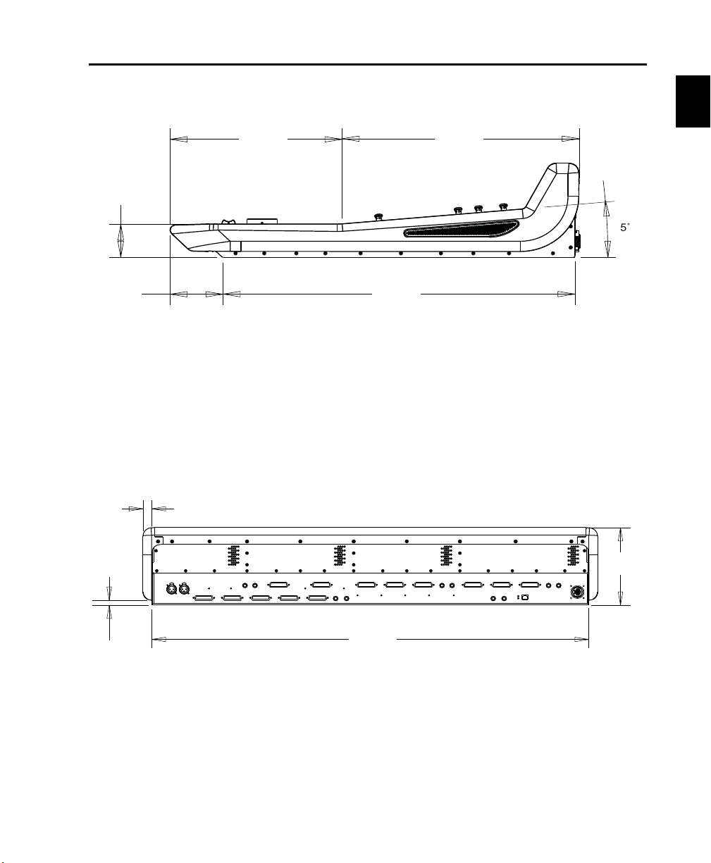
Mechanical Specifications
12.5 in
(31.8 cm)
17.3 in
(43.9 cm)
25.6 in
(65.1 cm)
2.56 in
(6.5 cm)
3.86 in
(9.8 cm)
39.4 in
(100 cm)
7.3 in
(18.5 cm)
0.45 in
(1.16 cm)
0.79 in
(2 cm)
C|24 side dimensions
C|24 back dimensions
Chapter 1: Welcome to C|24 5
Page 14
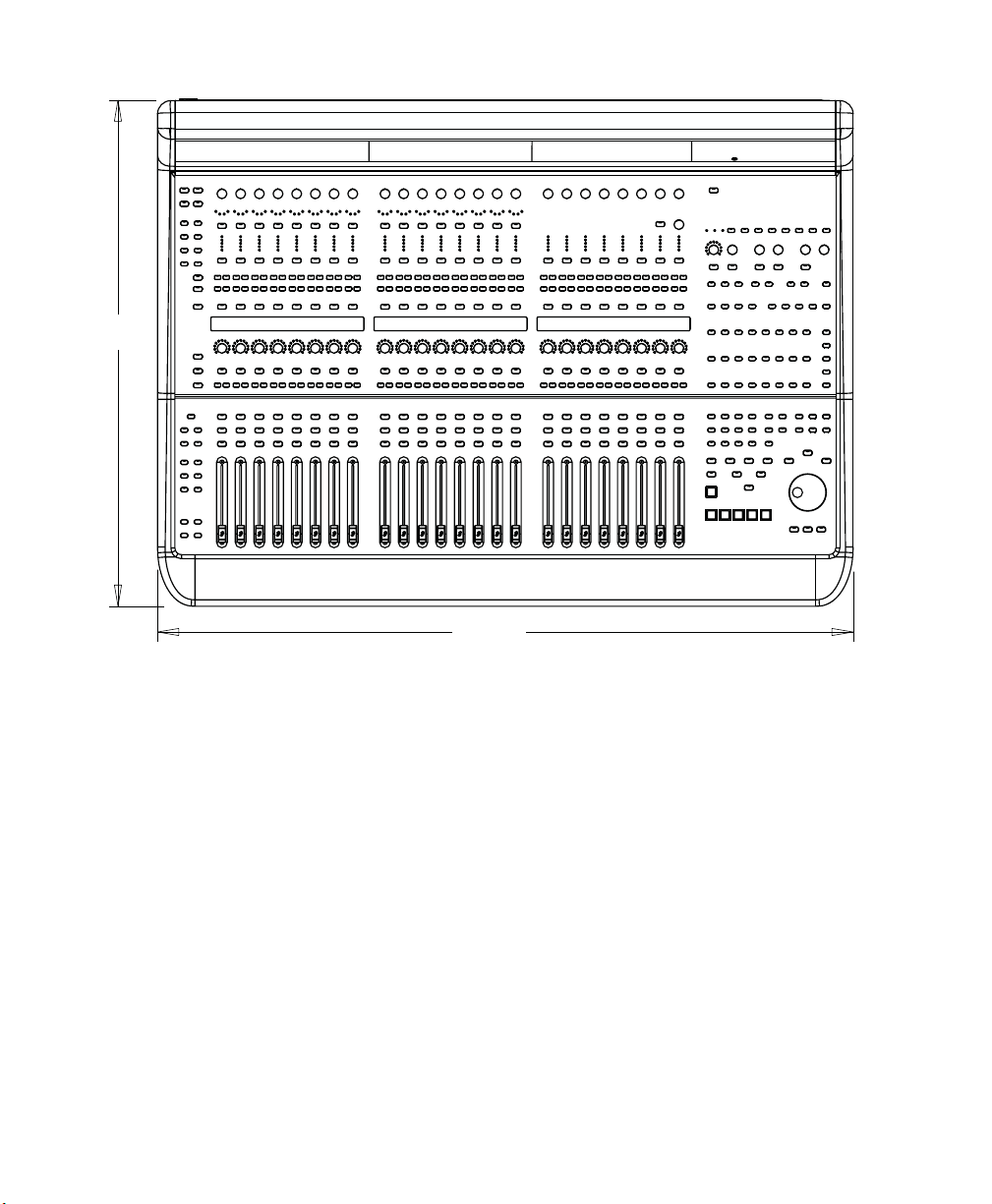
40.9 in
(104 cm)
29.8 in
(75.7 cm)
C|24 top dimensions
C|24 Guide6
Page 15

Connection Requirements
Power Connections
C|24 includes an external power supply that is
auto power-selecting (90-250V, 50-60 Hz) and
will work automatically when plugged into an
AC power receptacle in any country.
Make sure your power source is correctly rated
for all of the components of your system. A
surge-protected power source (not included) is
highly recommended.
Audio Connections
The analog audio inputs and outputs for the
mic/line/DI preamplifiers and the monitoring
section, and the inputs for the built-in submixer
on C|24 are DB-25 connectors.
Four alternate connectors for DI inputs, alter-
nate (stereo) outputs for the monitoring section,
and the outputs for the built-in submixer on
C|24 are 1/4-inch connectors.
For more information on audio connections, see
Appendix A, “C|24 Connector Pinouts.”
Audio Cables for C|24 Monitoring
Ethernet Connections
C|24 communicates with Pro Tools using
Ethernet.
If C|24 is the only Ethernet device you are us-
ing with your computer, you can connect it directly to the Ethernet port on the computer.
If you are using other Ethernet devices (such
as a connection to a Local Area Network) in addition to C|24, an Ethernet hub (not included) is
required.
Digidesign offers a range of DigiSnake cabling
options for connecting Digidesign interfaces
and external sources to the C|24.
For more information on DigiSnake audio
cables, visit the Digidesign website
(www.digidesign.com).
Digidesign Registration
Review the enclosed Digidesign Registration Information Card and follow the instructions on it
to quickly register your purchase online. Registering your purchase is the only way you can be
eligible to receive complimentary technical support and future upgrade offers. It is one of the
most important steps you can take as a new user.
Chapter 1: Welcome to C|24 7
Page 16
About This Guide
About www.digidesign.com
This guide explains how to install and make
connections to your C|24, and how to use it to
access Pro Tools features and commands.
For complete information on using Pro Tools
software, refer to the guides included with your
Pro Tools system.
Conventions Used in This Guide
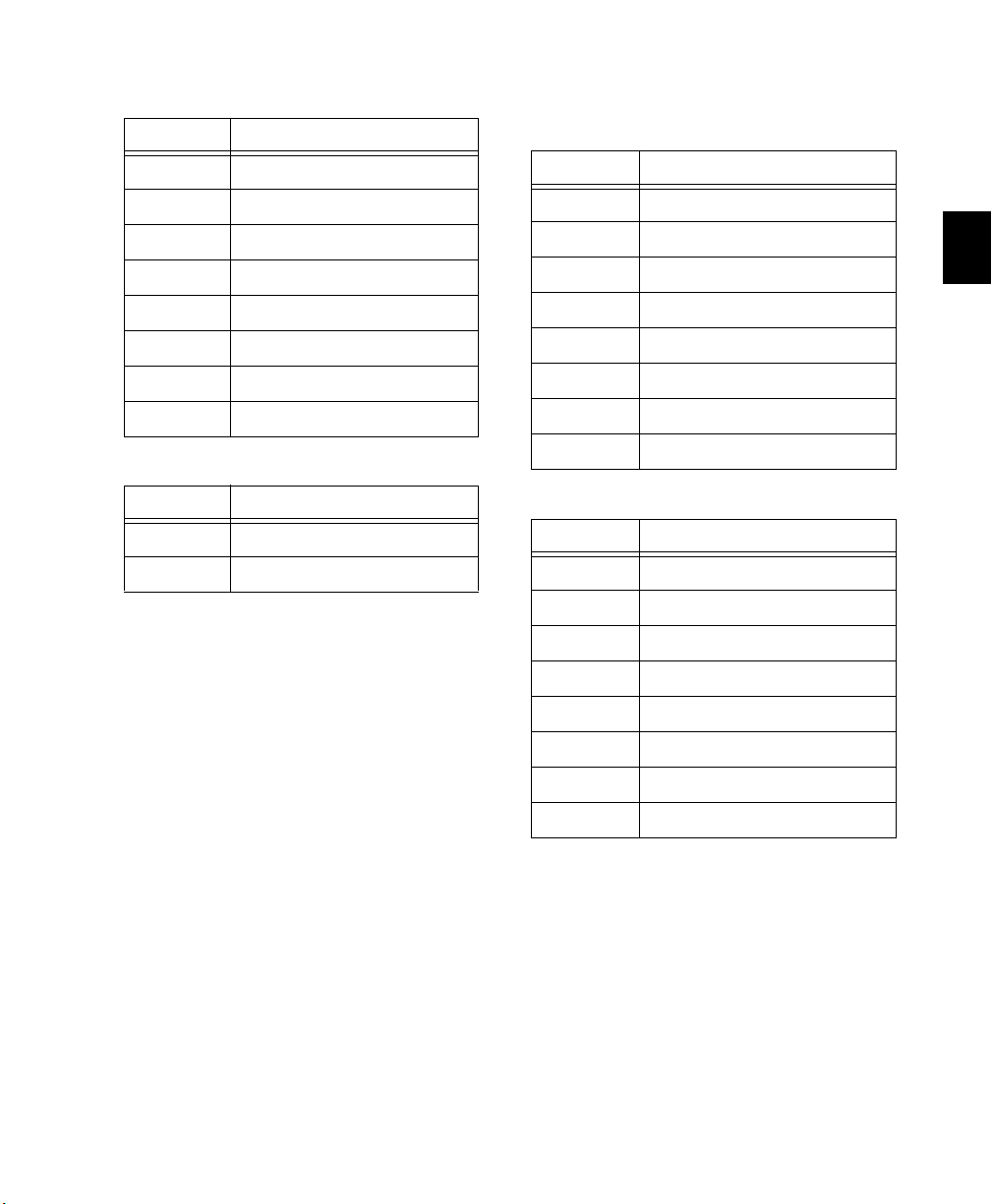
Digidesign guides use the following conventions to indicate menu choices and key commands:
:
Convention Action
File > Save Choose Save from the File
menu
Control+N Hold down the Control key
and press the
Control-click Hold down the Control key
and click the mouse button
Right-click Click with the right mouse
button
The following symbols are used to highlight important information:
N key
The Digidesign website (www.digidesign.com) is
your best source for information to help you get
the most out of your Pro Tools system. The following are just a few of the services and features
available.
Registration Register your purchase online. See
the enclosed Digidesign Registration Information Card for instructions.
Support Contact Digidesign Technical Support
or Customer Service; download software updates and the latest online manuals; browse the
Compatibility documents for system requirements; search the online Answerbase; join the
worldwide Pro Tools community on the Digidesign User Conference.
Training and Education Become a certified
Pro Tools Operator or Expert; study on your
own using courses available online, or find out
how you can learn in a classroom setting at a
certified Pro Tools Training Center.
Products and Developers Learn about Digidesign
products; download demo software; learn about
our Development Partners and their plug-ins,
applications, and hardware.
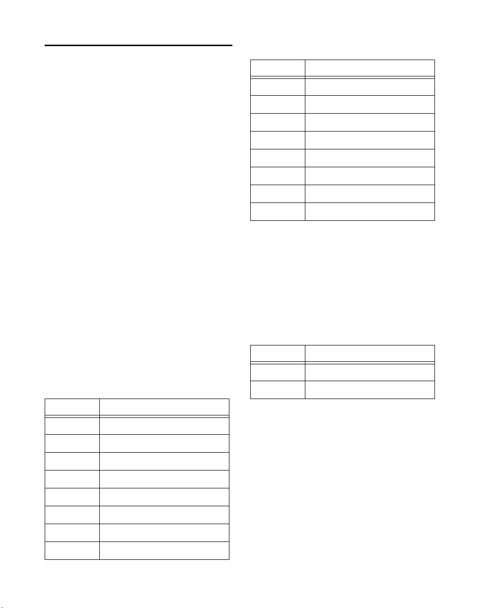
User Tips are helpful hints for getting the
most from your system.
Important Notices include information that
could affect your data or the performance of
your system.
Shortcuts show you useful keyboard or
mouse shortcuts.
Cross References point to related sections in
this guide and other Digidesign guides.
C|24 Guide8
News and Events Get the latest news from
Digidesign; sign up for a Pro Tools demo.
To learn more about these and other resources
available from Digidesign, visit the Digidesign
website (www.digidesign.com).
Page 17
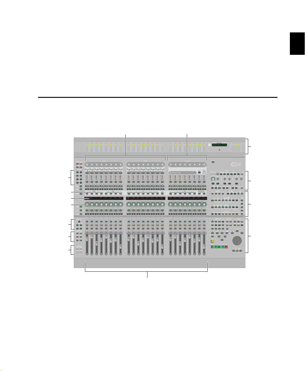
Chapter 2: C|24 Overview
Meter Bridge
Monitor
section
Transport and
Navigation
controls
Fader section
Mic/Line/DI Preamplifier controls Line Submixer
Miscellaneous
controls
Auto Enable
switches
Channel Bar
Modifier
switches
LCD displays
Rotary Encoders
Auto Mode
switches
Auto Write To
switches
C|24 Top Panel
Figure 1. C|24 top panel
Chapter 2: C|24 Overview 9
Page 18

Meter Bridge
Transport and Navigation Controls
The Meter Bridge features a six-channel output
meter, 24 pairs of channel meters, a Pro Tools
Main Counter display, and a built-in Talkback
microphone.
Mic/Line/DI Preamplifier Controls
C|24 includes 16 analog Mic/Line preamplifiers,
with phantom power capability and a switchable high-pass filter. Four channels have available 1/4-inch inputs connectors that override
the DB-25 inputs.
Line Submixer
C|24 also includes an analog line submixer with
8 stereo inputs and a stereo output that can be
used to integrate analog studio equipment into
your studio. The external output of the submixer can be can be routed to a Pro Tools audio
interface. Line submixer output can also be
routed internally to the Monitoring section.
Monitor Section
The Control Room Monitor section provides
two selectable input sources, Main and Alt (both
supporting up to 5.1 Surround); and two selectable outputs, Main (supporting 5.1, LCRS or Stereo monitoring modes) and Alt (supporting Stereo monitoring only). It also provides Cue mix
output, Studio LS output, and full Talkback and
Listenback capability to facilitate studio communication.
Miscellaneous Controls
C|24 provides one-touch access to Pro Tools Edit
modes, Edit tools, MIDI commands and operations, Pro Tools windows, Groups, Memory Locations, Window Configurations, and a range of
powerful global controls that let you apply operations to multiple tracks.
C|24 gives you full control of Pro Tools transport functions with one-touch access to a range
of audition functions, plus dedicated switches
for multiple playback and recording modes. The
Scrub /Shuttle wheel and Navigation key quadrant allow quick navigation in Pro Tools.
Channel Bar
The Channel Bar provides powerful controls for
viewing, assigning, and editing Inputs, Outputs,
Inserts, Sends, Pan controls, plug-in parameters,
Digidesign PRE settings, and C|24 settings.
LCD Displays
Three multi-purpose 55x2 LCD displays provide
access to a range of track information, Channel
Bar functions, Soft Key commands, and C|24
settings.
Rotary Encoders
Twenty-four multi-purpose rotary encoders let
you view and control volume and pan values,
edit plug-in parameters, and make assignments.
Automation Controls
C|24 includes dedicated controls for setting the
automation mode of individual channels, for
enabling and suspending automation types, and
setting the global automation mode.
Fader Section
Twenty-four 100mm touch-sensitive, motorized
faders allow precise control and automation of
track volume. Flip mode lets you control additional Pro Tools parameters from the faders.
C|24 Guide10
Page 19
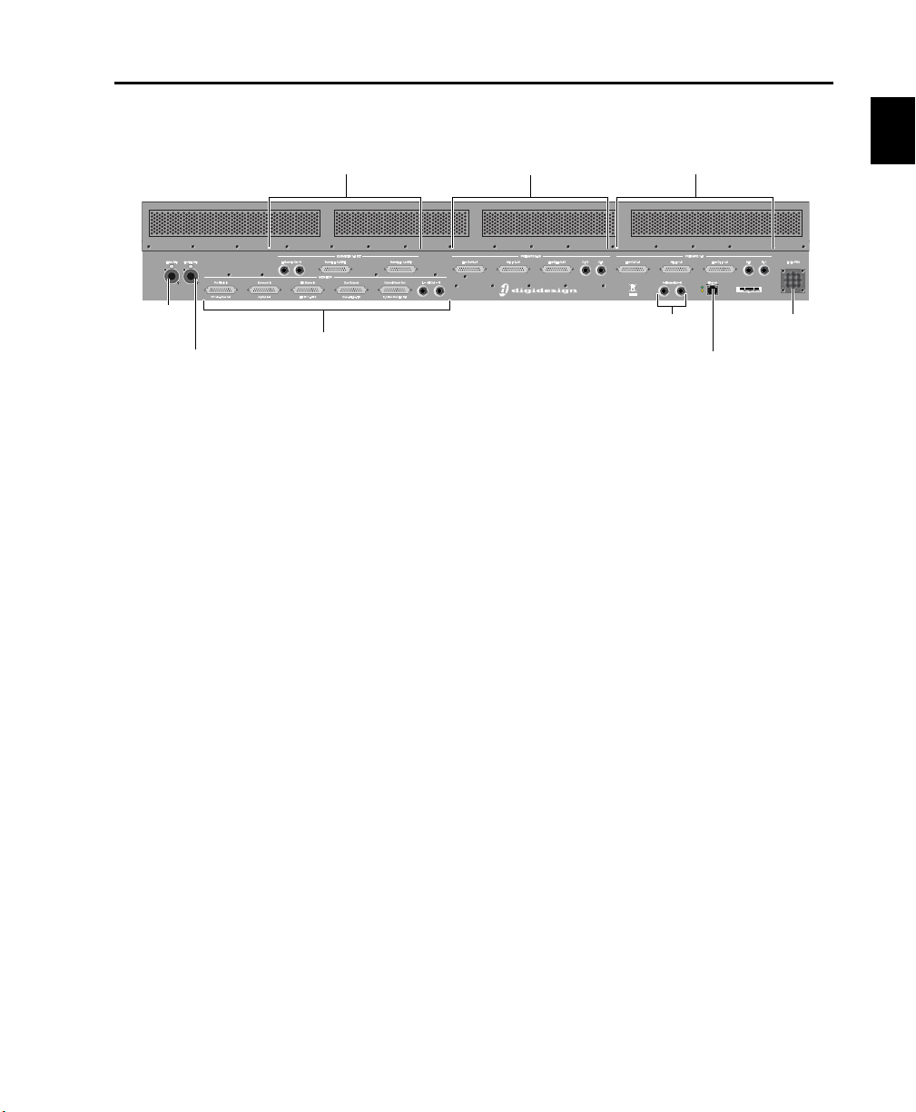
C|24 Back Panel
Monitor section
Submixer section
Preamps 9-16 section
Preamps 1-8 section
Footswitch
connectors
Ethernet
connector
Power Supply
connector
Ext Talk Mic
connector
Listen Mic
connector
Figure 2. C|24 back panel
Submixer Section
Two DB-25 female connectors allow connection
of a total of 16 channels (8 stereo inputs). Stereo
output is available on 1/4-inch TRS connectors.
Preamp Sections
Each of the two 8-channel preamp sections has
two DB-25 female connectors that provide separate, switchable Mic and Line inputs, plus two
alternate 1/4-inch TRS connectors. A third
DB-25 connector in each section provides
preamp outputs.
Monitor Section
Five DB-25 female connectors allow connection
of two six-channel inputs, two stereo inputs,
and a pair of cue inputs. Outputs include a sixchannel Main output, stereo Alt Output (also
available on 1/4-inch TRS connectors), stereo LS
and Cue outputs, and a Talkback Slate output.
Listen Mic and External Talkback Mic
Connectors
Two XLR microphone connectors allow connection of a Listenback microphone and an optional external Talkback microphone.
Footswitch Connectors
Two 1/4-inch TRS footswitch connectors can be
assigned independently to control Pro Tools recording punch in/out, Pro Tools transport
start/stop, or C|24 talkback on/off.
Ethernet Connector
C|24 communicates with Pro Tools using
Ethernet. This connection uses a standard RJ45
connector.
Power Supply Connector
C|24 comes with a dedicated external power
supply that connects to this port.
Chapter 2: C|24 Overview 11
Page 20

C|24 Guide12
Page 21

Part II: Installation
13
Page 22

14
Page 23

Chapter 3: Installing and Configuring C|24
Installing C|24
C|24 can be set on a level table top or mounted
in a console or desk.
Wherever you install C|24, make sure not to
block air circulation to the vents on the back of
the unit.
Connecting Power to C|24
C|24 comes with a dedicated external power
supply that has an IEC standard AC receptacle.
This connector accepts a standard AC power
cable.
To connect power to C|24:
1 Connect the external power supply to the
connector marked “To Ext PSU” on the back
panel of C|24. Make sure the connector is oriented correctly before securing the connection.
2 Connect the included AC power cord to the
external power supply.
Connecting C|24 to the Computer
C|24 communicates with Pro Tools using
Ethernet. This connection uses a standard RJ45
connector.
If you are connecting C|24 directly to your
computer, use a crossover Ethernet cable (one is
included with C|24).
If you are connecting C|24 to an Ethernet hub
or network, use a standard Ethernet cable (not
included).
If C|24 will be the only Ethernet device connected
to your computer:
1 Connect one end of the included crossover
Ethernet cable to the Ethernet port on the back
panel of C|24.
2 Connect the other end of the crossover Ether-
net cable to the appropriate Ethernet port on the
computer.
3 Connect the other end of the AC power cord
to a power source.
Chapter 3: Installing and Configuring C|24 15
Page 24

If you have more than one Ethernet device in
addition to C|24:
1 Connect one end of a standard Ethernet cable
(not included) to the Ethernet port on the back
panel of C|24.
2 Connect the other end of the Ethernet cable
to a powered Ethernet hub (do not use any port
labeled for LAN connection).
3 Connect the Ethernet hub to the appropriate
Ethernet port on the computer.
Shut down your system in this order:
1 Turn off monitor amplifiers or self-powered
speakers.
2 Turn off all Pro Tools audio interfaces.
3 Shut down the computer.
4 If you are using MIDI equipment, turn off
MIDI interfaces and other MIDI devices.
5 Turn off the C|24.
6 Turn off external hard drives.
Starting Up and Shutting Down a Pro Tools System
Your C|24-based Pro Tools system should be
started up and shut down in a specific order.
Start your system in this order:
1 Turn on external hard drives first. Wait 10 to
15 seconds for them to come up to speed.
2 Turn on the C|24.
3 If you plan to work with MIDI equipment,
turn on MIDI interfaces and other MIDI devices.
4 Turn on all Pro Tools audio interfaces.
5 Turn on the computer.
6 Turn on monitor amplifiers or self-powered
speakers.
Configuring C|24
All C|24 software is included when Pro Tools
software is installed. The Pro Tools installer
places the C|24 Personality file in the Controllers folder inside the Pro Tools folder.
Refer to the Getting Started Guide that came with
your system for instructions on installing or updating Pro Tools software.
Updating System Firmware
Each release of Pro Tools software includes current C|24 firmware. When you declare a C|24
unit in the Pro Tools Peripherals dialog,
Pro Tools prompts you if a firmware update is
available.
If you are prompted to update firmware, follow
the on-screen instructions to load the latest
firmware to the C|24.
C|24 Guide16
Page 25
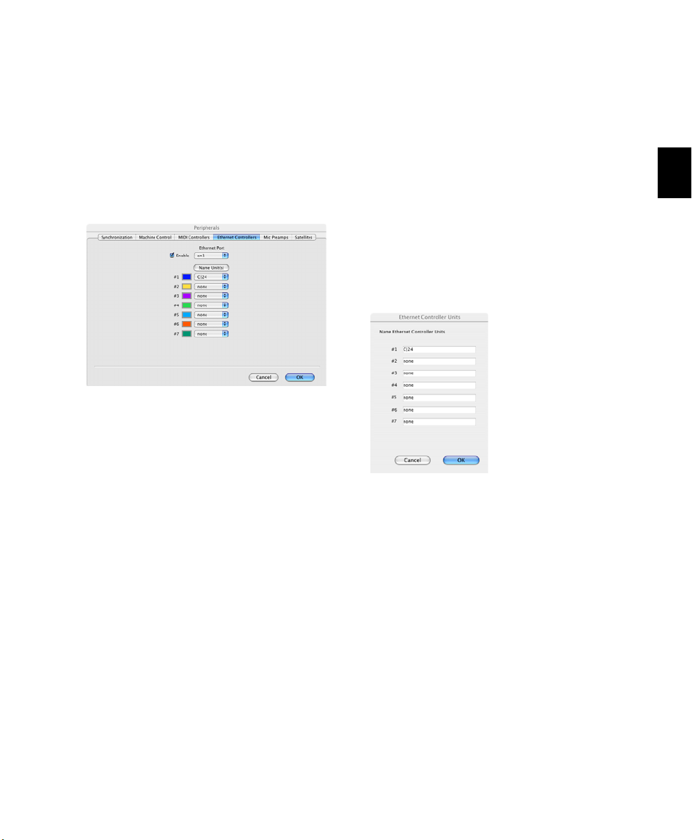
Establishing Communication
Between C|24 and Pro Tools
Communication between C|24 and Pro Tools is
configured by declaring the unit in Pro Tools.
To declare C|24 in Pro Tools:
1 Choose Setup > Peripherals, and click Ethernet
Controllers.
Ethernet Controllers page in the Peripheral dialog
2 Select Enable. Pro Tools scans the Ethernet
connection for any Ethernet controllers connected to the system.
Naming C|24
You can set a name for a C|24 unit so that it can
be easily identified on a network shared with
other Ethernet controllers. You can name C|24
from Pro Tools, or directly from the unit in
Utility Mode.
To name C|24 in Pro Tools:
1 Choose Setup > Peripherals, and click Ethernet
Controllers.
2 Click Name Units. Any declared controllers
will appear in the Ethernet Controller Units
window.
3 Select the C|24 from the pop-up menu for
Controller #1.
If you are connected to a network, any Ethernet
controllers available on the network will be displayed in the pop-up menu, as follows:
Bold text indicates a connected unit.
Italic text indicates an offline or disconnected
unit.
Dimmed text indicates that the selected unit
is in use by another Pro Tools system.
4 Click OK to close the Peripherals dialog.
When communication is established, Pro Tools
displays colored outlines identifying the tracks
focused on C|24.
Naming the C|24
3 Enter the name for the C|24 and click OK.
4 For information on naming C|24 from the
unit, see “Unit Name” on page 118.
Chapter 3: Installing and Configuring C|24 17
Page 26

Using Additional Control Surfaces
with C|24
When a C|24 is declared in Pro Tools, the use of
additional control surfaces is subject to the following restrictions:
You can use a MIDI-based control surface
(such as a Digidesign Command|8) or another
MIDI-based controller (such as the Digidesign
Surround Panner Option) at the same time as a
C|24. A MIDI control surface will mirror the first
8 channels on C|24.
You cannot use another Ethernet-based con-
trol surface (such as an ICON worksurface, Control|24, or ProControl) at the same time as a
C|24.
You cannot declare more than one C|24 on a
Pro Tools system at a time.
Setting C|24 Preferences
The following operational preferences for C|24
are set from the unit, not from Pro Tools.
Auto Talkback
You can enable Auto Talkback, which automatically turns on the Talkback and Listen microphones when the Pro Tools Transport is
stopped. See “Auto Talkback” on page 120.
Mic Pre Clip Hold Time
You can set the Clip Hold time for the C|24
built-in mic/line/DI preamplifiers. See “Mic Pre
Clip Hold” on page 117.
Footswitch Function
You can set the function and polarity for the
two Footswitch connectors on C|24. See “Footswitch Function and Polarity” on page 117.
Console Preferences
You can set the behavior of C|24 displays and
controls and how they interact with Pro Tools.
See “Console Preferences” on page 47.
External Talkback Microphone
You can choose to use an external Talkback microphone instead of the built-in Talkback microphone in the C|24 Meter Bridge. See “External
Talkback Microphone” on page 116.
Talkback Latching
You can set Talkback to latch on when the Talkback switch is double-pressed. See “Talkback
Latching” on page 116.
C|24 Guide18
Page 27

Chapter 4: Audio Connections
C|24 offers versatile analog audio features for
routing audio to and from Pro Tools and other
audio equipment in your studio.
The Mic/Line/DI preamplifiers, built-in Line
Submixer, and Monitor section operate independently of Pro Tools and can be used whenever C|24 is powered on.
Mic/Line/DI Preamplifiers
C|24 provides 16 Mic/Line/DI preamplifiers that
can be used to route input signals to a Pro Tools
audio interface for recording. The Mic/Line/DI
inputs and outputs appear on the C|24 back
panel in six DB-25 connectors.
Audio connectors for the built-in Mic/Line/DI
preamplifiers, Submixer, and Monitor section
are provided on the back panel of C|24.
This chapter provides a summary of the available audio connections to C|24. For detailed pinout tables, see Appendix A, “C|24 Connector
Pinouts.” For example studio connections, see
Chapter 5, “Connecting Your Studio.”
The Mic/Line/DI preamplifiers operate independently of Pro Tools and can be used whenever
C|24 is powered on.
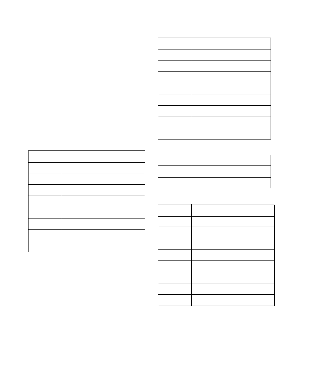
Mic/Line/DI Preamp Inputs
Mic/Line Inputs C|24 Mic/Line/DI preamplifier
inputs appear in two groups of 8 balanced inputs (1-8, 9-16) on the back panel. Each group of
inputs has separate DB-25 female connectors for
mic level and line level inputs, labeled as follows:
•Mic In 1-8
•Line/DI In 1-8
•Mic In 9-16
•Line/DI In 9-16
The input source (Mic or Line) can be selected
individually for each channel using the
Mic/Line/DI preamplifier controls on the top
panel of C|24.
Chapter 4: Audio Connections 19
Page 28
Alternate 1/4-inch connectors C|24 input channels 1, 2, 9, and 10 also have alternate 1/4-inch
balanced TRS connectors on the back panel, labeled as follows:
•DI 1
•DI 2
•DI 9
•DI 10
Line In 1-8
Channel Signal
1 Line In 1
2 Line In 2
3 Line In 3
4 Line In 4
When a source is plugged into a DI input
(1, 2, 9, or 10), the corresponding Mic/Line input (1,2,9,or10) becomes unavailable.
Mic/Line/DI preamplifier inputs are shown in
the following tables.
Mic In 1-8
Channel Signal
1Mic In 1
2Mic In 2
3Mic In 3
4Mic In 4
5Mic In 5
6Mic In 6
7Mic In 7
8Mic In 8
5 Line In 5
6 Line In 6
7 Line In 7
8 Line In 8
DI In 1-2 (overrides Mic/Line In 1-2)
Channel Signal
1 Line In 1
2 Line In 2
Mic In 9-16
Channel Signal
1Mic In 9
2Mic In 10
3Mic In 11
4Mic In 12
5Mic In 13
6Mic In 14
7Mic In 15
8Mic In 16
C|24 Guide20
Page 29
Line In 9-16
Channel Signal
1 Line In 9
2 Line In 10
3 Line In 11
4 Line In 12
5 Line In 13
6 Line In 14
7 Line In 15
8 Line In 16
DI In 9-10 (overrides Mic/Line In 9-10)
Channel Signal
1 Line In 9
2 Line In 10
Line Outputs
Line Out 1-8
Channel Signal
1Line Out 1
2Line Out 2
3Line Out 3
4Line Out 4
5Line Out 5
6Line Out 6
7Line Out 7
8Line Out 8
Line Out 9-16
Channel Signal
1Line Out 9
2Line Out 10
Mic/Line/DI Preamp Outputs
C|24 Mic/Line/DI preamplifier outputs appear
in two groups of 8 line-level outputs (1-8, 9-16)
on the back panel. Each group of outputs has a
DB-25 female connector, labeled as follows:
•Line Out 1-8
• Line Out 9-16
Mic/Line/DI preamplifier outputs are shown in
the following tables.
3Line Out 11
4Line Out 12
5Line Out 13
6Line Out 14
7Line Out 15
8Line Out 16
Chapter 4: Audio Connections 21
Page 30
Line Submixer
C|24 provides an 8x2 Line Submixer that can be
used to mix instrument inputs, auxiliary returns, or other external sources to stereo.
The output of the Line Submixer can then be
connected to Pro Tools audio interface inputs
for recording, or it can be monitored through
the Monitor section of C|24.
Submix In 5-8
Channel Signal
1 Submixer Input 5 (Left)
2 Submixer Input 5 (Right)
3 Submixer Input 6 (Left)
4 Submixer Input 6 (Right)
5 Submixer Input 7 (Left)
The built-in Line Submixer operates independently of Pro Tools and can be used whenever
C|24 is powered on.
Line Submixer Inputs
C|24 Line Submixer inputs appear as two groups
of 4 stereo inputs (1-4, 5-8) on the back panel.
Each group of stereo inputs has a DB-25 female
connector, labeled as follows:
• Submix In 1-4 (ST)
• Submix In 5-8 (ST)
Each of the 8 submixer inputs has an independent gain control on the top panel.
Line Submixer input connections are shown in
the following tables.
Submix In 1-4
Channel Signal
1 Submixer Input 1 (Left)
2 Submixer Input 1 (Right)
3 Submixer Input 2 (Left)
4 Submixer Input 2 (Right)
5 Submixer Input 3 (Left)
6 Submixer Input 3 (Right)
6 Submixer Input 7 (Right)
7 Submixer Input 8 (Left)
8 Submixer Input 8 (Right)
Line Submixer Outputs
Stereo Outputs C|24 Line Submixer outputs appear as a pair of line-level outputs (L-R) on the
back panel. Each output has a 1/4-inch balanced
TRS connector, labeled as follows:
•Submix Out L
•Submix Out R
Submix Out 1-2
Channel Signal
1 Submix Out (Left)
2Submix Out (Right)
Stereo Output to Monitor Section C|24 Submixer outputs (L-R) can also be routed to the
Left and Right channels of the C|24 Monitor section using the “To Mon” switch on the top
panel of C|24. This is useful for monitoring your
studio equipment when you are not running
Pro Tools.
The submixer output level is controlled with the
Master level control on the top panel.
7 Submixer Input 4 (Left)
8 Submixer Input 4 (Right)
C|24 Guide22
Page 31

Monitor Section
The C|24 Monitor section is a six-channel control room monitoring system that allows connection of up to four input sources (two 6-channel or 4-channel surround, and two stereo), two
cue inputs, and two outputs (one 6-channel surround and one stereo).
Monitor section Inputs are connected to
Pro Tools audio interface outputs and other input sources in your studio. Monitor section Outputs are connected to your speakers, cue system,
headphones, and studio talkback and listenback
systems.
The Monitor section operates independently of
Pro Tools and can be used to monitor other input sources whenever C|24 is powered on.
Monitor Section Inputs
C|24 Monitor section inputs appear on three
DB-25 female connectors on the back panel,
labeled as follows:
• Pro Tools In (PT 1-6 + Cue 1-2)
• Surround In (Alt Sur 1-6)
• Ext Stereo In (Ext St 1 + St 2)
Input sources can be selected individually or
summed using the Monitor source switches on
the top panel of C|24.
Monitor section input connections are shown in
the following tables.
Pro Tools In (PT 1-6 + Cue 1-2)
Main Inputs Connect the outputs from your
Pro Tools system to the Main Inputs.
Cue Inputs Connect cue outputs from your
Pro Tools system (such as a Send-based cue mix
routed to audio interface outputs) to the Cue Inputs.
Pro Tools In (PT 1-6 + Cue 1-2)
Channel Signal
1 Main Input Left (L)
2 Main Input Center (C)
3 Main Input Right (R)
4 Main Input Left Surround (Ls)
5 Main Input Right Surround (Rs)
6 Main Input LFE (LFE)
7 Cue Input Left
8 Cue Input Right
Surround In (Alt Sur 1-6)
Alternate Surround Inputs Connect an alternate
input source (up to 5.1 surround) to the Alt Sur
(Alternate Surround) Inputs.
Surround In (Alt Sur 1-6)
Channel Signal
1 Alt Input Left (L)
2 Alt Input Center (C)
3 Alt Input Right (R)
4 Alt Input Left Surround (Ls)
5 Alt Input Right Surround (Rs)
6 Main Input LFE (LFE)
7 (Unused)
8 (Unused)
Chapter 4: Audio Connections 23
Page 32

Ext Stereo In (Ext St 1 + St 2)
Control Room Out (5.1 Mon Out L:1 R:3)
External Stereo Inputs Connect external stereo
sources (such as a DAT or CD player) to the External Stereo Inputs.
Ext Stereo In (Ext St 1 + St 2)
Channel Signal
1 Ext Stereo 1 In Left
2 Ext Stereo 1 In Right
3 Ext Stereo 2 In Left
4 Ext Stereo 2 In Right
5 (Unused)
6 (Unused)
7 (Unused)
8 (Unused)
Monitor Section Outputs
C|24 Monitor section outputs appear on two
DB-25 female connectors on the back panel, labeled as follows:
• Control Room Out (5.1 Mon Out L:1 R:3)
• Cue Outputs (Cue + SLS + TB)
Main Outputs Connect the Main Outputs to
your primary studio monitors (tables are shown
below for 5.1, LCRS and Stereo Main monitor
setups).
Alternate Outputs Connect the Alternate Outputs to a secondary pair of studio monitors. The
Alt Outputs (L-R) are also available on 1/4-inch
balanced TRS connectors on the back panel, and
mirror the output signal on the Alt Outputs on
the Control Room Out connector.
Main Outputs (5.1) and Alternate Outputs
Control Room Out (5.1 Mon Out L:1 R:3)
Channel Signal
1 Main Output Left (L)
2 Main Output Center (C)
3 Main Output Right (R)
4 Main Output Left Surround (Ls)
5 Main Output Right Surround (Rs)
6 Main Output LFE (LFE)
7 Alt (Stereo) Output Left
The Monitor section output mode can be set to
5.1, LCRS, or Stereo using the Monitor mode
switches on the top panel of C|24.
Monitor section output connections are shown
in the following tables.
C|24 Guide24
8 Alt (Stereo) Output Right
Page 33

Main Outputs (LCRS) and Alternate Outputs
Cue Outputs (Cue + SLS +TB)
Control Room Out (5.1 Mon Out)
Channel Signal
1 Main Output Left (L)
2 Main Output Center (C)
3 Main Output Right (R)
4 Surround Output (S)
5 (Unused)
6 (Unused)
7 Alt (Stereo) Output Left
8 Alt (Stereo) Output Right
Main Outputs (Stereo) and Alternate Outputs
Control Room Out (5.1 Mon Out)
Channel Signal
1 Main Output Left (L)
2 (Unused)
3 Main Output Right (R)
Cue Outputs Connect the Cue Outputs to the inputs of your cue system.
Studio LS Outputs Connect Studio LS Outputs to
speakers in your live room.
Talkback Slate Output Connect the Talkback
Slate Output to an available Pro Tools input to
record slate information.
Cue Outputs (Cue + SLS + TB)
Channel Signal
1 Cue Out Left
2Cue Out Right
3 Studio LS Out Left
4 Studio LS Out Right
5 Talkback Slate Out
6 (Unused)
7 (Unused)
8 (Unused)
4 (Unused)
5 (Unused)
6 (Unused)
7 Alt (Stereo) Output Left
8 Alt (Stereo) Output Right
Alternate Outputs (Stereo)
Alt Outputs (Alt Out L-R on 1/4-inch TRS connectors)
Chan Signal
1 Alt (Stereo) Output Left
2 Alt (Stereo) Output Right
Chapter 4: Audio Connections 25
Page 34

Listen and Talkback Microphones
C|24 provides connectors for a Listen microphone and an optional External Talkback microphone.
Listen Mic This XLR connector lets you connect
a microphone to provide two-way communication between the studio and the control room.
External Talkback Mic This XLR connector lets
you connect an external microphone to use in
place of the built-in Talkback microphone. Talkback input is selected in the Talkback Preferences in Utility mode. See “External Talkback
Microphone” on page 116.
For more information on the Talkback function,
see “Talkback Switch” on page 59.
Headphone Output
C|24 provides a headphone output with a 1/4inch TRS connector on the front of the unit.
Headphone source is switchable between Control Room outputs L and R (channels 1 and 3,
pre-fader) and the Cue send (post-fader).
C|24 Guide26
Page 35

Chapter 5: Connecting Your Studio
Connection Examples for Stereo Monitoring
You can set up a basic stereo monitoring system
using 2-channel input from Pro Tools. This input can be monitored on channels 1 (Left) and 3
(Right) of the C|24 Main Monitor outputs, or in
the C|24 Alt Monitor (Stereo) outputs.
Another stereo source can be monitored by connecting it to channels 1 (Left) and 3 (Right) of
the Alternate Surround Inputs.
Additional stereo sources can be monitored by
connecting them to the External Stereo 1 and 2
Inputs.
You can also connect a separate cue send from
Pro Tools, and route it to the C|24 cue system
outputs.
The following tables and diagram show examples of connections for stereo monitoring.
Chapter 5: Connecting Your Studio 27
Page 36

Monitoring System Inputs
Monitoring System Outputs
Main Inputs and Cue Inputs
Pro Tools In (PT 1-6 + Cue 1-2)
Chan Signal
1 Main Input Left (L) from Pro Tools Out 1
2 no connection
3 Main Input Right (R) from Pro Tools Out 2
4 no connection
5 no connection
6 no connection
7 Cue Input Left from Pro Tools Cue Out 1
8 Cue Input Right from Pro Tools Cue Out 2
Alternate Inputs
Surround In (Alt Sur 1-6)
Chan Signal
1 Alt Input Left (L)
2 no connection
3 Alt Input Right (R)
4 no connection
5 no connection
6 no connection
External Stereo Inputs
Main Outputs (Stereo) and Alternate Outputs
Control Room Out (5.1 Mon Out L:1 R:3)
Chan Signal
1 Main Output Left (L) to Main speaker L
2 no connection
3 Main Output Right (R) to Main speaker R
4 no connection
5 no connection
6 no connection
7 Alt (Stereo) Output Left to Alt speaker L
8 Alt (Stereo) Output Right to Alt speaker R
Alt Outputs (Alt Out L-R on 1/4-inch TRS connectors)
Chan Signal
1 Alt (Stereo) Output Left to Alt speaker L
2 Alt (Stereo) Output Right to Alt speaker R
Cue Outputs
Cue Outputs (Cue + SLS + TB)
Channel Signal
1 Cue Out Left to cue system
2 Cue Out Right to cue system
Ext Stereo In (Ext St 1 + St 2)
Chan Signal
1 Ext Stereo 1 In Left from CD player
2 Ext Stereo 1 In Right from CD player
3 Ext Stereo 2 In Left from DAT deck
4 Ext Stereo 2 In Right from DAT deck
C|24 Guide28
Page 37

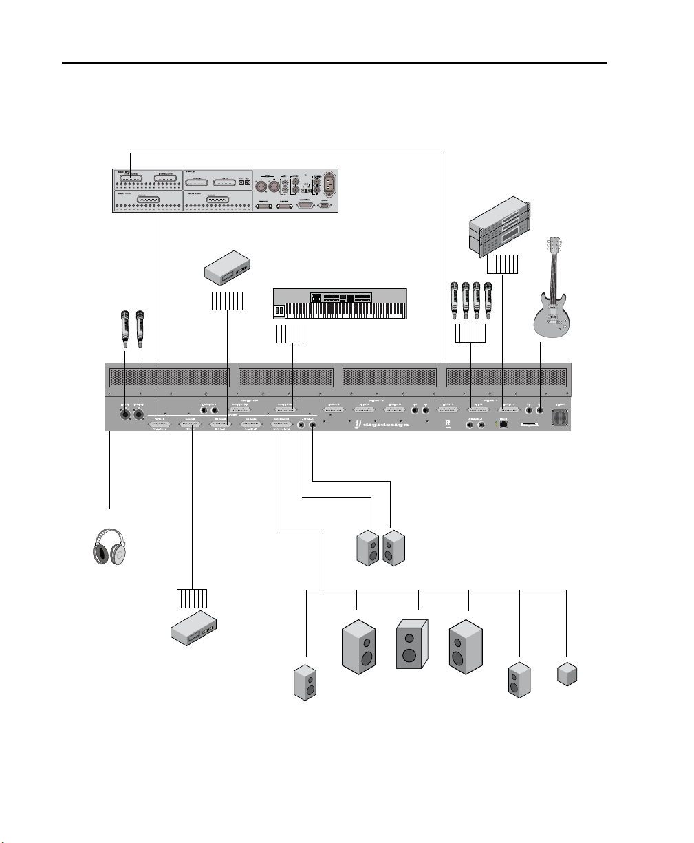
Pro Tools In
Headphone Out
DIMic In Line In
Preamp Line Out
C|24
Line Submixer InExt Stereo In
Monitor Alt Out
Monitor
to Pro Tools
Cue Out
Main Out
Ch 1,3
003
Rack
L
R
Pro Tools
Stereo Out 1-2
Cue Out 1-2
Submixer
Out
Alternate speakers
Main speakers
Cue system
CD player
or DAT deck
Stereo Studio Connections
(Example Setup)
Example studio setup with stereo monitoring
Chapter 5: Connecting Your Studio 29
Page 38

Connection Examples for Surround Monitoring
You can set up a surround monitoring system
using up to 6-channel input from Pro Tools.
5.1, LCRS, or Stereo input can be monitored in
the C|24 Main Monitor outputs. Stereo input
can also be monitored in the C|24 Alt Monitor
(Stereo) outputs.
An additional surround source can be monitored by connecting it to the Alternate Surround
Inputs.
External stereo sources can be monitored by
connecting them to the External Stereo 1 and 2
Inputs.
You can also connect a separate cue send from
Pro Tools, and route it to the C|24 cue system
outputs.
The following tables and diagram show examples of connections for surround monitoring.
C|24 Guide30
Page 39

Monitoring System Inputs
Monitor Inputs and Cue Inputs
Pro Tools In (PT 1-6 + Cue 1-2)
Chan Signal
1 Main Input Left (L) from Pro Tools Out 1
2 Main Input Center (C) from Pro Tools Out 2
3 Main Input Right (R) from Pro Tools Out 3
4 Main Input L Surr (Ls) from Pro Tools Out 4
5 Main Input R Surr (Rs) from Pro Tools Out 5
6 Main Input LFE (LFE) from Pro Tools Out 6
7 Cue Input Left from Pro Tools Cue Out 1
8 Cue Input Right from Pro Tools Cue Out 2
Monitoring System Outputs
Main Outputs (5.1) and Alternate Outputs
Control Room Out (5.1 Mon Out L:1 R:3)
Chan Signal
1 Main Output Left (L) to Left speaker
2 Main Output Center (C) to Center speaker
3 Main Output Right (R) to Right Speaker
4 Main Output Left Surround (Ls) to Left
Surround speaker
5 Main Output Right Surround (Rs) to Right
Surround speaker
6 Main Output LFE (LFE) to Subwoofer
7 Alt (Stereo) Output Left to Alt speaker L
Alternate Surround Inputs
Surround In (Alt Sur 1-6)
Chan Signal
1 Alt Input Left (L) from DVD player
2 Alt Input Center (C) from DVD player
3 Alt Input Right (R) from DVD player
4 Alt Input Left Surround (Ls) from DVD
player
5 Alt Input Right Surround (Rs) from DVD
player
6 Alt Input LFE (LFE) from DVD player
External Stereo Inputs
Ext Stereo In (Ext St 1 + St 2)
Chan Signal
1 Ext Stereo 1 In Left from CD player
2 Ext Stereo 1 In Right from CD player
3 Ext Stereo 2 In Left from DAT deck
4 Ext Stereo 2 In Right from DAT deck
8 Alt (Stereo) Output Right to Alt speaker R
Main Outputs (LCRS) and Alternate Outputs
Control Room Out (5.1 Mon Out L:1 R:3)
Chan Signal
1 Main Output Left (L) to Left speaker
2 Main Output Center (C) to Center speaker
3 Main Output Right (R) to Right Speaker
4 Main Output Left Surround (Ls) to Surround
speaker (or split to 2 Surround speakers)
5 no connection
6 no connection
7 Alt (Stereo) Output Left to Alt speaker L
8 Alt (Stereo) Output Right to Alt speaker R
Alternate Outputs (Stereo)
Alt Outputs (Alt Out L-R on 1/4-inch TRS connectors)
Chan Signal
1 Alt (Stereo) Output Left to Alt speaker L
2 Alt (Stereo) Output Right to Alt speaker R
Chapter 5: Connecting Your Studio 31
Page 40
Pro Tools In
Headphone Out
DIMic In Line In
Preamp Line Out
C|24
192 I/O
Line Submixer In
Ext Stereo In
Monitor Alt Out
Monitor
LCR
Ls Rs LFE
to Pro Tools
Ext Talkback
& Listen Mics
Main Out
Ch 1-6
123456
Alt
Surround In
Pro Tools
Ch 1-6 Out
Cue Out 1-2
Alternate speakers
CD player
or DAT deck
DVD player
5.1 Surround Studio Connections
(Example Setup)
Example studio setup with 5.1 surround monitoring
C|24 Guide32
Page 41

Chapter 5: Connecting Your Studio 33
Page 42

C|24 Guide34
Page 43

Part III: Reference
35
Page 44

36
Page 45

Chapter 6: C|24 Pro Tools Controls
Fader
Mute switch
Solo switch
Channel
Record Enable
switch
Encoder switch
Rotary Encoder
LCD display
Send switch
Dyn switch
Automation Mode
Input Monitor
switch
Insert switch
EQ switch
Automation
Select switch
Mode
indicators
switch
Fader Section
Channel Strip
Fader
Each channel has a touch-sensitive motorized
fader for controlling channel volume in Normal
mode and a wide range of parameters in Flip
mode. When you are automating a parameter
on a fader in Touch mode, touching the fader
starts writing automation.
Mute Switch
The Mute switch toggles mute status for the
channel. When a track is muted, its Mute switch
lights solid. When a track is implicitly muted
(because another track is soloed), its Mute
switch flashes.
Solo Switch
The Solo switch toggles solo status for the channel. When a channel is soloed, the Solo switch
lights, and the Mute switches on other channels
in the session flash to indicate implicit mute.
The Solo switch function follows the Pro Tools
Solo Latch options (Latch, X-OR, and Momentary).
Solo Safe Mode To solo safe a track, hold the
Command/Ctrl Modifier switch and press the
track’s Solo switch. When a track is solo safed,
its Solo switch flashes once.
Channel Strip
Chapter 6: C|24 Pro Tools Controls 37
Page 46

Channel Select Switch
Rotary
Encoder
Select/Auto
switch
Pre/Post
switch
Send Mute
switch
Encoder
switch
The Channel Select switch selects the channel in
Pro Tools, and lights when the channel is selected. The Channel Select switch can be set to
follow latching or X-OR (non-latching) behavior. See “Console Preferences” on page 47.
Input Monitor Switch
Rotary Encoder Section
The function of the Input Monitor switch depends on the type of track displayed in the
channel strip.
Audio Tracks (Pro Tools HD Only) The Input
Monitor switch toggles the input monitoring
mode (TrackInput) for the channel between
Auto Input and Input Only mode. When the
channel is in Input Only mode, the Input Monitor switch lights.
Instrument Tracks The Input Monitor switch
transfers control of MIDI Volume to the fader,
MIDI Pan to the rotary encoder, and MIDI Mute
to the channel Mute switch. It also changes Input and Output assign modes to apply to MIDI
Inputs and Outputs on the Instrument track.
When MIDI controls are displayed on the channel fader and encoder, the Input Monitor switch
flashes.
Record Enable Switch
The Record Enable switch toggles record enable
status for the channel. When a track is recordenabled and Pro Tools is idle or playing back,
the Record Enable switch flashes. During recording, the Record Enable switch lights continuously.
Record Safe Mode To record safe a track, hold
the Command/Ctrl Modifier switch and press
the track’s Record Enable switch.
C|24 Guide38
Rotary Encoder section
Rotary Encoder
Each Channel has a rotary encoder. The function of the rotary encoders depends on the current mode and view.
Console Views Rotary encoders control channel
pan, send level and assignments, depending on
which Console view is enabled (Pan view or
Sends view). If your system includes a Digidesign PRE, mic pre level can be controlled from
the rotary encoders in Console view.
Channel View Rotary encoders control plug-in,
pan, send, or plug-in settings and assignments,
depending on which Channel view is enabled
(Pan/Send view or Insert Select view). If your
system includes a Digidesign PRE, most mic pre
controls can be accessed in Channel View.
Flip Mode Rotary encoders control track Volume
or Send pan position when Flip mode is enabled.
Rotary Encoder LEDs
Each rotary encoder has a ring of 11 LEDs for indicating data values controlled by the encoder.
Discrete or stepped information such as pan position or frequency is shown by a single LED.
Continuously variable values such as send level,
gain, or filter bandwidth are shown by an expanding series of LEDs.
Page 47

Encoder LED rings can show send level, pan position, and plug-in parameter values. In Flip
mode, they can show track level or Send pan position.
Select When the Select/Auto switch is unlit, it is
in Select mode. In this mode, encoder switches
toggle plug-in parameters displayed above the
corresponding encoder.
Encoder Switch
The switches under each encoder perform a variety of functions, depending on what is shown
in the LCD displays. Functions of the encoder
switch include:
• Sends Console view: Toggling Send mute or
Send pre/post status
• Pan/Send Channel view: Toggling Send
mute or Send pre/post status
• Parameter view: Cycling stepped plug-in
parameters, setting up multi-mono plug-in
operation
• Mic Pre view: If your system includes a
Digidesign PRE, controlling mic pre settings
• Groups view: Selecting Group IDs for new
groups, enabling or selecting current
Groups
• Soft Keys view: Cycling preferences or performing actions
• Default switch: Setting parameters to their
default values
• Window Configuration view: Creating, editing, and recalling Window configurations
• Memory Location view: Creating, editing,
and recalling Memory Locations
Switch Functions Section
Auto When the Select/Auto switch is lit, it is in
Auto mode. In this mode, encoder switches do
either of the following:
• If Pro Tools is idle or playing back, the encoder switches enable the corresponding
plug-in parameters for automation. The
switch lights to indicate enabled status.
• If an automation pass is in progress, the encoder switches flash to indicate writing of
plug-in automation. You can press a flashing encoder switch to punch the plug-in
parameter out of writing.
Pre/Post Switch
The Pre/Post switch is available only when C|24
is in Sends Console view.
When the Pre/Post switch is lit, the encoder
switches toggle the corresponding Send between
pre- and post-fader operation. When the encoder switch is unlit, the Send is set to post-fader
operation. When the encoder switch is lit, the
Send is set to pre-fader operation.
When you hold down the Pre/Post switch, the
pre/post status of all Sends is displayed.
Send Mute Switch
The Send Mute switch is available only when
C|24 is in Sends Console view.
The Switch Functions section has three switches
that set the function of the encoder switches in
certain views.
Select/Auto Switch
The Select/Auto switch is available only when
C|24 is in Parameter view.
When the Send Mute switch is lit, the encoder
switches toggle the mute status of the corresponding Send. When the encoder switch is unlit, the Send is not muted When the encoder
switch is lit, the Send is muted.
To view the mute status of all displayed Sends,
hold down the Send Mute switch.
Chapter 6: C|24 Pro Tools Controls 39
Page 48

LED Displays
Display Mode
switch
LED displays
Insert/Send
Bypass
switch
Insert switch
LED displays and Display Mode switch
The LED displays provide two rows of 6 characters for each channel strip.
LED Display Mode Switch
Mem Loc/Win Cfg Mode Shows the track name
on the top row and available Memory Locations
or Window Configurations on the bottom row.
Sends Console View
In Sends Console view, the Display Mode switch
cycles through the following Send display
modes:
Send Path Shows the track name on the top row
and the I/O or bus path for the Send on the bottom row.
To cycle forward through LED display modes:
Press the Display Mode switch.
To cycle backward through the LED display modes:
Hold the Shift (add) Modifier switch and press
the Display Mode switch.
The available display modes depend on the current view.
Home (Pan Console) View
In Pan Console view, the Display Mode switch
cycles through the following channel display
modes:
Name Mode Shows the track name only on the
top row. Volume and Pan values are displayed
on the bottom row when the fader is touched or
the encoder is moved, according to the TchVal
preference.
Vol ume M ode Shows the track name on the top
row and track volume on the bottom row.
Pan Mode Shows the track name on the top row
and track pan on the bottom row.
Send Volume Shows the track name on the top
row and the Send volume on the bottom row.
Blank Shows track name only on the top row.
Channel Information
In any view, you can also press and hold the Display Mode switch to show channel state information, including current view display, LED display data, rotary and fader controls, and plug-in
information.
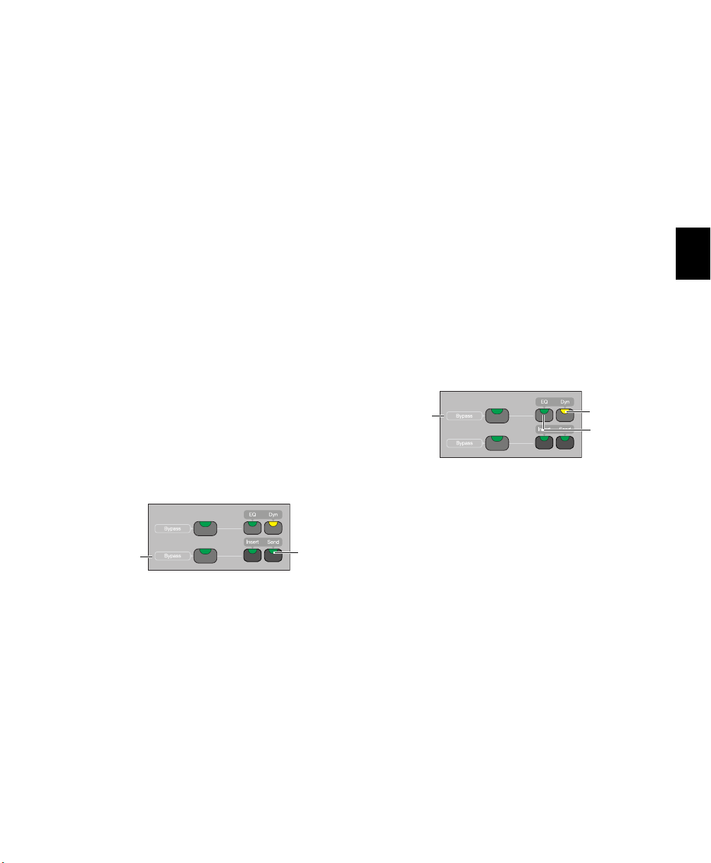
Insert Switch
Insert switch
Each channel has an Insert switch that lets you
select and view inserts on that channel. The
switch lights to indicate that there is at least one
non-EQ, non-Dynamics plug-in on the channel.
Headroom Mode Shows the track name on the
top row and track headroom on the bottom row.
C|24 Guide40
Page 49
When you press a lit Insert switch, C|24 enters
Insert/Send
Bypass
switch
Send switch
Dyn switch
EQ switch
EQ/Dyn
Bypass
switch
Insert Select view, and displays the channel’s inserts across the LCD displays. From Insert Select
view, you can display all the controls of a single
plug-in in Parameter view. See “Insert Select
View” on page 78 and “Parameter View” on
page 80.
In Parameter view, when you press and hold a lit
Insert switch, the LCD displays show information on the currently focused insert.
Insert/Send Bypass Switch
The Insert and Send Bypass switch changes the
function of the Insert switches on all channels,
putting them in Bypass mode. When the Insert/Send Bypass switch is lit, the Insert switch
toggles the Bypass state of all plug-ins on the
channel. In Bypass mode, when the plug-ins on
a track are bypassed, the track’s Insert switch is
lit.
See “Bypassing Plug-ins” on page 79.
When you double-press a Send switch, C|24 enters Expanded Pan view, and displays the pan
controls for a track. See “Expanded Pan View”
on page 75.
Insert/Send Bypass Switch
The Insert and Send Bypass switch changes the
function of the Send switches on all channels,
putting them in Bypass mode. When the Insert/Send Bypass switch is lit, the Send switch
toggles the mute status of all Sends on the channel. In Bypass mode, when the sends on a track
are muted, the track’s Send switch is lit.
See “Muting Sends in Pan/Send Channel View”
on page 74.
EQ and Dynamics Switches
Send Switch
Send switch
Each channel has a Send switch that lets you select and view Sends on that channel.The switch
lights to indicate that there is at least one Send
on the channel.
When you press a lit Send switch, C|24 enters
Pan/Send Channel view, and displays the channel’s Sends across the LCD displays. See
“Pan/Send Channel View” on page 73.
EQ and Dynamics switches
Each channel has EQ and Dynamics switches
that let you focus any plug-ins of the corresponding type assigned to that channel. The EQ
or Dyn switch lights to indicate that there is at
least one plug-in of the corresponding type on
the channel. When you press a lit EQ or Dyn
switch, C|24 enters Parameter view, and displays
the plug-in’s controls across the LCD displays.
See “Viewing EQ and Dynamics Plug-ins” on
page 81.
In Parameter view, when you press and hold a lit
EQ or Dyn switch, the LCD displays show information on the currently focused plug-in.
Chapter 6: C|24 Pro Tools Controls 41
Page 50

EQ and Dynamics Bypass Switch
Automation Mode switch
Automation Mode indicators
Automation
Trim M o d e
switch
Automation
Latch Mode
switch
Automation
Touch Mode
switch
Automation
Write Mode
switch
Automation
Read Mode
switch
Automation
Off
switch
See “Working with Automation” on page 103.
The EQ and Dynamics Bypass switch changes
the function of the EQ and Dynamics switches
on all channels, putting them in Bypass mode.
EQ Switch When the EQ and Dyn Bypass switch
is lit, the EQ switch toggles the Bypass state of all
EQ plug-ins on the channel. In Bypass mode,
when the EQ plug-ins on a track are bypassed,
the track’s EQ switch is lit.
Dynamics Switch When the EQ and Dyn Bypass
switch is lit, the Dyn switch toggles the Bypass
state of all Dynamics plug-ins on the channel. In
Bypass mode, when the Dynamics plug-ins on a
track are bypassed, the track’s Dyn switch is lit.
See “Bypassing EQ and Dynamics Plug-ins” on
page 81.
Channel Automation Mode Switch and
Indicators
The Automation Mode switch lets you cycle the
channel through Touch, Latch, Touch/Latch,
Read and Off modes during playback, but it prevents you from entering Write mode during
playback. To directly enter Write mode during
playback, use the Global Automation Mode
switch (See “Automation Mode Switches” on
page 42.)
When in Write mode, the corresponding indicator flashes at all times. When in Touch, Latch, or
Touch/Latch modes, the corresponding indicator lights until automation writing begins.
When automation writing begins on the channel, the indicator flashes. If automation is
turned off for the channel (Off), none of the indicators is lit.
Global Automation Switches
Automation Mode Switches
Automation Mode switch and indicators
Each channel has an Automation Mode switch
and series of Automation Mode indicators
(Write, Touch, Latch, Trim and Read).
The Automation Mode switch cycles the channel through the following Pro Tools automation
modes:
•Write
•Touch
•Latch
•Touch/Latch (ProToolsHD only)
•Read
•Off
C|24 Guide42
Automation Mode switches
The Automation Mode switches are used to display and set automation modes. These switches
light to indicate that at least one channel is in
that automation mode. If multiple channels are
selected and set to different automation modes,
all applicable mode switches are lit.
Page 51

The Automation Mode switches mirror the
Enable Plug-in
Automation
Enable Send Level
Automation
Enable Send Mute
Automation
Enable Volume
Automation
Enable Pan
Automation
Enable Mute
Automation
Enable Send Pan
Automation
switch
switch
switch
switch
switch
switch
switch
Suspend
Automation
switch
function of the on-screen Automation Mode selector for each track, and let you change automation modes of channels during playback.
See “Working with Automation” on page 103.
Write Switch Indicates or sets the automation
mode of a track to Write mode.
Touch Switch Indicates or sets the automation
mode of a track to Touch mode.
Latch Switch Indicates or sets the automation
mode of a track to Latch mode.
Trim Switch (Pro Tools H D Onl y) Indicates or sets
the automation mode of a track to Trim mode.
Read Switch Indicates or sets the automation
mode of a track to Read mode.
Off Switch Sets the automation mode of a track
to Off.
Automation Enable Switches
When writing is enabled for an automation type
but it is not currently writing on any track in the
session, the corresponding switch lights solid.
When writing is enabled for an automation type
and it is currently writing on any track in the
session, the corresponding switch flashes.
Volume Switch Enables and suspends writing of
channel volume automation on all tracks in the
session.
Pan Switch Enables and suspends writing of
channel pan automation on all tracks in the session.
Mute Switch Enables and suspends writing of
channel mute automation on all tracks in the
session.
Send Level Switch Enables and suspends writing
of send level automation on all tracks in the session.
Send Pan Switch Enables and suspends writing
of send pan automation on all tracks in the session.
Automation Enable switches
The Automation Enable switches are used to enable or suspend writing of each type of automation on all channels. The Automation Enable
switches mirror the function of the corresponding buttons in the Automation window.
Send Mute Switch Enables and suspends writing
of send mute automation on all channels.
Plug-in Switch Enables and suspends writing of
automation for any automation-enabled plug-in
parameters on all tracks in the session.
Suspend Switch Suspends writing and playback
of all automation in the session.
Chapter 6: C|24 Pro Tools Controls 43
Page 52

Automation Write To Switches
Automation
Write To All
Automation
Write to Next
Automation
Write To End
switch
switch
switch
Automation
Write to Punch
switch
Automation
Write to Start
switch
Shift (add)
switch
Control/Win
switch
Option/Alt (all)
switch
Command/Ctrl
switch
(Pro Tools HD Only)
Automation Write To switches
Modifier Switches
Modifier switches
The Modifier keys duplicate the function of the
Pro Tools computer keyboard modifiers.
The Automation Write To switches invoke the
manual “Write to Start/End/All/Punch”
commands and the automatic “Write to
Start/End/All/Punch on Stop” automation commands in Pro Tools. These switches mirror the
function of the corresponding buttons in the
Automation window.
See “Working with Automation” on page 103.
All Switch Writes the current automation value
of all write-enabled parameters to an entire selection or track when performing an automation pass.
Start Switch Writes the current automation
value of all write-enabled parameters to the start
of a selection or track when performing an automation pass.
End Switch Writes the current automation value
of all write-enabled parameters to the end of a
selection or track when performing an automation pass.
Punch Switch Writes the current automation
value of all write-enabled parameters back to the
punch point (the location in the track where the
current automation pass started).
Shift (add) Switch (Mac and Windows)
The Shift (add) Modifier switch duplicates the
function of the Shift key on the computer keyboard.
Control (Mac) or Win (Windows) Switch
The Ctrl/Win Modifier switch duplicates the
function of the Control key (Mac) or the Windows key, also called the Start key, (Windows)
on the computer keyboard.
Option (Mac) or Alt (Windows) Switch
The Opt/Alt (all) Modifier switch duplicates the
function or the Option key (Mac) or the Alt key
(Windows) on the computer keyboard.
Command (Mac) or Control (Windows) Switch
The Command/Ctrl Modifier switch duplicates
the function of the Command key (Mac) or the
Control (Windows) key on the computer keyboard.
Next Switch Writes the current automation
value of all write-enabled parameters forward to
the next automation breakpoint.
C|24 Guide44
Page 53

Channel Bar
Inserts
section
Assign
section
Pan
section
Soft Keys
switch
Sends
section
Channel Bar
Scroll
switches
Master Bypass
switch
Compare
switch
Safe
switch
Insert/
Parameter
switch
The Channel Bar spans the center of the Fader section of C|24, and includes controls for inserts, channel assignments, pan display, send display, and Soft Key functions.
Channel Bar
Inserts Section
Inserts section of the Channel Bar
Master Bypass Switch
The Master Bypass switch bypasses plug-ins in
one of two ways, depending on the current
view.
Insert Select View The Master Bypass switch bypasses all plug-ins on the focused channel.
Parameter View The Master Bypass switch bypasses only the plug-in currently shown in the
LCD displays.
The Master Bypass switch lights to indicate that
the currently displayed plug-in is bypassed. The
Master Bypass switch flashes to indicate that at
least one channel of a currently displayed multimono plug-in is bypassed.
Compare Switch
The Compare switch lets you compare any plugin changes to the currently loaded plug-in settings. This mirrors the function of the Compare
button in Pro Tools plug-in windows. The Compare switch lights to indicate that controls on a
plug-in have been changed but not saved as a
preset.
Safe Switch
The Safe switch enables plug-in automation safe
mode for the currently displayed plug-in. The
Safe switch lights when an automation safed
plug-in is focused.
Insert/Parameter Switch
The Insert/Parameter switch toggles the C|24
view between Insert Select view and Parameter
view, and accesses multi-mono plug-in setup
page. When an insert’s parameters are shown in
the LCD displays, the Insert/Param switch
lights.
See “Parameter View” on page 80 and “Setting
Up Multi-mono Plug-ins” on page 81.
Chapter 6: C|24 Pro Tools Controls 45
Page 54

Assign Section
Assign
switch
Input
switch
Output
switch
Escape/
Cancel
switch
L(C)R
switch
Front-Rear
switch
Rear
switch
Divergence
switch
Center %
switch
LFE
switch
L/R
switch
Soft Keys
switch
Assign section of the Channel Bar
Assign Switch
The Assign switch puts C|24 into Assign mode,
which lets you assign inputs, outputs, inserts,
and sends from the rotary encoders.
See “Assign Mode” on page 87.
Pan Section
When in Pan Console view or Pan/Send Channel view, the switches in the Pan section determine which pan controls are assigned to the
channel encoders. The corresponding pan, divergence, or percentage values are shown in the
LCD displays.
Pan section of the Channel Bar
L(C)R Switch
Input and Output Switches
The Input and Output switches display channel
input and output pathnames in the bottom row
of the LCD displays.
In Assign mode, the Input and Output switches
bring the inputs and outputs to the rotary encoders for assignment.
Escape/Cancel Switch
The Escape/Cancel switch is used to exit modes
and to cancel operations or on-screen dialogs.
When an action has occurred that can be exited
or canceled with the Escape/Cancel switch, the
switch flashes.
C|24 Guide46
The L(C)R switch assigns Left-Right pan (stereo
tracks) or Front pan (multichannel tracks) to the
encoder. When the Divergence switch is lit, this
switch assigns Front divergence control to the
encoder.
Front-Rear Switch
The Front-Rear switch assigns Front-Rear pan to
the encoder. When the Divergence switch is lit,
this switch assigns Front-Rear divergence control to the encoder.
Rear Switch
The Rear switch assigns Rear pan to the encoder.
When the Divergence switch is lit, this switch
assigns Rear divergence control to the encoder.
Divergence Switch
The Divergence switch puts the L(C)R, FrontRear, and Rear switches into Divergence mode,
which lets you adjust divergence for the corresponding parameters.
Page 55

Center Percentage Switch
The Center Percentage (%) switch assigns the
Center Percentage parameter to the encoder.
The following console preferences, actions and
and automation preferences are available:
Console Preferences
LFE Switch
The LFE switch assigns LFE volume control to
the encoder.
L/R Switch
The L/R switch toggles display of the Left and
Right pan control on the track’s encoder. When
L/R switch is unlit, the track pan controls the
Left pan control (stereo tracks). When L/R
switch is lit, the track pan controls the Right pan
control (stereo tracks).
Soft Keys Switch
The Soft Keys switch provides access to C|24
preferences, Pro Tools actions and Automation
preferences directly from the LCD displays.
To set a preference or action from the Soft Keys:
1 Press the Soft Keys switch.
2 Press the encoder switch that corresponds to
the displayed item to cycle the preference setting or perform the command.
3 Press the Soft Keys switch to exit.
You can exit Soft Keys directly by entering
any other view or mode on C|24, except for
Master Faders mode. The Masters switch
does not exit Soft Keys.
Faders (Faders On/Off) Temporarily turns off
C|24 faders to prevent fader movement when
monitoring a mix.
TchVal (Touch Display of Parameter Values) Determines the temporary display of control parameter values on a track when its fader is
touched or its encoder is moved. TchVal can be
set to the following:
• On: All parameter values display when a
control is touched
• Off: Touch has no effect
• NoVol: All parameter values except volume
values display when a control is touched
Select (Select Switch Latch Mode) Determines
whether channel Select switches follow latching
or X-OR (non-latching) behavior.
When this preference is set to “Latch,” chan-
nel Select buttons will latch on when pressed.
When this preference is set to “X-OR,” press-
ing a channel Select switches disables other
channel Select switches. To select multiple channels in X-OR mode, press and hold multiple Select switches.
TkDsp (Track Display) Cycles the display of track
names in the Console views to include Name
(name only), Number (track position number
and an abbreviated name), or Grp ID (Group ID
letter and an abbreviated track name).
Chapter 6: C|24 Pro Tools Controls 47
Page 56

ChanWn (Channel Window Display) Determines
whether displaying plug-in or send parameters
opens the corresponding plug-in or send window on-screen in Pro Tools.
When this preference is set to “Yes,” the on-
screen display of plug-in and send windows
changes to reflect the state of the control
surface.
When this preference is set to “No,” the on-
screen display of plug-in and send windows does
not change to reflect the state of the control
surface.
2KbPan (Two-Knob Panning) (Pro Tools HD Only)
Toggles linking of front and rear pan controls in
surround panner windows to facilitate left-right
motion in the surround field.
Actions
(Pro Tools HD Only)
Prview (Preview) Puts Pro Tools in Preview
mode.
PchPrv (Punch Preview) Executes the Punch Preview command.
Automation Preferences
(Pro Tools HD Only)
AutoJn (Auto Join) Sets tracks in Latch mode to
automatically resume writing of automation after the transport is stopped and started again
during an automation pass.
LchStp (Allow Latch Prime in Stop) Toggles the
Allow Latch Prime in Stop preference, which allows tracks in Latch mode to be primed for writing automation while the transport is stopped.
ColVCA (Coalesce when Removing Slaves from
VCA Group) Toggles the preference that auto-
matically coalesces automation to slave track
when they are removed from a VCA-controlled
group.
ColTrm (Coalesce Trim Automation) Sets the preference that determines when Trim automation
is coalesced. The preference settings are as follows:
• EveryP: After Every Pass
• OnExit: On Exiting Trim Mode
• Manual: Manually
SusPrv (Preview Suspend) Suspends Preview
mode.
Captre (Capture) Executes the Capture command.
PchCap (Punch Capture) Executes the Punch
Capture command.
Join Executes the Join command.
C|24 Guide48
Page 57

Sends Section
F-J
switch
Sends
switches (A-E/F-J)
Shuffle
switch
Spot
switch
Slip
switch
Grid
switch
The Sends section switches are used in Console
view to focus sends in the LCD displays. Send
volume is controlled by the encoders.
Sends section of the Channel Bar
Miscellaneous Controls
Edit Mode Switches
F-J switch
The F-J switch selects the bank of Sends accessible from the Sends switches.
When the F-J switch is off, the Sends switches
control Sends A through E. When the F-J switch
is on, the Sends switches control Sends F
through J.
Sends Switches
The Sends switches (A-E, F-J) are used to focus a
single Send position in the LCD displays, across
all tracks. The switches light to indicate the currently focused Send.
Channel Bar Scroll Switches
The Channel Bar Scroll switches are used to
bank the display of parameters, sends, memory
locations, window configurations, or groups in
the LCD displays.
The Channel Bar Scroll switches light when additional parameters are available in the corresponding direction.
Edit Mode switches
The Edit Mode switches place Pro Tools directly
in the corresponding Edit mode. The switch
lights to indicate the current mode.
Shuffle Switch Places Pro Tools in Shuffle mode.
Spot Switch Places Pro Tools in Spot mode.
Slip Switch Places Pro Tools in Slip mode.
Grid Switch Toggles Pro Tools between Absolute
and Relative Grid mode.
See “Selecting Edit Tools” on page 101.
Chapter 6: C|24 Pro Tools Controls 49
Page 58

View and Edit Switches
Home
switch
Focus
switch
Mic Pre
switch
Copy
switch
Paste
switch
Tr im /
All Notes Off
Select/
Wait For Note
Grabber/
Click
Pencil/
Count Off
Smart/
Merge-Rec
Link Edit-TL/
Tab to Tr snt
Link Trk-Edit/
Zoom Tog
Alt Function
View and Edit switches
View Switches
Home Switch
The Home switch puts C|24 into Pan/Console
view, which is the default view. In this view, faders control channel volume, rotary encoders
control channel pan.
See “Pan Console View” on page 71.
Focus Switch
The Focus switch returns C|24 to the previously
focused view (Parameter view, Expanded Send
view, Expanded Pan view, or Mic Pre view) after
you change to a Console view. The Focus switch
lights to indicate that it is possible to return to a
focused view.
Mic Pre Switch
The Mic Pre switch toggles C|24 into Mic Pre
view, which shows the controls of any connected Digidesign PRE.
See “Mic Pre View” on page 82.
Edit Switches
The Edit switches directly execute the corresponding command in Pro Tools. The switches
light to indicate which functions are available.
Copy and Paste Switches
The Copy and Paste switches carry out the Copy
and Paste commands in the Pro Tools Edit
menu.
See “Cutting and Pasting” on page 101.
Tools & Functions Switches
Tools and Functions switches
Alternate Function Switch
The Alternate Function switch selects the top or
bottom command for the dual-function
switches in this section.
When the Alternate Function switch is off, the
top function is active for all switches in this section.
When the Alternate Function switch is on, the
bottom function is active for all switches in this
section.
Edit Tools
C|24 Guide50
Trim Selects the Trim tool and cycles through
the versions of the tool.
Select Selects the Selector tool.
Page 59

Grabber Selects the Grabber tool and cycles
Mix/
Worksp ace
Edit/
Task Mgr
Plug-in/
Big Counter
Pan/
Automation
Tr an sp or t/
Undo
Win Config/
Properties
Mem Loc/
MIDI Ops
Alt Function
through the versions of the tool.
Pencil Selects the Pencil tool and cycles through
the versions of the tool.
Tab to Transients
The Tab to Transients switch toggles the Tab to
Transients option. The switch lights when the
option is selected.
Smart Selects the Smart Tool.
The Smart Tool can also be selected by simultaneously pressing any combination of the Trim,
Select, and Grabber switches.
Link Edit and Timeline
The Link Edit and Timeline switch toggles the
Link Timeline and Edit Selection option. The
switch lights when the option is selected.
Link Track and Edit Selection
The Link Track and Edit Selection switch toggles
the Link Track and Edit Selection option. The
switch lights when the option is selected.
MIDI Commands and Controls
All Notes Off Executes the All MIDI Notes Off
command.
Wait For Note Enables Wait for Note in the
Transport window. The switch lights when Wait
for Note is enabled.
Click Enables the Metronome Click in the Transport window. The switch lights when Metronome Click is enabled.
Count Off Enables the Countoff in the Transport
window. The switch lights when Countoff is enabled.
Merge-Record Enables MIDI Merge recording in
the Transport window. The switch lights when
MIDI Merge is enabled.
Zoom Toggle
The Zoom Toggle switch controls the Zoom Toggle state. The switch lights when Zoom Toggle is
enabled.
Window Switches
Window switches
Alternate Function Switch
The Alternate Function switch selects the top or
bottom command for the dual-function
switches in this section.
When the Alternate Function switch is off, the
top function is active for all switches in this section.
When the Alternate Function switch is on, the
bottom function is active for all switches in this
section.
Pro Tools Windows
Mix Opens the Mix Window or brings it to the
front.
Edit Opens the Edit Window or brings it to the
front.
Chapter 6: C|24 Pro Tools Controls 51
Page 60

Plug-in Opens and closes the window for the cur-
Do To
Default
switch
Solo Clear
switch
Plug-in Safe
switch
Vel Se ns
switch
Input Mon
switch
Master Rec
switch
Do To All
switch
Selected
switch
rently focused plug-in.
Pan Opens and closes the window for the currently focused pan controls.
Transport The Transport switch opens and closes
the Transport window, and lets you show/hide
sections of the Transport window. See “Displaying the Transport Window” on page 94.
Global Controls
Window Configuration The Window Configuration (Win Cfg) switch opens and closes the Window Configuration list and lets you display and
select Window Configurations in the LCD displays. See “Window Configuration View” on
page 84.
Memory Locations The Memory Locations (Mem
Loc) switch opens and closes the Memory Locations window and lets you display and select
Memory Locations in the LCD displays. See
“Memory Location View” on page 85.
Workspace The Workspace switch opens and
closes the DigiBase Workspace Browser.
Task Ma nager The Task Manager (Task Mgr)
switch opens and closes the DigiBase Task Manager window.
Big Counter The Big Counter switch opens and
closes the Big Counter window.
Automation The Automation switch opens and
closes the Automation window.
Undo The Undo switch opens and closes the
Undo History window.
Properties The Properties switch opens and
closes the MIDI Real-Time Properties window.
Global controls
Do To All and Do To Selected Switches
The Do To All and the Do To Selected switches
are used to apply actions to multiple tracks in a
Pro Tools session.
The Do To All and Do To Selected switches can
follow momentary or latching behavior.
When single-pressed, their effect applies only
to the next operation.
When held, they apply to all operations car-
ried out while being held.
When double-pressed, they latch on and flash
until pressed a second time.
Default Switch
The Default switch is used to reset displayed parameters to their default values.
The Default switch can follow momentary or
latching behavior. When single-pressed, its effect applies only to the next operation. When
double-pressed, it latches on and flashes until
pressed a second time.
MIDI Operations The MIDI Operations switch
opens and closes the MIDI Operations window.
C|24 Guide52
Page 61

Solo Clear Switch
Create Groups switch
Enable Groups switch
Modify Groups switch
Delete Groups switch
Suspend Groups switch
The Solo Clear switch clears all latched Solo
switches in the session. This switch flashes
when any channel is soloed.
Plug-in Safe Switch
The Plug-In Safe switch enables plug-in automation safe mode for the currently focused plug-in.
This switch is lit when an automation safe plugin is focused.
Velocity Sensitive Switch
The Velocity Sensitive (Vel Sens) switch toggles
all Rotary Encoders between fixed-velocity
mode and velocity sensitive mode, where the responsiveness of the encoder is proportional to
the speed of rotation.
Input Monitor Switch
Groups
Groups switches
Create Switch
The Create switch lets you use C|24 to select a
Group ID and select tracks to create new
Mix/Edit Groups. See “Creating Groups” on
page 83.
Pro Tools HD
In Pro Tools HD, the Input Monitor switch toggles the Input Monitor option between “Set
Record Tracks to Auto Input” and “Set Record
Tracks to To Input Only” on all record-enabled
tracks.
Pro Tools LE
In Pro Tools LE, the Input Monitor switch toggles Pro Tools between Input Only Monitoring
and Auto Input Monitoring.
Master Record Enable Switch
The Master Record Enable switch toggles record
enable status for all applicable audio tracks in a
session. This switch flashes when channels are
record-enabled and the Pro Tools transport is
stopped, and lights continuously during recording.
Enable Switch
The Enable switch lets you toggle the enabled
status of current groups. See “Enabling and Suspending Groups” on page 83.
Modify Switch
The Modify switch lets you use C|24 to modify
Mix/Edit groups. See “Modifying Groups” on
page 84.
Delete Switch
The Delete switch executes the Delete Groups
command. See “Deleting Groups” on page 84.
Deleting groups cannot be undone.
Suspend Switch
The Suspend switch suspends all groups in the
session.
Chapter 6: C|24 Pro Tools Controls 53
Page 62

Transport and Navigation
Audition
switch
RTZ/E
switch
Trans=
switch
Online
switch
Mark In
switch
Mark Out
switch
Post-Roll
switch
Pre-Roll
switch
Loop Playback
switch
Loop Record
switch
QuickPunch
switch
Dyn Trans
switch
Controls
Transport Mode Switches
Pre-Roll Switch Plays audio starting at the preroll point up to the beginning of the selection.
Mark In Switch Plays audio starting at the selection start through the length of the post-roll
amount.
Mark Out Switch Plays audio back-timed from
the selection end by the pre-roll amount.
Post-Roll Switch Plays audio starting at the end
of a selection through the post-roll amount.
Return to Zero/Go To End Switch
The Return to Zero/Go To End switch locates the
cursor to the beginning or the end of the session. See “Navigating with the Transport” on
page 99.
Transport Master Switch
The Transport Master (Transport =) switch cycles the Transport Master through the available
options, which can include Pro Tools, Machine,
MMC, or Remote. The Transport Equals switch
lights when the Transport Master is set to Machine, MMC, or Remote.
Transport Mode switches
Audition Switch
The Audition switch toggles Audition mode on
and off. When Audition mode is on, this switch
lights.
In Audition mode, you can listen to either the
start or end of a selection, with or without preroll or post-roll, by pressing the following
switches:
C|24 Guide54
Online Switch
The Online switch toggles the Pro Tools transport online status when triggering playback
from an external source. The Online switch
flashes when the transport is waiting for sync,
and lights to indicate that the transport is online.
Pre-Roll and Post-Roll Switches
The Pre-Roll and Post-Roll switches toggle the
enable status of pre-roll and post-roll in the
Pro Tools transport. The Pre-Roll and Post-Roll
switches light to indicate they are enabled.
Page 63

In Audition mode, the Pre-Roll and Post-Roll
Zoom Preset 1
Zoom Preset 3
Zoom Preset 5
Zoom Preset 2
Zoom Preset 4
Enter
switch
Esc/Cancel
switch
Save
switch
Undo
switch
Utility
switch
Redo
switch
switches activate playback of various parts of an
edit selection. See “Audition Switch” on
page 54.
Mark In and Mark Out Switches
In Audition mode, the Mark In and Mark Out
switches activate playback of various parts of an
edit selection, and in conjunction with the
Scrub/Shuttle wheel, let you create selections.
See “Selecting Audio” on page 99.
Dynamic Transport Switch
Zoom Preset Switches
Zoom Preset switches
The Zoom Preset switches let you set and recall
the five horizontal Zoom presets in Pro Tools.
The Dynamic Transport switch toggles Dynamic
Transport mode on and off.
Loop Playback Switch
The Loop Playback switch toggles Loop Playback
mode on and off. The Loop Playback state is mirrored in the Play button in the Pro Tools Transport window. When Loop Playback mode is active, this switch lights.
Loop Record Switch
The Loop Record switch toggles Loop Record
mode on and off. The Loop Record state is mirrored in the Record button in the Pro Tools
Transport window. When Loop Record mode is
active, this switch lights.
QuickPunch Switch
The QuickPunch switch toggles QuickPunch
record mode on and off. When QuickPunch
mode is active, this switch lights. The QuickPunch state is mirrored in the Record button in
the Pro Tools Transport window.
File/Utility Switches
File/Utility switches
Undo Switch
The Undo switch executes the Undo command
in Pro Tools.
Redo Switch
The Redo switch executes the Redo command in
Pro Tools.
Utility Switch
The Utility switch places C|24 in Utility mode.
When C|24 is in Utility mode, this switch
flashes.
Chapter 6: C|24 Pro Tools Controls 55
Page 64

Utility mode lets you view C|24 system informa-
Arrow switches
Zoom Mode
switch
Navigate Mode
switch
tion, run diagnostic tests, and set certain C|24
preferences. For complete information, see
Appendix B, “Utility Mode.”
Zoom Switch
The Zoom switch puts the Arrow switches in
Zoom mode.
Enter Switch
The Enter switch is used to confirm operations,
and is equivalent to clicking OK in Pro Tools dialogs.
The Enter switch is also used to create new
Memory Locations, and is equivalent to the Enter key on the computer numeric keypad.
Esc/Cancel Switch
The Escape/Cancel switch is used to exit modes
and to cancel operations or on-screen dialogs.
When an action has occurred that can be exited
or canceled with the Escape/Cancel switch, the
switch flashes.
Save Switch
The Save switch executes the Save Session command in Pro Tools. Whenever a change is made
in a session and the Save command is available,
this switch lights.
Zoom/Navigate Switches
Navigate Switch
The Navigate switch puts the Arrow switches in
Navigate mode.
Arrow Switches
The function of the Arrow switches depends on
the current mode.
Zoom Mode In Zoom Mode, the Up and Down
Arrow switches change the vertical zoom and
the Previous (Left) and Next (Right) Arrow
switches change the horizontal zoom in the
Pro Tools Edit window.
Navigate Mode In Navigate mode, the Up and
Down Arrow switches move the edit cursor or
selection up and down among tracks, and the
Previous (Left) and Next (Right) Arrow switches
move the edit cursor left and right among region boundaries or transients (according to the
Tab to Transients setting).
Pro Tools Window Text Entry In both Zoom or
Navigate modes, the Arrow switches can be used
to navigate on-screen text fields.
Dialog Box Navigation In Pro Tools, the Arrow
switches can be used to navigate through folders
in dialog boxes such the Open Session dialog.
Zoom/Navigate switches
C|24 Guide56
Edit Window Navigation In the Edit window, the
Arrow switches let you page the Edit window
forward and backward.
Page 65

Scrub/Shuttle Controls
Trim switch
Shuttle
switch
Scrub
switch
Scrub/
Shuttle
wheel
Nudge switch
Bank Left
switch
Bank Right
switch
Bank/Nudge Switches
Scrub/Shuttle controls
Scrub/Shuttle Wheel
The Scrub/Shuttle wheel is used for cursor location, scrubbing, zooming, window navigation,
and banking faders.
Scrub Switch
The Scrub switch places the transport in Scrub
mode, which lets you scrub from the cursor position or across a selection.
Trim Switch
(Pro Tools HD Only)
The Trim switch places the transport in
Trim/Scrub mode, which lets you scrub to locate
an edit point, then trim to that point.
Shuttle Switch
(Pro Tools HD Only)
The Shuttle switch places the transport in Shuttle mode, which lets you scrub at several times
normal speed.
Bank/Nudge switches
Bank Switches
The Bank switches move the display of tracks on
C|24 to the left or to the right 24 channels at a
time. If the “Mix/Edit Window Follows Bank Selection” option is selected, the Pro Tools onscreen display moves to mirror the track display
on C|24.
Nudge Switch
The Nudge switch, used with the Bank switches,
moves the display of tracks on C|24 to the left or
to the right one channel at a time. If the
“Mix/Edit Window Follows Bank Selection” option is selected, the Pro Tools on-screen display
moves to mirror the track display on C|24.
Chapter 6: C|24 Pro Tools Controls 57
Page 66

Transport Switches
Fast Forward
switch
Stop
switch
Play
switch
Rewind
switch
Record
switch
Masters switch
Flip switch
Masters Switch
Trans por t swi tches
The C|24 Transport switches correspond to the
buttons in the Pro Tools Transport window.
Rewind Switch Moves backward through the
Pro Tools session beginning from the current
cursor position, as long as the switch is held.
Fast Forward Switch Moves forward through the
Pro Tools session beginning from the current
cursor position, as long as the switch is held.
Stop Switch Stops playback of the Pro Tools session.
Play Switch Begins playback of the Pro Tools session from the current cursor position.
Record Switch Arms Pro Tools for recording. The
exact function depends on the current Pro Tools
record mode (QuickPunch, TrackPunch, Wait
for Note, Pause).
See “Navigating with the Transport” on page 99.
Masters switch
The Masters switch cycles temporary display of
Master Fader tracks and VCA Master tracks
(Pro Tools HD only) to the right side of the C|24
faders. The Masters switch flashes to indicate
display of Master Faders or VCA Master tracks.
Flip Switch
Flip switch
The Flip switch invokes Flip mode. Flip mode
transfers control assignments from rotary encoders to the channel faders, which lets you use
the touch-sensitive faders to edit and automate
pan, send, PRE, and plug-in parameter values.
The Flip switch flashes to indicate Flip mode.
C|24 Guide58
You can enter Assign mode while in Flip mode,
and use the faders (instead of the encoders) to
scroll through lists when assigning inputs, outputs, inserts and sends.
See “Flip Modes” on page 86.
Page 67

Talkback Switch
Talkback switch
Talkback microphone
Output MetersMain Counter
Counter switch
Talkback switch
The Talkback switch activates the Talkback microphone. The Talkback switch lights to indicate that Talkback is active. Talkback signal is
summed with the Cue inputs and also sent to
the Slate output. For more information on Talkback signal routing, see “Monitor Section” on
page 23.
Talkback level is set with the Talkback controls
in the Monitor section. See “Talkback Level
Knob and Switch” on page 63.
You can set Talkback to stay on only when held,
or to latch on if rapidly double-pressed. See
“Talkback Latching” on page 116.
You can set the Talkback and Listen microphones to turn on automatically when the
Pro Tools Transport is stopped, and turn off
when the Pro Tools Transport is running. See
“Auto Talkback” on page 120.
In addition to the Talkback switch, you can control Talkback with a footswitch connected to
C|24. See “Footswitch Connectors” on page 11
and “Footswitch Function and Polarity” on
page 117.
Meter Bridge
Meters and Counter Display
Main Counter and Output Meters
Output Meters
The right side of the C|24 meter bridge has a
group of six 14-segment LED bar graph meters
for displaying output levels.
Stereo Output
In a standard configuration, the Output meters
show stereo output on channels 1 and 3.
Multichannel Output (Pro Tools HD Only)
The Output meters show multichannel output
up to 5.1 Surround. The meters always display
output in this order: L, C, R, Ls, Rs, LFE.
Main Counter
The Main Counter mirrors the display of the
Main Time Scale in Pro Tools.
Chapter 6: C|24 Pro Tools Controls 59
Page 68

Time Display Format Indicators
Clear Clip
switch
Meters Post
switch
The indicator to the left of the Main Counter
shows the currently displayed time scale format.
Formats include:
• Hours:Minutes:Seconds:Milliseconds
• Hours:Minutes:Seconds:Frames
•Feet+Frames
• Bars|Beats
• Samples (all indicators off)
The left side of the C|24 meter bridge has 24
pairs of 14-segment LED bar graphs for displaying track levels. These meters can display pre- or
post-fader levels, depending on the state of the
Meters Post switch.
Mono tracks use only the left side of the LED
pair on a channel. Stereo and multichannel
(Pro Tools HD only) tracks use both sides of the
LED pair on a channel.
Counter Switch
The Counter switch cycles the Main Counter on
C|24 (and on-screen in Pro Tools) through the
time scale formats currently displayed in the
Pro Tools Edit window.
To cycle the Main Counter through all time
formats:
Hold Option/Alt (all) while pressing the
Counter switch.
Talkback Microphone
The C|24 built-in Talkback microphone is activated by the Talkback switch. The output for the
built-in Talkback microphone appears in the
Cue Outputs connectors.
Channel Meters
Channel Meters
Meter Controls
Clear Clip switch and Meters Post switch
Clear Clip Switch
The Clear Clip switch on the left-hand side of
C|24 clears clip indications on all channel and
output meters on C|24 and all meters in
Pro Tools, and in Pro Tools HD, any plug-in clip
indications. The Clear Clip switch lights to indicate clipping anywhere in the Pro Tools session.
Meters Post Switch
The Meters Post switch toggles the Channel
Meters between pre-fader and post-fader operation. This switch mirrors the state of the Preand Post-Fader Metering options in Pro Tools.
The Meters Post switch lights when channel
meters are set to post-fader operation.
C|24 Guide60
Page 69
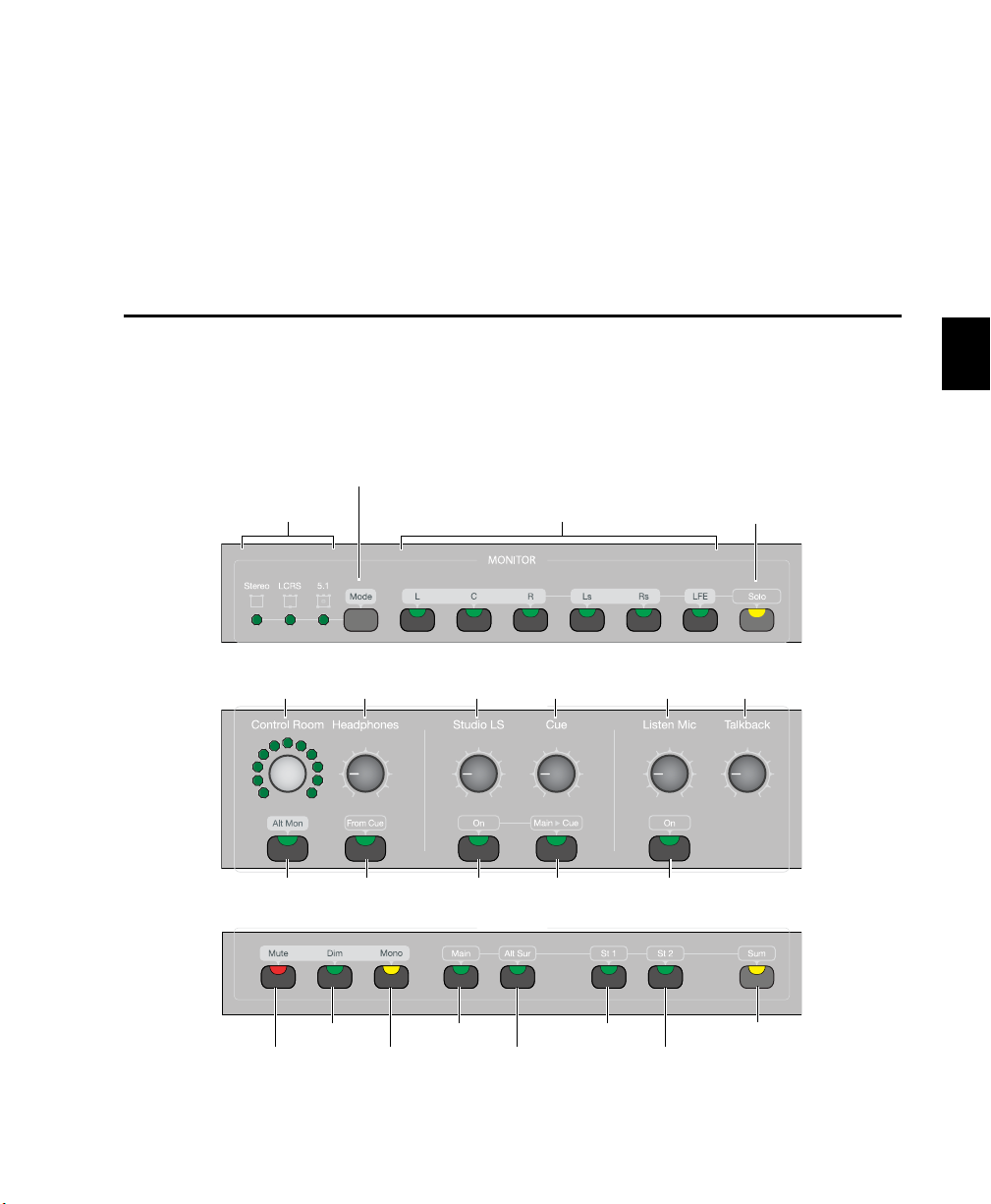
Chapter 7: C|24 Analog Audio Controls
Dim
switch
Mono
switch
Mute
switch
Main
switch
Alt Sur
switch
Stereo 1
switch
Stereo 2
switch
Sum
switch
Output Mode
Preset Indicators
Solo
switch
Control Room Main Output
switches
Output Mode
switch
Control Room
encoder
Headphone
level knob
Solo LS
level knob
Cue
level knob
Listen Mic
level knob
Talkback
level knob
Alt Monitor
switch
From Cue
switch
Studio LS
switch
Main>Cue
switch
Listen Mic
switch
Monitor Section
The Monitor section includes controls for 6-channel control room monitoring, 2-channel studio
loudspeaker and cue system routing, headphone output, and listenback and talkback input.
C|24 Monitor section
Chapter 7: C|24 Analog Audio Controls 61
Page 70

C|24 Monitor section (top)
Output Mode
Preset Indicators
Solo
switch
Control Room Main Output
switches
Output Mode
switch
Output Mode Switch and Indicators
C|24 has three preset monitor modes available
for the Control Room Main Outputs:
•Stereo (L,R)
•LCRS
• 5.1 (L, C, R, Ls, Rs, LFE)
The Output Mode switch cycles through these
three preset modes.
When any of these preset modes is selected,
its indicator lights, and the corresponding Main
Output switches light.
When any of these preset modes is selected
and any of its outputs are disabled, or any additional outputs are enabled, the indicator flashes.
Stereo Mode In Stereo mode, only the Left (L)
and Right (R) output channels of the Control
Room Main Outputs are active, even when
monitoring a surround input source. No summing of the surround channels occurs.
LCRS Mode In LCRS mode, the Left (L), Center
(C), Right (R), and Left Surround (Ls) channels
are active. In this mode, the Left Surround (Ls)
input is routed to both the Left Surround (Ls)
and Right Surround (Rs) outputs.
5.1 Mode In 5.1 mode, all output channels are
active.
Control Room Main Output Switches
The Control Room Main Output switches enable the corresponding output channels. You
can enable any combination of channels at a
time.
An output switch lights to indicate that the
channel is enabled.
The switches are as follows:
•L (Left)
•C (Center)
•R (Right)
• Ls (Left Surround)
• Rs (Right Surround)
• LFE (Low Frequency Effect)
Solo Switch
The Solo switch puts the Main Output switches
in Solo mode, which lets you solo output channels by pressing the corresponding switch. The
Solo switch lights to indicate Solo mode is active.
When you first enter Solo mode, all currently
enabled Main Output switches remain active,
until you press a switch to solo a channel.
C|24 Guide62
Page 71

C|24 Monitor section (middle)
Control Room
encoder
Headphone
level knob
Studio LS
level knob
Cue
level knob
Listen Mic
level knob
Talkback
level knob
Alt Monitor
switch
From Cue
switch
Studio LS
switch
Main>Cue
switch
Listen Mic
switch
Control Room Encoder and LEDs
The Control Room encoder controls the output
volume for the Main and Alt outputs. The encoder LEDs show Gain graphically, and the LCD
displays show Gain values (in dB).
Alt Monitor Switch
The Alt Monitor switch routes the Left and Right
channels to the Alt Outputs, and deactivates the
C, Ls, Rs, and LFE channels. When the Alt Monitor outputs are active, this switch is lit. When
the Main Monitor outputs are active, this switch
is unlit.
Headphone Level Knob
The Headphone level knob controls volume to
the built-in headphone output. The headphone
output is fed by the Left and Right Control
Room Main outputs (channels 1 and 3).
From Cue Switch
The From Cue switch routes the Cue output to
the headphones (post Cue level control) and disables the feed from the Main output. The From
Cue switch lights to indicate that the Cue routing is active.
Studio LS Level Knob and Switch
The Studio LS level knob controls volume to the
Studio LS outputs. The Studio LS switch activates the Studio LS output, and lights to indicate
that the Studio LS is on.
Cue Level Knob and Main to Cue Switch
The Cue level knob controls volume to the Cue
outputs. The Main to Cue switch routes the Left
and Right Control Room outputs to the Cue outputs and disables the feed from the Cue input.
The Main to Cue switch lights to indicate that
the routing is active.
Listen Mic Level Knob and Switch
The Listen Mic level knob controls gain for the
Listen microphone, which feeds the Main output. The Listen Mic switch activates Listenback,
and lights when Listenback is on.
Talkback Level Knob and Switch
The Talkback level knob controls gain for the
Talkback microphone. Talkback signal is
summed with the Cue inputs and also sent to
the Slate output. Talkback is activated by the
Talkback switch in the Transport section.
Chapter 7: C|24 Analog Audio Controls 63
Page 72

C|24 Monitor section (bottom)
Dim
switch
Mono
switch
Mute
switch
Main
switch
Alt Sur
switch
Stereo 1
switch
Stereo 2
switch
Sum
switch
Master Control Room Output
Controls
Mute Switch
The Mute switch mutes all Control Room monitor outputs (Main and Alt), but does not mute
Headphone, Cue, and Studio LS outputs. The
Mute switch lights to indicate that Control
Room outputs are muted.
Dim Switch
The Dim switch applies an adjustable gain reduction to all Control Room monitor outputs
(Main, Alt, and Stereo 1 and 2), but does not affect Headphone, Cue, and LS outputs. The default gain reduction amount is 20 dB. Dim is automatically engaged when Talkback is engaged.
The Dim switch lights to indicate that Control
Room outputs are dimmed.
Mono Switch
The Mono switch sums the Left and Right Control Room outputs (Main, Alt and Stereo 1
and 2), deactivates the C, Ls, Rs, and LFE channels, and lowers monitor output by an adjustable amount. The default gain reduction is 6 dB.
Headphone, Cue, and LS outputs are not affected. The Mono switch lights to indicate that
it is active.
Control Room Input Selectors
Control Room Input selections are mutually exclusive (X-OR) unless the Sum switch is engaged, when they are additive.
Main Switch
The Main switch routes the Main Surround input (Pro Tools In 1-6) to the Control Room outputs. The Main switch lights to indicate that it is
active.
Alt Sur Switch
The Alt Sur switch routes the Alternate Surround
input (Surround In 1-6) to the Control Room
outputs. The Alt Sur switch lights to indicate
that it is active.
Stereo 1 and Stereo 2 Switches
The Stereo 1 and Stereo 2 switches route the External Stereo inputs (Ext St 1 and Ext St 2) to the
Control Room outputs.
These stereo inputs appear in the Left and Right
Control Room output channels only and are excluded from the C, Ls, Rs, and LFE channels.
The Stereo 1 and Stereo 2 switches light to indicate that they are active.
C|24 Guide64
Page 73

Sum Switch
Submixer Output
The Sum switch causes Control Room Inputs to
be additive instead of mutually exclusive
(X-OR). When active, the Sum switch temporarily bypasses any Trim values currently applied to any of the inputs.
The Sum switch latches on, allowing you to select the inputs to be summed. The Sum switch
lights to indicate that it is active.
Monitoring AFL/PFL Signals
(Pro Tools HD Only)
If you are working on a stereo session, you can
monitor soloed tracks in AFL or PFL Solo mode
by routing the AFL/PFL path to one of the C|24
External Stereo inputs and summing that Stereo
input with the C|24 Main input.
To monitor AFL/PFL signals:
1 Connect an unused pair of outputs on your
audio interface to one of the External Stereo inputs on C|24.
2 In the Pro Tools I/O Setup window, select the
pair of audio interface outputs as the AFL/PFL
output path.
3 Select the Main output path to be muted
when you solo a track in AFL or PFL mode.
4 In the Monitor section of C|24, press the Sum
switch so that it is active.
5 Activate the Main input and the External ste-
reo input.
When AFL or PFL Solo mode is selected and a
track is soloed, the Main input is muted and the
AFL/PFL signal is heard on the External Stereo
input.
When the To Monitor switch in the Line Submixer controls is engaged, the stereo output
from the Submixer is routed internally and automatically summed with the Left and Right
channels of the current Control Room Input selection, and are excluded from the C, Ls, Rs, and
LFE channels. Any Trim values applied to the
current input are also applied to the summed
Submixer output.
Trimming Monitor Section Gain
Controls
The gain controls in the Monitor section can be
adjusted to establish channel balance and level
matching between inputs.
Control Room Main Outputs
Each of the Control Room Output channels can
be trimmed individually. Available trim values
range from –30 dB to +10 dB, in 0.5 dB steps.
To trim the level for an individual output channel:
1 Hold the Output Channel switch until the
switch flashes. The channel name and Trim
amount appear in the right side of the LCD displays.
2 Turn the Control Room encoder to adjust the
Trim amount.
3 Press the flashing Output Channel switch to
confirm the change, or press any other switch in
the Monitor section to cancel the change.
4 Repeat the above steps for each output chan-
nel you want to trim.
Chapter 7: C|24 Analog Audio Controls 65
Page 74

Control Room Alt Outputs
Control Room Output Dim Function
The Control Room Alt Outputs can be trimmed
relative to the Main Output to compensate for
differences between speaker systems. The Left
and Right channels of the Alt Output can also be
trimmed relative to each other.
To trim the overall level of the Alt Outputs:
1 Hold the Alt Mon switch until the switch
flashes. The Trim amount appears in the right
side of the LCD displays. Available trim values
range from –30 dB to +6 dB, in 0.5 dB steps.
2 Turn the Control Room encoder to adjust the
Trim amount.
3 Press the flashing Alt Mon switch to confirm
the change, or press any other switch in the
Monitor section to cancel the change.
To trim the level for the Left or Right Alt Output:
1 Press the Alt Mon switch so that the Alt Mon
Output is selected (the switch it lit).
2 Hold the Left or Right Output Channel switch
until the switch flashes. The channel name and
Trim a mount a ppear i n the ri ght si de of t he LCD
displays.
3 Turn the Control Room encoder to adjust the
Trim amount.
4 Press the flashing Output Channel switch to
confirm the change, or press any other switch in
the Monitor section to cancel the change.
The Dim switch applies an adjustable gain reduction to all Control Room monitor outputs.
The amount of Dim gain reduction can be set
while in any monitoring mode.
To set the amount of Dim gain reduction:
1 Hold the Dim switch until the switch flashes.
The Dim amount appears in the right side of the
LCD displays.
2 Turn the Control Room encoder to adjust the
Dim amount.
3 Press the flashing Dim switch to confirm the
change, or press any other switch in the Monitor section to cancel the change.
Control Room Output Mono Function
The Mono switch sums the Left and Right Control Room outputs and lowers monitor output
by an adjustable amount. The amount of Mono
level reduction can be set while in any monitoring mode.
To set the amount of Mono level reduction:
1 Hold the Mute switch until the switch flashes.
The Dim amount appears in the right side of the
LCD displays.
2 Turn the Control Room encoder to adjust the
Mono level reduction amount.
3 Press the flashing Mono switch to confirm the
change, or press any other switch in the Monitor section to cancel the change.
C|24 Guide66
Page 75

Mic/Line/DI Preamplifier Controls
Mic/Line/DI preamplifiers
1-8
Mic/Line/DI preamplifiers
9-16
Input level knob
HPF indicator
Line indicator
Clear Clip
indicator
Mic indicator
Source/HPF
switch
Phantom
Phantom
Power
for
Preamps 1-8
Power
for
Preamps 9-16
The Mic/Line/DI Preamplifier section includes 16 sets of controls for the built-in microphone preamplifiers, and switches to apply phantom power (in two groups of 8 channels).
MIc/Line/DI preamplifiers
Mic Pre Controls
Mic Pre controls
Input Level Knobs (1-8, 9-16)
The Input Level knob adjusts the gain of the corresponding preamplifier.
Clip Indicators
The Clip Indicator is a Red LED that lights when
the corresponding preamplifier receives an input signal that exceeds its capacity.
Source/HPF Switch
The Source/HPF switch cycles through input
sources and toggles high-pass filter in/out status
for the corresponding preamplifier, in this order: Mic, Mic+HPF in, Line, Line+HPF in.
Source and HPF Indicators
The Source Indicators show the active input
source, Mic (yellow) or Line (green), and the
HPF Indicator shows the high-pass filter status
for the corresponding preamplifier.
Phantom Power Switches
Phantom Power switches
The +48V (Phantom Power) switches toggle
phantom power on and off for Mic/Line/DI
preamplifiers 1-8 and 9-16 respectively. The
switches light to indicate that power is applied.
Chapter 7: C|24 Analog Audio Controls 67
Page 76
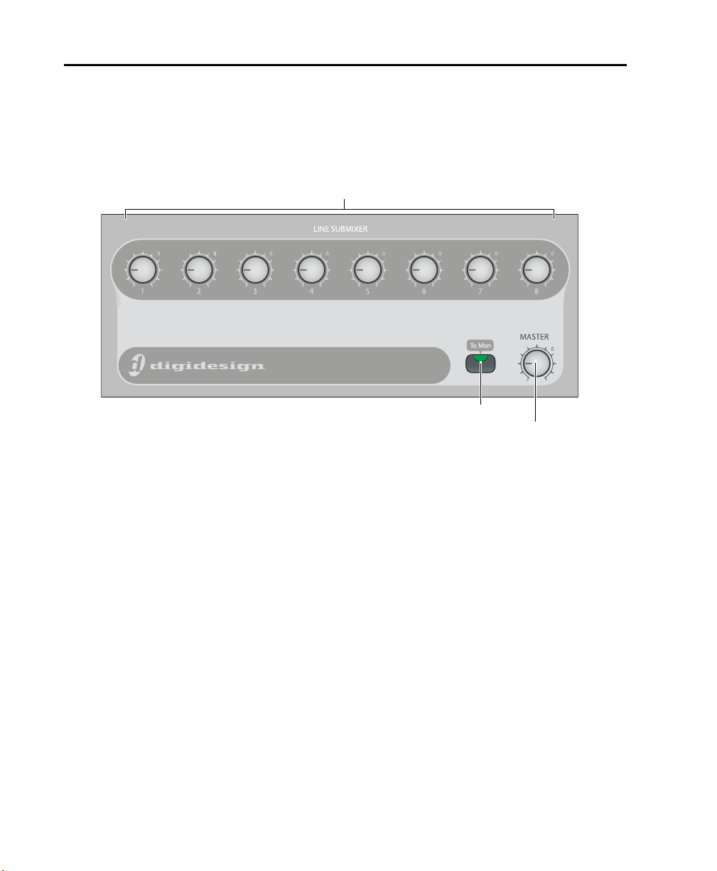
Line Submixer Controls
Input Level knobs
Master Output Level knob
To Monitor switch
The Line Submixer section includes an input level control for each of its 8 inputs and a master output
level control that sets the output levels to the external stereo output or the internal feed to the Monitor section.
Line Submixer
Mixer Input Level Knobs (1-8)
The Input Level knob adjusts the gain of the corresponding Line Submixer input.
To Monitor Switch
The To Monitor switch routes the stereo output
of the Line Submixer to the Monitor section and
automatically sums the signal with the Left and
Right channels of the current Control Room Input selection. Any Trim values applied to the
current input in the Monitor section are also applied to the summed Submixer output.
C|24 Guide68
Master Output Level Knob
The Master Output Level knob controls the volume to the Line Submixer stereo outputs.
Page 77

Part IV: Applications
69
Page 78

70
Page 79

Chapter 8: Operating Views and Modes
C|24 offers two main types of views on its rotary
encoders and LCD displays: Console views and
Channel views.
Console Views Console views display a single
control type across the entire console (for example, Send A on all tracks).
The available Console views are:
• Pan Console view (or “Home” view)
• Sends Console view
Channel Views Channel views display all of the
controls on a single channel (for example, all of
the sends or inserts on a track).
The available Channel views are:
• Pan/Send Channel view
• Expanded Pan view
• Expanded Send view
•Insert Select view
• Parameter view
C|24 offers additional views for working with
Digidesign PRE settings, Pro Tools Mix/Edit
Groups, Window Configurations and Memory
Locations.
C|24 also features powerful Flip mode capability
for transferring different controls to the touchsensitive faders.
Console Views
C|24 Console views let you show pan position or
send assignments and controls across all channels on the control surface.
Pan Console View
“Home” View
Pan Console view is the default or “Home” view
on C|24. In this view, each rotary encoder controls channel pan on its track.
The Pan parameters controlled by the encoder
are selected in the Pan section of the Channel
Bar. Available parameters depend on the track
format and the width of track’s output path.
Mono Track Format Pan on mono tracks is controlled by the track’s encoder.
Stereo Track Format The Left or Right pan controls are focused on the track’s encoder.
Stereo Output Path The track’s encoder controls
panning in the stereo field with the L(C)R pan
parameter.
Multichannel Output Path (Pro Tools HD Only)
The track’s encoder controls panning in the surround field with the L(C)R (or “Front”), FrontRear, Rear, and Center % parameters, as well as
LFE level, depending on the output format.
Chapter 8: Operating Views and Modes 71
Page 80

To display pan controls across the console:
1 Press the Home switch to put C|24 in Pan
Console view.
2 Press a Pan parameter switch in the Pan sec-
tion of the Channel Bar.
3 Press the LCD Display Mode switch repeatedly
until Pan values are shown for each channel on
the LCD displays.
To open/close the Output window for a track:
Hold the Ctrl/Win Modifier key and press the
channel’s encoder switch.
To adjust a track’s pan controls:
1 Press the Home switch to put C|24 in Pan
Console view.
2 Press a Pan parameter switch in the Pan sec-
tion of the Channel Bar.
3 Do one of the following:
• If the track is a mono track, toggle the L/R
switch in the Channel Bar so that it is unlit.
– or –
• If the track is a stereo track, toggle the L/R
switch in the Channel Bar to show the Left
(unlit) or Right (lit) side of the stereo track.
4 Turn the channel’s rotary encoder.
Sends Console View
In Sends Console view, each rotary encoder controls Send volume for a given Send position on
the track.
Send position is selected in the Sends section of
the Channel Bar.
To display a Send position across the console:
1 In the Channel Bar, do one of the following:
• To display a Send A-E, toggle the F-J switch
so that it is unlit, and press a Sends switch
(A/F, B/G, C/H, D/I, or E/J).
– or –
• To display a Send F-J, toggle the F-J switch
so that it is lit, and press a Sends switch
(A/F, B/G, C/H, D/I, or E/J).
2 Press the LCD Display Mode switch repeatedly
until the Send Volume values are shown for
each channel on the LCD displays.
To open/close the Send window for the displayed
Send:
Hold the Ctrl/Win Modifier key and press the
channel’s encoder switch.
To adjust a track’s send levels:
1 In the Channel Bar, press the Sends switch
that corresponds to the name of the Send position you want to adjust.
2 Turn the channel’s rotary encoder.
C|24 Guide72
Page 81

Muting Sends in Sends Console View
To toggle the mute status of a track’s send:
1 In the Channel Bar, press the Sends switch
that corresponds to the name of Send position
you want to mute.
2 In the Switch Functions section, press the
Send Mute switch to assign control of Send
Mute to the encoder switches.
3 Press the channel’s encoder switch.
When the send is muted, the switch is lit and
the LCD display temporarily shows “Mute.”
When the send is not muted, the switch is un-
lit and the LCD display temporarily shows “NoMute.”
When the send is post-fader, the switch is un-
lit and the LCD display temporarily shows
“Post.”
To exit Send Console view:
Press the lit Sends switch in the Channel Bar.
– or –
Enter another view.
Channel Views
C|24 Channel views let you focus all of a track’s
pan controls, send controls, or inserts in the
C|24 LCD displays.
To toggle the mute status of all sends on a track:
1 Press the Insert/Send Bypass switch so that it is
lit.
2 Press the Send switch in the track’s channel
strip.
Setting the Pre-/Post-Fader Status of
Sends in Sends Console View
To toggle the pre-/post-fader status of a track’s
send:
1 In the Channel Bar, press the Sends switch
that corresponds to the name of the Send position you want to change.
2 In the Switch Functions section, press the
Pre/Post switch to assign control of pre-/postfader status to the encoder switches.
3 Press the channel’s encoder switch.
When the send is pre-fader, the switch is lit
and the LCD display temporarily shows “Pre.”
Pan/Send Channel View
In Pan/Send Channel view, Pan and Send controls on the focused channel are displayed horizontally across the LCD displays.
A track is focused in this view by pressing the
Send switch in its channel strip.
To display the Sends on a track:
1 Press the Send switch in the track’s channel
strip. The switch flashes to indicate track focus.
2 If necessary, do one of the following:
• To display Sends A-E, press the F-J switch so
that it is unlit.
– or –
• To display Sends F-J, press the F-J switch so
that it is lit.
The left side of the LCD display shows the
track name in the top row and “Pan/Send” in
the bottom row, followed by “Main Pan” in the
top row and the channel pan value in the bottom row.
Chapter 8: Operating Views and Modes 73
Page 82

For each assigned Send on the track, the LCD
display shows Send position, Send path, “SndPan” on the top row, and Send mute state,
“more” and Send pre/post state on the bottom
row.
For each Send position without an assign-
ment, the LCD display shows “No Send” on the
top row, and “assign” on the bottom row.
Muting Sends in Pan/Send Channel
View
To toggle the mute state of a send on a track:
1 Press the Send switch in the track’s channel
strip.
2 If necessary, scroll the LCD display to show
the Send position you want to mute.
To open the Send window a Send on a track:
1 Press the Send switch in the track’s channel
strip.
2 If necessary, scroll the LCD display to show
the Send position whose window you want to
open.
3 Hold the Ctrl/Win Modifier switch and press
the encoder switch that corresponds to “more.”
To adjust levels for a Send on a track:
1 Press the Send switch in the track’s channel
strip.
2 If necessary, scroll the LCD display to show
the Send position you want to adjust.
3 Turn the encoder that corresponds to the
name of the Send position.
To adjust pan position of a Send on a track:
1 Press the Send switch in the track’s channel
strip.
2 If necessary, scroll the LCD display to show
the Send position you want to adjust.
3 Press the encoder switch that corresponds to
“mute.”
When a Send is muted, the LCD display shows
“MUTE” (all uppercase).
When a Send is not muted, the LCD display
shows “mute” (lowercase).
To mute all sends at the same Send positions on
all tracks:
1 Press the Insert/Send Bypass switch so that it is
lit.
2 Do one of the following:
• Press the Do To All switch.
• Hold the Option/Alt (all) switch.
3 Press the Send switch in a track with a send at
the appropriate Send position.
3 Turn the encoder that corresponds to “Snd-
Pan.”
C|24 Guide74
Page 83

Setting the Pre-/Post-Fader Status of
Sends in Pan/Send Channel View
To toggle the pre-/post-fader state of any of the
sends on a track:
1 Press the Send switch in the track’s channel
strip.
2 If necessary, scroll the LCD display to show
the Send position you want to change.
3 Press the encoder switch that corresponds to
“SndPan” to toggle the pre-/post-fader state.
Expanded Pan View
You can display all the Pan controls for a track
in Expanded Pan view.
To display the Pan controls for a track in Expanded
Pan view:
Double-press the Send switch in the track’s
channel strip.
– or –
1 Press the Send switch in the track’s channel
strip.
To display the Output window for a track:
1 Press the Send switch in the track’s channel
strip.
2 Hold the Ctrl/Win Modifier switch and press
the encoder switch that corresponds to “Main
Pan.”
To exit Pan/Send Channel view, do any of the
following:
Press the flashing Sends switch in the channel
strip.
Press the encoder switch that corresponds to
“Pan/Send.”
Enter another view.
2 Press the encoder switch that corresponds to
“Main Pan.”
The left side of the LCD displays the track
name in the top row and “Main Output” in the
bottom row, followed by track Mute, Solo, Automation Safe, and Volume displays.
The LCD display also shows pan parameters as
follows:
Stereo Output Path Tracks assigned to a stereo
output path show Left-Right pan. Stereo tracks
assigned to a stereo output path also show
Left/Right Pan Link and Front Inverse Link controls.
Multichannel Output Path (Pro Tools HD Only)
Tracks assigned to a multichannel output path
can show Front Pan, Rear Pan, Front/Rear Pan,
Front Divergence, Rear Divergence, Front/Rear
Divergence, Center %, and LFE level, depending
on the output format. Stereo tracks assigned to a
multichannel output path also show Pan Link
controls (Left/Right Link, Front Inverse Link,
Rear Inverse Link, and Front/Rear Inverse Link).
Chapter 8: Operating Views and Modes 75
Page 84

To adjust a track’s volume in Expanded Pan view:
1 Press the Send switch in the track’s channel
strip.
2 Press the encoder switch that corresponds to
“Main Pan.”
3 Turn the encoder that corresponds to “Vol-
ume.”
To adjust a track’s pan controls in Expanded Pan
view:
1 Press the Send switch in the track’s channel
strip.
2 Press the encoder switch that corresponds to
“Main Pan.”
3 Do one of the following:
• If the track is a mono track, toggle the L/R
switch in the Channel Bar so that it is unlit.
– or –
• If the track is a stereo track, toggle the L/R
switch in the Channel Bar to show the Left
(unlit) or Right (lit) side of the stereo track.
To toggle track panner linking in Expanded Pan
view:
1 Press the Send switch in the track’s channel
strip.
2 Press the encoder switch that corresponds to
“Main Pan.”
3 Press the encoder switch that corresponds to
any of the following:
• Link (Left/Right panner link)
• Front (Front Inverse link)
• Rear (Rear Inverse link)
• FrRear (Front/Rear Inverse link)
When a panner linking option is On or Inverted, the corresponding encoder switch is lit.
To exit Expanded Pan view, do any of the
following:
Press the encoder switch that corresponds to
“Main Output.”
Press the flashing Send switch in the track’s
channel strip.
4 Turn the rotary encoders for the available pan
or divergence parameters in the LCD displays.
To toggle the mute, solo, or automation safe
status of a track in Expanded Pan view:
1 Press the Send switch in the track’s channel
strip.
2 Press the encoder switch that corresponds to
“Main Pan.”
3 Press the encoder switch that corresponds to
“Mute,” “Solo,” or “Safe” to toggle the function
On or Off.
When track Mute, Solo, or Automation Safe is
On, the corresponding encoder switch is lit.
C|24 Guide76
Enter another view.
Expanded Send View
You can display all the controls for an individual Send in Expanded Send view.
To display the controls for a Send in Expanded
Send view:
1 Press the Send switch in the track’s channel
strip.
2 If necessary, do one of the following:
• To display Sends A-E, press the F-J switch so
that it is unlit.
– or –
• To display Sends F-J, press the F-J switch so
that it is lit.
Page 85

3 For the Send you want to display, press the en-
coder switch that corresponds to “more.”
The LCD displays show the track name in the
top row and the Send position and Send path in
the bottom row, followed by Send Mute, track
Solo, Send Automation Safe, Send Pre/Post, Follows Main Pan, and Send Volume displays.
The LCD displays also show pan parameters as
follows:
Stereo Output Path Sends assigned to a stereo
Send path show Left-Right pan. Stereo Sends assigned to a stereo Send path also Left/Right Pan
Link and Front Inverse Link controls.
To adjust a Send’s pan controls in Expanded Send
view:
1 Press the Send switch in the track’s channel
strip.
2 For the Send you want to display, press the en-
coder switch that corresponds to “more.”
3 Do one of the following:
• If the Send is a mono Send, toggle the L/R
switch in the Channel Bar so that it is unlit.
– or –
• If the Send is a stereo Send, toggle the L/R
switch in the Channel Bar to show the Left
(unlit) or Right (lit) side of the stereo track.
Multichannel Output Path (Pro Tools HD Only)
Sends assigned to a multichannel output path
can show Front Pan, Rear Pan, Front/Rear Pan,
Front Divergence, Rear Divergence, Front/Rear
Divergence, Center %, and LFE level, depending
on the output format. Stereo tracks assigned to a
multichannel output path also show Pan Link
controls (Left/Right Link, Front Inverse Link,
Rear Inverse Link, and Front/Rear Inverse Link).
To adjust a Send’s volume in Expanded Send view:
1 Press the Send switch in the track’s channel
strip.
2 For the Send you want to display, press the en-
coder switch that corresponds to “more.”
3 Turn the encoder that corresponds to “Vol-
ume.”
4 Turn the rotary encoders for the available pan
or divergence parameters in the LCD displays.
To toggle the Send mute, track solo, or Send
automation safe state in Expanded Send view:
1 Press the Send switch in the track’s channel
strip.
2 For the Send you want to display, press the en-
coder switch that corresponds to “more.”
3 Press the encoder switch that corresponds to
“Mute,” “Solo,” or “Safe” to toggle the function
On or Off.
When Send Mute, track Solo or Send Automation Safe is On, the corresponding encoder
switch is lit.
To toggle the pre-/post-fader state of a Send in
Expanded Send view:
1 Press the Send switch in the track’s channel
strip.
2 For the Send you want to display, press the en-
coder switch that corresponds to “more.”
3 Press the encoder switch that corresponds to
“Pre/Pst” to toggle the pre-/post-fader state.
Chapter 8: Operating Views and Modes 77
Page 86

To link a Send’s Pan controls to the Main Pan
controls of a track (“Follows Main Pan”):
1 Press the Send switch in the track’s channel
strip.
2 For the Send you want to display, press the en-
coder switch that corresponds to “more.”
3 Press the encoder switch that corresponds to
“FMP” to toggle Follows Main Pan On and Off.
When Follows Main Pan is On, the corre-
sponding encoder switch is lit.
Insert Select View
In Insert Select view, insert controls on the focused channel are displayed horizontally across
the LCD displays.
A track is focused in this view by pressing the Insert switch in its channel strip.
To display the Inserts on a track:
Press the Insert switch in the track’s channel
strip. The switch flashes to indicate track focus.
To toggle Send panner linking in Expanded Send
view:
1 Press the Send switch in the track’s channel
strip.
2 For the Send you want to display, press the en-
coder switch that corresponds to “more.”
3 Press the encoder switch that corresponds to
any of the following:
• Link (Left/Right panner link)
• Front (Front Inverse link)
• Rear (Rear Inverse link)
• FrRear (Front/Rear Inverse link)
When a panner linking option is On or Inverted, the corresponding encoder switch is lit.
To exit Expanded Send view, do any of the
following:
Press the encoder switch that corresponds to
the name of Send position.
Press the flashing Send switch in the track’s
channel strip.
Enter another view.
The left side of the LCD display shows the track
name in the top row and “Inserts” in the bottom
row.
For each assigned Insert on the track, the LCD
displays show Insert position and Insert name
on the top row, “more” and Insert bypass state
on the bottom row.
For each Insert position without an assignment,
the LCD displays show “No Insert” on the top
row, and “assign” on the bottom row.
To cycle through the Inserts on a track:
Double-press the Insert switch on the track’s
channel strip.
Focusing Plug-Ins on C|24
A focused plug-in is indicated on-screen by a
colored outline around the plug-in button and
around the plug-in window header.
In Insert Select view, a focused plug-in is indicated on C|24 by an asterisk (“*”) below the Insert position in the LCD displays, a flashing
plug-in name and a flashing encoder switch.
You can display the parameters of a focused
plug-in in Parameter view. See “Parameter View”
on page 80.
C|24 Guide78
Page 87

To focus a plug-in:
1 Press the Insert switch in the track’s channel
strip.
To open multiple plug-in windows:
Hold the Shift (add) Modifier switch while
opening each new plug-in window.
2 Press the encoder switch to the left of the
“more” encoder switch for the plug-in. An asterisk (“*”) appears below the Insert position to indicate that the plug-in is focused.
Opening Plug-in Windows
You can focus a plug-in on C|24 with or without
displaying its window on-screen.
To set C|24 to automatically open windows of
focused plug-ins:
1 Press the Soft Keys switch.
2 Press the encoder switch that corresponds to
“ChanWn” so that its value is “Yes.”
3 Press the lit Soft Keys switch.
With this preference set to “Yes,” when you assign or focus a plug-in, the plug-in window will
open automatically on-screen.
To focus a plug-in on C|24 and open its window:
1 Press the Insert switch of the track whose plug-
in you want to focus.
2 Press the encoder switch that corresponds to
the Insert position for the plug-in.
The focused plug-in is indicated on C|24 by an
asterisk below the Insert position.
To open or close a plug-in window on-screen for an
Insert without focusing it on C|24:
1 Press the Insert switch in the track’s channel
strip.
To close all open plug-in windows:
Hold the Opt/Alt (all) Modifier switch and
press the Plug-in switch in the Windows section.
Bypassing Plug-ins
When a plug-in is bypassed, the LCD display
shows “BYPASS” (all uppercase) and the plug-in
name changes to all uppercase.
When an plug-in is not bypassed, the LCD display shows “bypass” (lowercase) and the plug-in
name changes to all lowercase.
To toggle the bypass state of a plug-in:
1 Press the Insert switch in the track’s channel
strip.
2 Press the encoder switch that corresponds to
“bypass.”
To toggle the bypass state of all plug-ins on a
track:
1 Press the Insert switch in the track’s channel
strip.
2 Press the Mstr Bypass switch in the Inserts sec-
tion of the Channel Bar.
– or –
1 Press the Insert/Send Bypass switch so that it is
lit.
2 Press the Insert switch in the track’s channel
strip.
2 Hold the Ctrl/Win Modifier switch and press
the encoder switch that corresponds to “more”
for the plug-in.
Chapter 8: Operating Views and Modes 79
Page 88

To toggle the bypass state of all plug-ins at the
same insert positions on all tracks:
1 Press the Insert/Send Bypass switch so that it is
lit.
2 Do one of the following:
• Press the Do To All switch.
• Hold the Option/Alt (all) switch.
3 Press the Insert switch in a track with an insert
at the appropriate insert position.
All plug-ins at the same insert positions will be
bypassed on all tracks.
Deactivating Inserts on C|24
To deactivate an Insert on a track:
1 Press the Insert switch in the track’s channel
strip.
In Parameter view, the LCD displays show the
parameter names in the top row and the parameter values in the bottom row. The encoders and
the encoder switches control the corresponding
parameters.
If there are more parameters than can be displayed at once on the LCD displays, the Channel Bar Scroll switch flashes.
When you change a plug-in parameter, the
Compare switch in the Inserts section of the
Channel Bar lights.
To display the controls for a plug-in:
1 Press the Insert switch in the track’s channel
strip.
2 For the plug-in you want to display, press the
encoder switch that corresponds to “more.”
2 Hold the Command/Ctrl+Ctrl/Win Modifier
switches and press the encoder switch that corresponds to “more” (for plug-ins) or the insert
name (for I/O inserts).
When an Insert is inactive, the LCD display
shows “inactv” (all lowercase) and an “@” sign
appears in front of the plug-in name.
To activate an inactive Insert:
Hold the Command/Ctrl+Ctrl/Win Modifier
switches and press the encoder switch that corresponds to “inactv.”
Parameter View
You can display all the controls for an individual plug-in in Parameter view. (Hardware inserts
do not have a Parameter view.)
C|24 Guide80
To cycle display of all the plug-ins on a track:
Double-press the Insert switch in the track’s
channel strip.
To display the currently focused plug-in:
1 Press the Insert switch in the track’s channel
strip.
2 Press the Insert/Param switch in the Inserts
section of the Channel Bar.
To temporarily show the track name, Insert
position and name of the currently focused plug-in:
Hold the LCD Display switch.
– or –
Hold the Insert switch on a channel.
To toggle the bypass state of the currently
displayed plug-in:
In Parameter view, press the Mastr Bypass
switch in the Inserts section of the Channel Bar.
Page 89

To toggle the automation safe status of the
currently focused plug-in:
Press the Safe switch in the Inserts Section of
the Channel Bar.
To compare plug-in parameter changes with the
currently loaded plug-in setting:
Press the lit Compare switch.
To return to Insert Select view:
Press the flashing Insert/Param switch.
– or –
Press the Insert switch in a track’s channel
strip.
Viewing EQ and Dynamics Plug-ins
To toggle the bypass state of all Dyn or EQ plug-ins
at the same insert positions on all tracks:
1 Press the Dyn/EQ Bypass switch so that it is lit.
2 Do one of the following:
• Press the Do To All switch.
• Hold the Option/Alt (all) switch.
3 Press the Dyn or EQ switch on a track that has
plug-ins of the corresponding type.
All plug-ins of the same type and at the same insert positions will be bypassed on all tracks.
Setting Up Multi-mono Plug-ins
When using a multi-mono plug-in on a multichannel track, you can link channels of the
plug-in from Parameter view.
To display the controls for the first (or most
recently focused) EQ or Dynamics plug-in on a
track:
Press the EQ or Dynamics switch on the track.
To cycle display of the EQ or Dynamics plug-ins on
a track:
1 Press the EQ or Dynamics switch in the track’s
channel strip to display the first (or most recently focused) plug-in of the corresponding
type.
2 Double-press the EQ or Dynamics switch to
display the next plug-in of the corresponding
type.
Bypassing EQ and Dynamics Plug-ins
To toggle the bypass state of all Dyn or EQ plug-ins
on a track:
1 Press the Dyn/EQ Bypass switch so that it is lit.
2 Press the Dyn or EQ switch on the track.
To display the multi-mono plug-in Setup page:
1 Press the Insert switch in the track’s channel
strip.
2 For the plug-in you want to display, press the
encoder switch that corresponds to “more.”
3 Hold the Insert/Param switch in the Inserts
section of the Channel Bar until the Setup page
appears in the LCD displays.
The LCD displays show the track name in the
top row and “Link,” “Target,” “Group,” and
“Bypass” in the bottom row.
To unlink or relink channels on a multi-mono
plug-in:
From the multi-mono plug-in setup page:,
press the encoder switch that corresponds to
“Link.”
Chapter 8: Operating Views and Modes 81
Page 90

To target controls for a specific channel on a multimono plug-in:
1 From the multi-mono plug-in setup page,
press the encoder switch that corresponds to
“Target.”
2 Press the encoder switch that corresponds to
the channel you want to target, which can include Left, Center, Right, Left Surround, Right
Surround, or LFE.
Mic Pre View
If you have a Digidesign PRE in your system, Mic
Pre views let you control the PRE from C|24.
Mic Pre Console View
To display PRE gain values across all channels:
Press the Mic Pre switch.
To link the controls of specific channels on a multimono plug-in:
1 From the multi-mono plug-in setup page,
press the encoder switch that corresponds to
“Group.”
2 Press the encoder switches that correspond to
the channels of the plug-in you want to group,
which can include Left, Center, Right, Left Surround, Right Surround, and LFE.
To bypass channels on a multi-mono plug-in:
1 From the multi-mono plug-in setup page,
press the encoder switch that corresponds to
“Bypass.”
2 Press the encoder switches that correspond to
the channels of the plug-in you want to bypass,
which can include Left, Center, Right, Left Surround, Right Surround, and LFE.
To exit the multi-mono plug-in Setup page:
Press the flashing Insert/Param switch.
To exit Parameter view, do any of the following:
Press the flashing Insert switch in the track’s
channel strip.
Press the Insert/Param switch in the Inserts
section of the Channel Bar.
The track name is displayed in the top row, and
the Gain value (in dB) is displayed in the bottom
row, prefaced by one of the following:
• MGn: Microphone gain
• LGn: Line In gain
•IGn: Direct Input gain
Gain is controlled by the encoder.
To open the Mic Pre window for a track:
Hold the Ctrl/Win Modifier switch and press
the encoder switch for the track.
To exit Mic Pre view, do any of the following:
Press the lit Mic Pre switch.
Enter another view.
Expanded Mic Pre View
You can display all of the PRE controls for a
channel in Expanded Mic Pre view.
To display the PRE controls for a channel in
Expanded Mic Pre view:
1 Press the Mic Pre switch.
2 Press the encoder switch that corresponds to
the channel you want to display.
Enter another view.
C|24 Guide82
Page 91

In Expanded Mic Pre view, the following controls are shown in the LCD displays:
• Gain: controlled by the encoder
• Source: chosen with the encoder
• Impedance: chosen with the encoder (for
Mic/Line source only)
• Pad: toggled with the encoder switch
• Polarity: toggled with the encoder switch
• Phantom Power: toggled with the encoder
switch
• High-Pass Filter: toggled with the encoder
switch
• Insert: toggled with the encoder switch
Creating Groups
To create a group:
1 Select the tracks you want to include in the
group.
2 Press the Create switch in the Groups section.
Current groups are shown in the LCD displays,
with the group ID in the top row, and the group
name in the bottom row.
3 Select the Group ID for the new group by
pressing the corresponding encoder switch.
4 Enter a name, select a type, and set attributes
for the group.
To open the Mic Pre window for the track:
Hold the Ctrl/Win Modifier switch and press
the encoder switch that corresponds to “Mic
Pre.”
To exit Expanded Mic Pre view, do any of the
following:
Press the lit Mic Pre switch in the view section.
Press the encoder switch that corresponds to
“Mic Pre.”
Enter another view.
Groups View
C|24 lets you show Pro Tools Mix/Edit groups in
the LCD displays, and create, enable, modify
and delete groups from the control surface.
Displaying Group Membership of Tracks
You can set C|24 to show the Group ID of tracks
along with their track names in the LCD displays. See the description of the Track Display
option in “Console Preferences” on page 47.
5 Press Enter to confirm the new group.
6 When you are finished creating groups, press
the flashing Create switch.
Enabling and Suspending Groups
To enable or suspend a group:
1 Press the Enable switch in the Groups section.
Current groups are shown in the LCD displays,
with the group ID in the top row, and the group
name in the bottom row.
Enabled groups are indicated by lit encoder
switches.
Suspended groups are indicated by flashing
encoder switches.
2 Press encoder switches to enable or suspend
the corresponding groups.
3 When you are finished enabling groups, press
the flashing Enable switch.
Chapter 8: Operating Views and Modes 83
Page 92

Modifying Groups
To modify a group:
1 Press the Modify switch in the Groups section.
Current groups are shown in the LCD displays,
with the group ID in the top row, and the group
name in the bottom row.
2 Select the group you want to modify by press-
ing the corresponding encoder switch. Group
members are indicated by lit Channel Select
switches. Track names are shown in the top row
of LCD displays.
3 Press Channel Select switches to add or re-
move tracks from the group.
4 Press the Modify switch to confirm the
changes.
To suspend all groups:
Press the Suspend switch in the Groups sec-
tion. The Suspend Groups switch follows latching behavior, and flashes to indicate groups are
suspended.
To exit Suspend Groups mode:
Press the flashing Suspend Groups switch.
Window Configuration View
C|24 lets you open and close the Window Configuration list and lets you display and select
Window Configurations from the control surface. Window Configuration names are shown
in the bottom row of the LCD displays.
Deleting Groups
Deleting groups cannot be undone.
To delete a group:
1 Press the Delete switch in the Groups section.
Current groups are shown in the LCD displays,
with the group ID in the top row, and the group
name in the bottom row.
2 Press lit encoder switches to delete the corre-
sponding groups.
3 Do one of the following:
• Press the Enter switch to confirm the deletion.
– or –
• Press the Esc/Cancel switch to cancel and
leave groups unchanged.
4 When you are finished deleting groups, press
the flashing Delete switch.
If there are more Window Configurations than
can be shown at once on the LCD displays. the
Channel Bar Scroll switch flashes.
To toggle display of the Window Configurations list
on-screen:
Press the Window Configuration (Win Cfg)
switch.
To toggle display of Window Configurations in the
LCD displays:
In Home view, hold the Command/Ctrl Mod-
ifier switch and press the Window Configuration (Win Cfg) switch.
To recall a Window Configuration:
In Window Configuration view, press the en-
coder switch that corresponds to the Window
Configuration name in the LCD display.
C|24 Guide84
Page 93

To edit a Window Configuration:
In Window Configuration view, hold the
Ctrl/Win modifier switch and press the encoder
switch that corresponds to the Window Configuration name in the LCD display.
To create a new Window Configuration:
In Window Configuration view, hold the
Ctrl/Win modifier switch and press an encoder
switch that corresponds to a blank area of the
LCD display.
To exit WIndow Configuration view:
Hold the Command/Ctrl Modifier switch and
press the flashing Window Configuration
switch.
Memory Location View
C|24 lets you open and close the Memory Locations window and display and select Memory
Locations from the control surface.
In Memory Location view, Memory Location
names are shown in the bottom row of the LCD
displays.
To recall a Memory Location:
In Memory Location view, press the encoder
switch that corresponds to the location name in
the LCD display.
To edit a Memory Location:
In Memory Location view, hold the Ctrl/Win
modifier switch and press the encoder switch
that corresponds to the location name in the
LCD display.
To create a new Memory Location, do one of the
following:
In Memory Location view, hold the Ctrl/Win
modifier swtich and press an encoder switch
that corresponds to a blank area of the LCD display.
– or –
In any view, press the Enter switch in the
File/Utility section.
To exit Memory Location view:
Hold the Command/Ctrl Modifier switch and
press the flashing Memory Location switch.
If there are more Memory Locations than can be
shown at once on the LCD displays. the Channel Bar Scroll switch flashes.
To toggle display of the Memory Locations window
on-screen:
Press the Memory Location (Mem Loc) switch.
To toggle display of Memory Locations in the LCD
displays:
In Home view, hold the Command/Ctrl Mod-
ifier switch and press the Memory Location
switch.
Chapter 8: Operating Views and Modes 85
Page 94

Fader Display Modes
Normal Mode
In Normal mode, Pro Tools tracks are displayed
on C|24 in a standard console format. In this
mode, each channel strip corresponds to a track
in the session, and most of the channel strip
controls correspond directly to on-screen controls or views in Pro Tools:
• Faders control channel volume.
• LCD displays show track name, and track
volume when fader is touched.
• Rotary encoders control channel pan.
• In Insert views, rotary encoders and encoder switches control inserts and plug-in
parameters.
• In Send views, rotary encoders and encoder
switches control Send pan, mute, and prepost fader operation.
Master Faders Mode
The Masters switch cycles temporary display of
Master Fader tracks and VCA Master tracks
(Pro Tools HD only) on the right side of the C|24
faders. The Masters switch flashes to indicate
display of Master Faders or VCA Master tracks.
Home/Pan Flip Mode
When C|24 is in Pan Console or “Home” view,
Flip mode transfers control assignments as follows:
• Faders control channel pan.
• Rotary encoders control channel volume.
When an Instrument track is in MIDI mode, Flip
mode transfers control assignments as follows:
• Faders control MIDI pan.
• Rotary encoders control MIDI volume.
Send Flip Mode
Flip mode transfers Send control assignments as
follows:
Sends Console View
• Faders control Send level.
• Rotary encoders control Send pan.
• For stereo Sends, control of Left and Right
channel pan is selected with the L/R switch
in the Pan section.
• For Sends to multichannel output paths,
control of Send Pan parameters is selected
in the Pan section of the Channel Bar
• Encoder switches control Send Mute or
Send Pre/Post status, depending on the
Switch Functions setting
Flip Modes
Flip mode temporarily exchanges control
assignments between the rotary encoders and
the corresponding channel faders, so you can
use the touch-sensitive faders to edit and
automate pan, send and plug-in parameter
values.
The effect of Flip mode depends on the current
view.
C|24 Guide86
Pan/Sends Channel View
• Fader under “Main Pan” controls channel
pan.
• Fader under Send position name controls
Send level.
• Fader under “SndPan” controls Send pan.
• Encoder switch under “Mute” controls
Send mute.
•Encoder switch under “SndPan” controls
Send pre/post operation.
Page 95

Expanded Pan/Expanded Send View
• Faders control Send parameters.
• Rotary encoders are disabled.
• Encoder switches toggle/cycle through
stepped parameters.
Plug-in Flip Mode
When C|24 is in Parameter view, Flip mode
transfers the control assignments as follows:
• Faders control plug-in parameters.
• Rotary encoders are disabled.
• Encoder switches toggle/cycle through
stepped parameters.
Assign Mode
You can assign Inputs, Outputs, Inserts, or Sends
from C|24 using Assign mode.
When in Assign mode, an arrow (“>”) appears to
the left of pathnames or plug-in names in the
LCD displays to indicate the current assignment. The arrow disappears to when an unconfirmed change is displayed.
When navigating in Assign mode, you can move
up a level by holding the Command/Ctrl switch
and pressing the encoder switch for the control
that you are assigning.
Mic Pre Flip Mode
Flip mode transfers PRE control assignments to
the faders and disables the encoders, as follows:
Mic Pre Console View
• Faders control PRE gain.
Mic Pre Expanded View
• Fader under “Gain” controls PRE gain.
• Fader under “Source” toggles the PRE input
source.
• Fader under “Impedance” controls the Impedance setting.
See “Assigning Pro Tools Paths” on page 91.
You can enter Assign mode while in Flip
mode. In Flip mode, move the faders (instead of the encoders) to scroll through lists
in Assign mode.
Chapter 8: Operating Views and Modes 87
Page 96

C|24 Guide88
Page 97

Chapter 9: Working with C|24
This chapter covers representative Pro Tools
tasks that can be accomplished with C|24. For
complete information on C|24 controls for
Pro Tools, see Chapter 6, “C|24 Pro Tools Controls.” For complete information on the views
and modes available on C|24, see Chapter 8,
“Operating Views and Modes.”
Working with Sessions and Tracks
Saving a Session
To save the current session:
1 Press the Save switch. The switch flashes,
prompting confirmation of the Save command.
2 Do one of the following:
• To confirm the Save command, press the
Save switch again.
– or –
• To cancel the Save command, press the
Esc/Cancel switch.
Creating New Tracks
When you are creating new tracks in Pro Tools,
you can navigate the New Tracks dialog using
the Arrow switches on C}24.
To increase or decrease the number of tracks:
Press the Up or Down Arrow switch.
To scroll through the track types:
Hold the Command/Ctrl Modifier switch and
press the Up or Down Arrow switch.
To scroll through the track formats:
Hold the Command/Ctrl Modifier switch and
press the Previous (Left) or Next (Right) Arrow
switch.
To toggle the timebases:
Hold the Command/Ctrl+Opt/Alt (all) Modi-
fier switches and press the Up or Down Arrow
switches.
Chapter 9: Working with C|24 89
Page 98

Naming Tracks or Adding Track
Comments
Resetting Controls to Their
Default Values
When you are naming tracks or adding track
comments, you can open and navigate the
Name Track dialog from C|24.
To open the Track Name/Comments dialog for a
track:
Double-press the channel’s Select switch.
To move the cursor while naming a track, do any of
the following:
Press the Previous (Left) or Next (Right) Arrow
switch to move the cursor backward or forward
through the field.
Press the Up or Down Arrow switch to move
the cursor to the beginning or end of the field.
Hold the Command/Ctrl Modifier switch and
press the Up (or Left) or Down (or Right) Arrow
switch to move to the previous or next track
name field.
To reset a channel’s track volume to 0 dB:
Press Default + the channel Select switch.
– or –
Hold Option/Alt (all) and touch the channel
fader.
To reset a channel’s pan control to 0 (center)
Press Default + the encoder switch.
To reset a send’s level to 0 dB:
Press Default + the encoder switch under
“more.” This sets the send level to 0 dB, regardless of the Send default setting in Pro Tools Operation preferences.
To reset a channel’s mic pre gain to 0 dB:
Press Default + the encoder switch under the
gain display.
To set a plug-in’s parameters to their default
values:
Press Default + the Compare switch.
You can also hold Option/Alt (all) and
press the corresponding switch to reset
parameters to their default values.
C|24 Guide90
Page 99

Applying Actions to Multiple
Tracks
To apply actions to multiple tracks:
1 Do one of the following:
• Press the Do To All or the Do To Selected
switch to apply the action to one control.
– or –
• Double-press the Do To All or the Do To Selected switch to latch the corresponding action and apply it to multiple controls.
Assigning Pro Tools Paths
You can assign track inputs, outputs, sends, and
inserts from C|24.
Assigning Inputs and Outputs
To assign inputs or Outputs:
1 From Pan Console (or “Home” view), press the
Assign switch in the Assign section of the Channel Bar.
2 Press any of the following switches to apply
the corresponding action to all tracks or all selected tracks in the current session:
• Channel Mute switch
• Channel Solo switch
• Channel Solo Safe: Command/Ctrl Modifier switch + Solo switch
• Global Automation Mode switches
• Channel Automation Mode switches
• Channel Select switch
• Record Enable switch
• Record Safe: Command/Ctrl Modifier
switch + Record Enable switch
• Input Monitor Mode switch (Pro Tools HD
Only)
3 You can also carry out any of the following
tasks across all tracks or all selected tracks in the
session:
• Assigning Inputs, Outputs, Inserts and
Sends
• Deactivating Inserts
• Resetting controls with the Default switch
• Changing panner linkage
2 Press the Input switch or Output switch in the
Assign section of the Channel Bar.
3 On each channel where you want to make an
assignment, turn the rotary encoder (or in Flip
mode, move the fader) to scroll through the list
of Inputs or Outputs.
4 Do one of the following:
• To confirm each assignment separately,
press the flashing encoder switch on each
channel.
• To confirm all assignments at once, press
the flashing Assign switch in the Assign
section of the Channel Bar.
• To cancel any unconfirmed assignments
and leave Assign mode, press the flashing
Escape/Cancel switch.
4 When you are finished, if Do To all or Do To
Selected are latched on, press the flashing Do To
All or Do To Selected switch to exit the corresponding mode.
Chapter 9: Working with C|24 91
Page 100

Assigning Sends
To assign a Send from Console view:
1 Press a Send switch in the Sends section of the
Channel Bar.
2 Press the Assign switch in the Assign section of
the Channel Bar.
3 Unassigned Send positions show the top level
menu for assigning Send paths: “bus” or ‘interfc” (Interface).
4 Navigate the Send paths menu by doing the
following:
• Turn the encoder to scroll through menu
items.
• To go down a menu level, press the encoder
switch that corresponds to the Send path.
• To go up a level, hold the Command/Ctrl
Modifier switch and press the encoder
switch that corresponds to the Send path.
5 On each channel where you want to make an
assignment, turn the rotary encoder to scroll
through the list of Send paths.
6 Do one of the following:
• To confirm each assignment separately,
press the flashing encoder switch on each
channel.
• To confirm all assignments at once, press
the flashing Assign switch in the Assign
section of the Channel Bar.
• To cancel any unconfirmed assignments
and leave Assign mode, press the flashing
Escape/Cancel switch.
To assign a Send from Channel view:
1 Press the Send switch in the track’s channel
strip. The Send positions for the track are shown
in the LCD displays.
2 Press the Assign switch in the Assign section of
the Channel Bar.
3 Unassigned Send positions show the top level
menu for assigning Send paths: “bus” or ‘interfc” (Interface).
4 Navigate the Sends menu by doing the follow-
ing:
• Turn the encoder (or in Flip mode, move
the fader) to scroll through menu items.
• To go down a menu level, press the encoder
switch that corresponds to “select.”
• To go up a level, press the encoder switch
that corresponds to “back.”
5 On each channel where you want to make an
assignment, turn the rotary encoder to scroll
through the list of Send paths.
6 Do one of the following:
• To confirm each assignment separately,
press the flashing encoder switch on each
channel.
• To confirm all assignments at once, press
the flashing Assign switch in the Assign
section of the Channel Bar.
• To cancel any unconfirmed assignments
and leave Assign mode, press the flashing
Escape/Cancel switch.
C|24 Guide92
 Loading...