

Page 1
Installation Manual
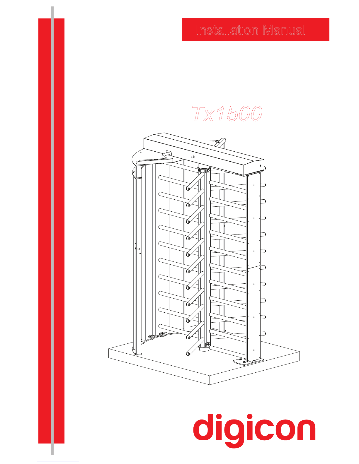
Turnstile
Tx1500
Page 2

Page 3

Copyright– Digicon S.A.
Controle Eletrônico para Mecânica – 2013
All rights reserved. No part of this publication may be reproduced,
transmitted, transcribed, stored in a retrieval system, translated into any
language or computer language in any electronic, magnetic, optical, chemical,
manual way, or otherwise, without the express written permission from
Digicon S.A.
Códe: 069.31.211
V
ersion: 01
This manual was elaborated by:
Digicon S.A. Electronic Control for Mechanics Documentation Sector - EDS
Page 4

Contents
1. IMPORTANT INSTRUCTIONS ................................................................
2. ORIENTATIONS .................................................................................
3. INTRODUCTION ................................................................................
4. INSTALLING Tx1500 ..........................................................................
5. CAPTIONS ........................................................................................
6. POWER SUPPLY .................................................................................
7. CONTROL BOARD ..............................................................................
7.1.INPUTS ..........................................................................................
7.2.OUTPUTS ........................................................................................
7.3.CONFIGURATION OF CONTROL BOARD - SWITCHES DS1 AND Ds2 .........
7.4.EXAMPLES OF SOME CONFIGURATIONS ..............................................
7.5. SERIAL COMMUNICATION ................................................................
8. DIMENSIONS ....................................................................................
9. WARRANTY AND TECHNICAL ASSISTANCE ............................................
Torniquete
Tx1500
05
06
06
07
23
25
25
27
28
30
30
31
32
33
Page 5
1. mportant nstructionsI i
You can see, below, the symbols that will appear in this manual, signaling
important moments. It is essential to pay attention to them.
TIP: Indicates
something Digicon considers important.
CAUTION: Indicates a moment of extreme caution when
handling the equipment/product
ATTENTION: Indicates a moment when your observation
skills should be extremely productive.
INFORMATION: Presents interesting facts about the
purchased product.
QR CODE: Presents additional information or links
with more details about the presented text.
05
Torniquete
Tx1500
Page 6

2. Orientations
Read the information and instructions of this manual carefully, before using the
product. This ensures the correct use of the equipment and maximum use of its
technical features as well as a prolonged service life.
Keep this manual for future consultations.
Digicon reserves its right to alter its products at any moment to adapt them to more
recent technical advancements.
Digicon maintains its right to alter the information contained in this manual without
previous notice.
Digicon does not provide any contractual warranty concerning the information in
this manual, and cannot be held responsible for errors it may contain and problems
due to its use.
The information contained in this manual is exclusive property of Digicon and is
protected by copyright laws.
This manual cannot be reproduced, photocopied or translated, in its entirety or in
part, into any kind of medium, without Digicon's written consent.
3. Introduction
The Full-height is a bidirectional access control equipment forTurnstile Tx1500
entrance and exit of pedestrians. Highly resistant, both indoors and outdoors, it is
sturdy, safe, and firmly fixated to the floor. It is completely integrated to access
controllers. This manual presents a detailed description the installation of Tx1500
and of the components that accompany it.
To see our complete catalogue, visit www.digicon.com.br.
Torniquete
Tx1500
06
Page 7
4.Installing Tx1500
1 Prepare the Turnstile assembly
th
tep:S
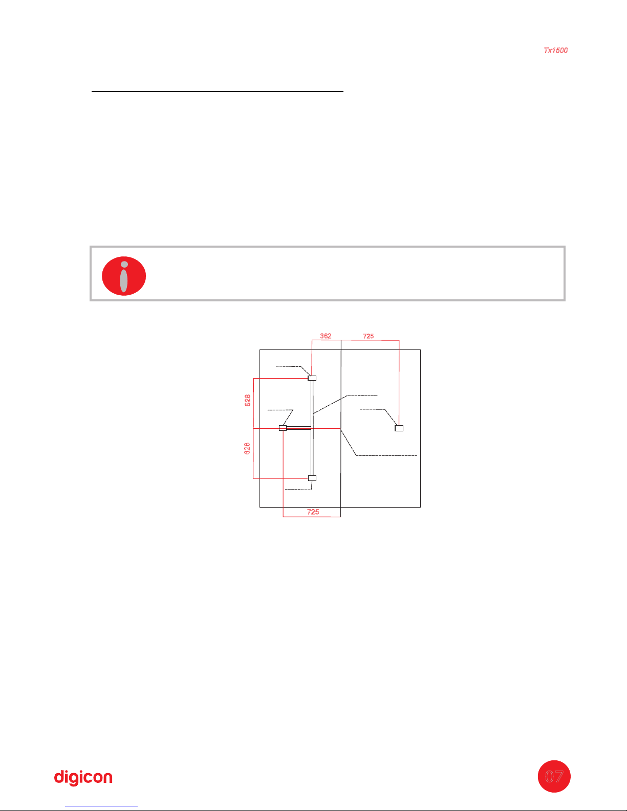
The floor where the turnstile will be fixed must meet the following specifications:
a. 1,6mm x l 1,4mm xDimensions: Direction of flow columns width concrete
height
10 cm;
b. ;Necessary height: 2. meters5
c. ;Level the floor for better product performance
d. ;Floor specification (FCK15 M.P.A. concrete or equivalent)
e. 1,6m
x 1,4m x 2,6m.Floor specification (FCK15 M.P.A. concrete or equivalent)
Power point input and network cable can be on the floor, preferably at point 3 or
overhead pipes.
Obs.:The dimensions of the concrete block and power inputs are only a suggestion.
The client can choose smaller bases (footing) at the fixing points (determined by
template).
List of tools for assembling the Turnstile:
INFORMATION: Illustrative image (measures specified in “mm”).
Duct
Point 4
Reference point
Point 1
Point 3
Point 2
725
628
628
362
725
Torniquete
Tx1500
07
1 socket wrench with
socket of 14 and
17mm;
1 combination wrench
17;
1 socket wrench 10
with extension;
1 ;n.3 Allen wrench
1 n. 5 Allen wrench;
1
medium-sized
Philips screwdriver;
1 medium-sized
screwdriver;
1 hard plastic
hammer
1 plum-line or water
level;
1 silicone tube;
Molykote BR2 Plus
gr
aphite grease;
Step ladder with four
steps
;
Electric drill and drill
bits for concrete with
6 and 14 cm
;
Bolter – 10 parts for
every product.
Page 8
2
th
tep:S Drilling device
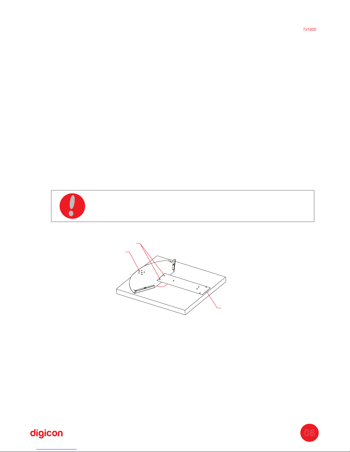
a. It will be necessary to add cardboard or bubble wrap under the device so not to
damage the roof painting when using the drilling demarcations;
b. Screw the device (P1) to the turnstile's roof (P1);
c. Position the assembled parts in the area chosen for installation, observing the flow
of entrance and exit;
d. Observe the desired side for the opening (lock side) of the central support for
maintenance;
e. P ;lace
the roof (P1) and fix tem with screw (P2) and nut (P3)
f. The pre-hole must be done with an Ø6mm drill, so there are no damages to the
device's holes;
g. Remove the device and drill again all the holes with an Ø14mm drill.
Quantity of parts used in this stage:
P1
= 1x Roof
P2 = 1x Drilling device
P3 = 2x M6x15Allen screw
P4 = 2x M6Nut
Obs.: After all demarcations, disassemble the device to use the part later (P1).
90°
P1
P3 - P4
P2
Torniquete
Tx1500
ATTENTION: The place of installation and the direction of entrance
.and exit must be defined alongside the responsible for the place
08
Page 9
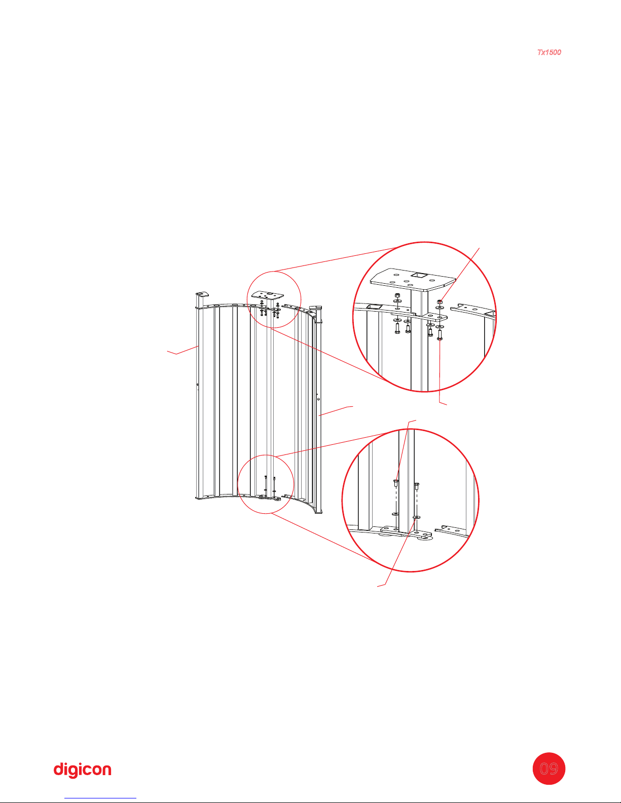
3
th
Step: Assembly of sides with rods or glass sides
Sides with rods:
a. Fit the sides (P5) and (P6) so to form an arch;
b. Screw the sides using washer (P7) and screw (P8); repeat on the four fixing
points (two on the upper part, two on the lower part);
c. Place the screw (P26) with washers (P7) on both sides and on the nuts (P18) to
finish the holes on the arch's upper part.
Quantity of parts used in this stage:
P5
= 1x - 5 side rods
P6 = 1x- 4 side rods
P7 = 8x - D=30,5 x 10,5 x 3mmWasher
P8 = 4x - M10 x 20Hexagon head screw
P18 = 2x - M10Nut
P26
= 2x - M10 x 30Hexagon head screw
This assembly will result in the set (P23) – Assembling the arch's sides
P5
P18
P26
P8
P7
P6
Torniquete
Tx1500
09
Page 10
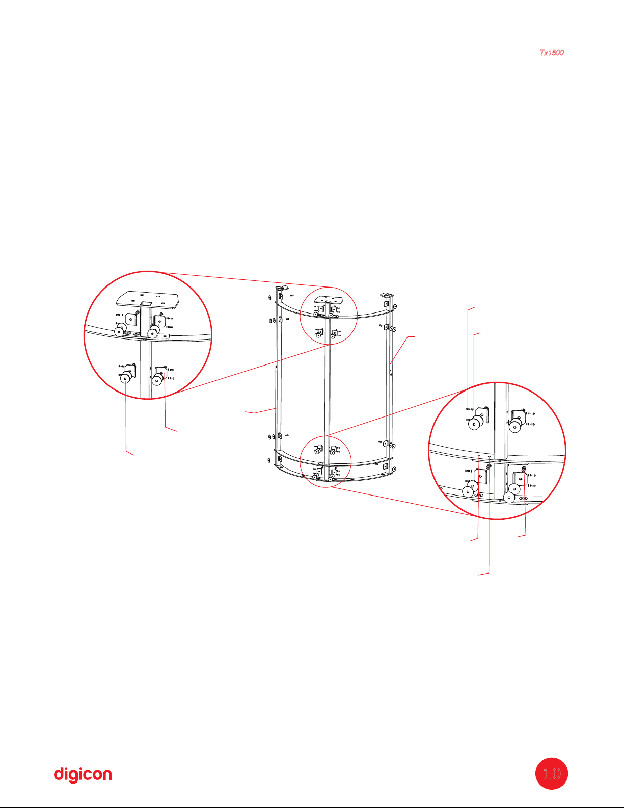
Glass sides:
a. Fit the sides (P39) and (P40) so to form an arch;
b. Screw the sides using washer (P41) and screw (P8); repeat on the four fixing
points (two on the upper part, two on the lower part);
c. Fix the glass support (P42) to the rods' inner parts using washers (P25) 2x and
screws (P20) 2x in each support;
d. Fit the nut for the glass support (P45) to the glass support (P42); after the
nut was placed on the other side, place the two PVC washers (P44);
e. Repeat items “c” and “d” 16 times in each support fixation.
Quantity of parts used in this stage:
P8
= 4x - Hexagon head screws M10 x 20
P20 = 32x - M4 x 12cross head screw
P25 = 32x - D4flat washer
P39 = 1x - 2 side rods
P40 = 1x - 1 side rod
P41 = 4x - flat washer D10
P42
= 16x - glass support
P44 = 32x - PVC washer
P45
= 16x - glass support nut
This assembly will result in the set (P48) – Assembly of glass sides.
Torniquete
Tx1500
10
P39
P45
P41
P25
P20
P42
P44
P8
P40
Page 11
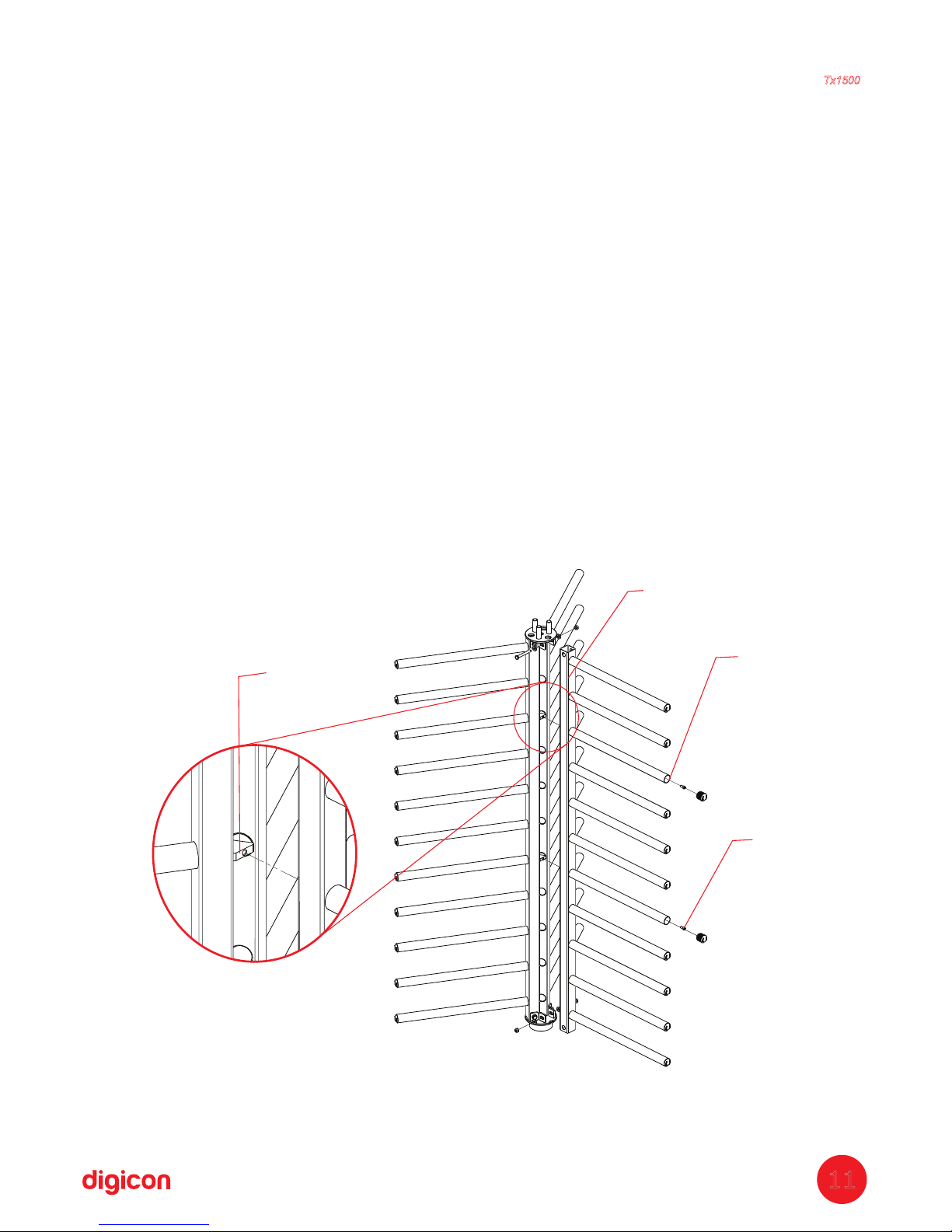
4
th
tep:S Assembling central arms
a. fix the inner triangle (P9) to one of the arms (P10) using the screw and the spring
washer (P11); repeat it for the arm's two fixing points (P10). Fixing this part is done
internally in the arms that have no buffer. Do not fasten the screw, simply position it.
b. Place the second arm (P10), fixing it to the inner triangle (P9) using the screw ad
the spring washer (P11). Repeat it for the arm's two fixing points (P10). Fixing this
part is done internally in the arms that have no buffer. Do not fasten the screw, simply
position it.
c. Place the third arm (P10), fixing it to the inner triangle (P9) using the screw ad the
spring washer (P11). Repeat it for the arm's two fixing points (P10). Fixing this part is
done internally in the arms that have no buffer. Do not fasten the screw, simply
position it.
d. Fit the lower base set (P14) to the lower part of the assembled arms (P10); place
the washers (P17) 2x, screw (P16) 1x, and nut (P18) 1x in each of the holes 3x. Do
not fasten the screw to the nut, only position it.
e. Fit the upper base set (P15) to the upper part of the assembled arms (P10); place
the washers (P17) 2x, screw (P16) 1x, and nut (P18) 1x in each of the holes 3x. Do
not fasten the screw to the nut, only position it.
Torniquete
Tx1500
11
P11
P11
P9
P10
Page 12
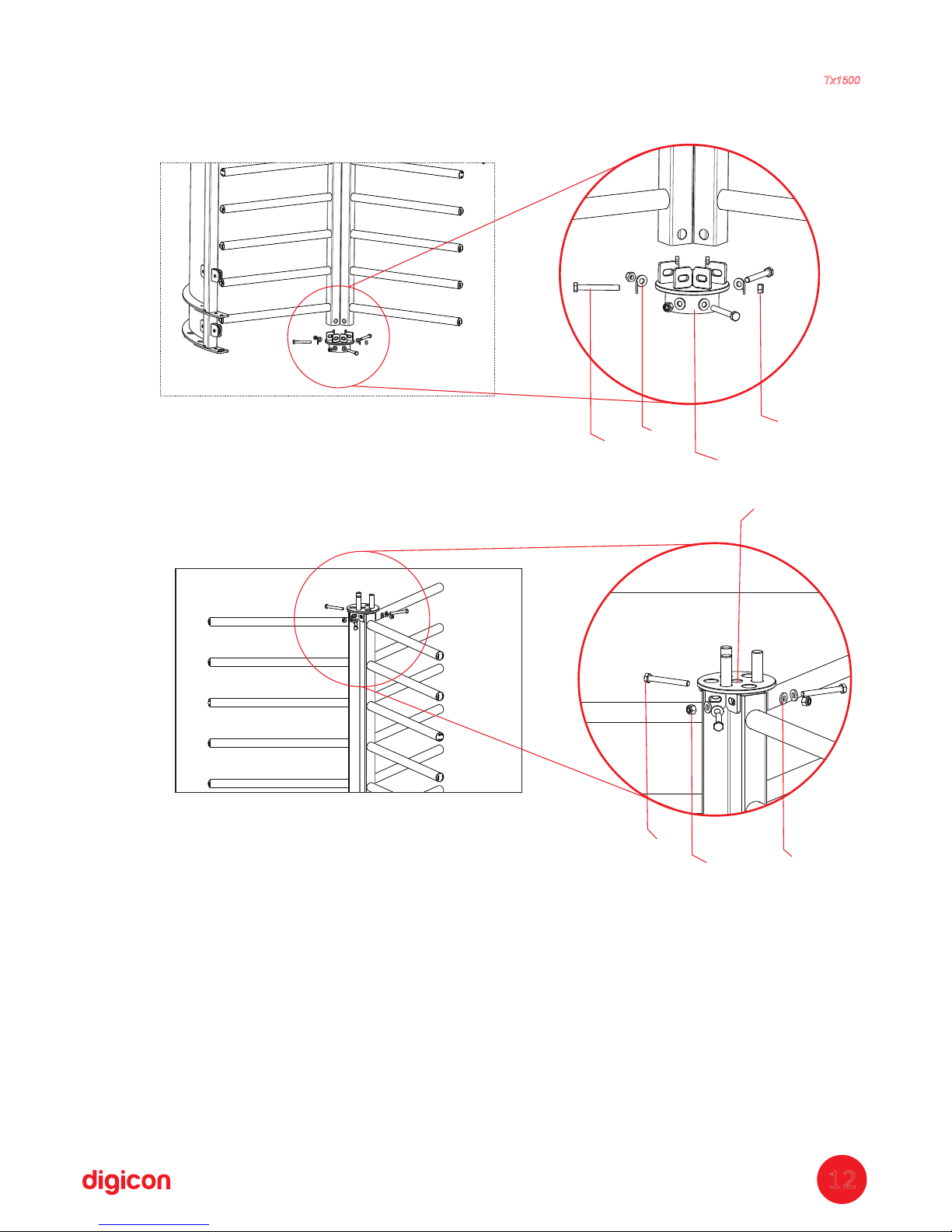
P18
P16
P14
P17
Base set assembled. Do not fasten it.
P15
P17
P16
P18
Upper base set assembled. Do not fasten it.
Quantidade de peças usadas nesta etapa:
P9 = 2x - Triangle
P10 = 3x - Central arm
P11 = 6x - M8 x 10Allen screw
P14 = 1x - Lower base
P15 = 1x - Upper base
P16 = 6x - M10 x 80Hexagonal head screw
P17 = 12x - D=22 x 10,5 x 3mmWasher
P18 = 6x - M10Nut
This assembly will result in the set (P28) – Central arms
Torniquete
Tx1500
12
Page 13
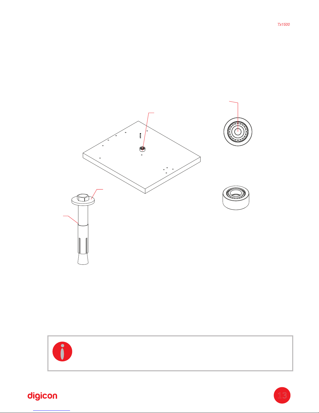
5
th
tep:S Fixing the bearing support
a. ;Replace the fastener's washer (P21) for the washer (P7)
b. ;Use the fastener (21); does not accompany the product
c. Place silicone rubber under the bearing; then fix the bearing support (P19) to
the central hole, as shown in the image
.
Quantity of parts used in this stage:
P7
= 1x - Washer D= 30,5 x 10,5 x 9mm
P19 = 1x – Bering
P21 = 1x - Fastener
Torniquete
Tx1500
13
ISOMETRIC VIEW
P19
UPPER VIEW
Screw must be
centralized in
the bearing.
P7
P21
INFORMATION:
Add more Molykote grease to the bearing since the grease sent is for
transport only.
Repeat the operation above in the both rotating centers.
Page 14
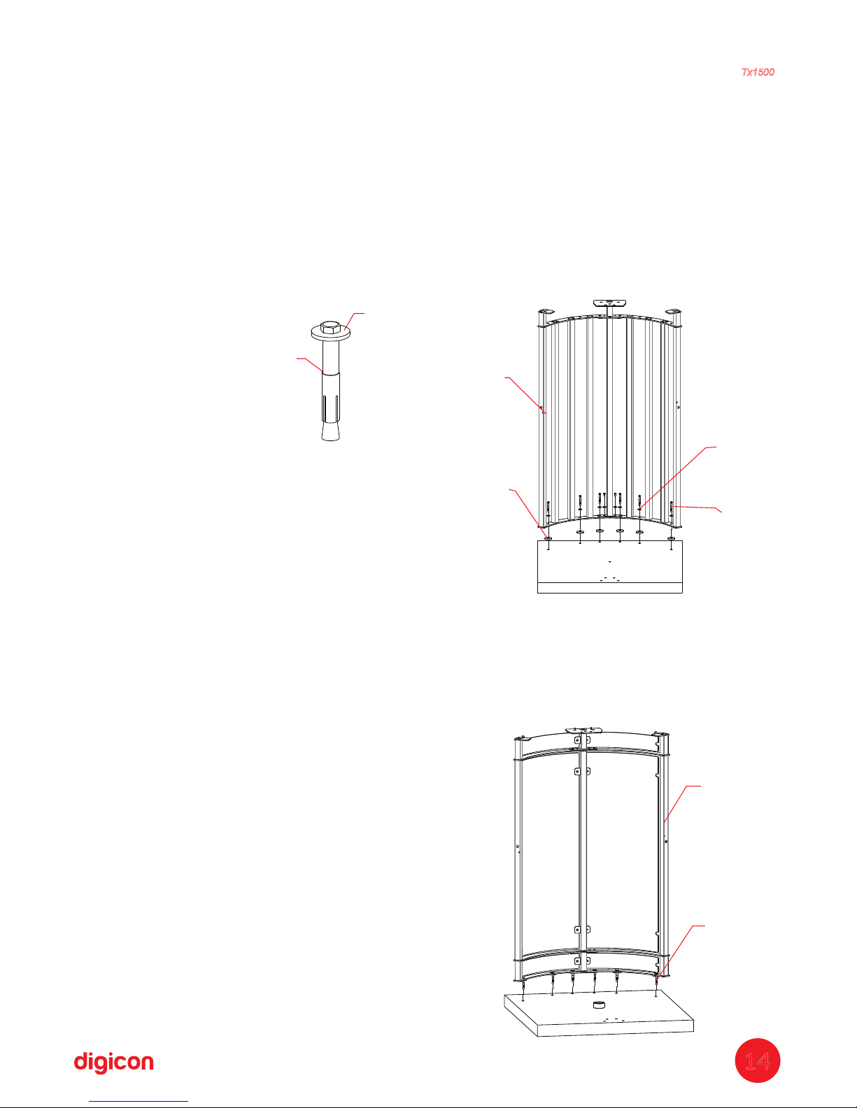
6
th
tep:S
Fixing the sides
Fixing the sides with rods:
a. ;Set the coincident flanges (P22) in the holes of the floor
b. Align the assembly of the sides with grid (P23) over the flanges, coinciding
with
the holes;
c. ;Replace the fastener's washer (P21) by the washer (P7)
d. ;
Place the fasteners (P21) in all fixing points
e. ;
Level the rod and wedge the base with washers, if correction is necessary
f. .Fasten all the screws
Q
uantity of parts used in this stage:
P7
= 6x - Washer D=30,5 x 10,5 x 3mm
P21 = 6x - Fastener
P22 = 6x - Flange
P23 = 1x (Assembly obtained in step 3) -
Assembly of arch's sides
Fixing
glass sides:
a. Align the assembly of the sides to the glasses (P48), coinciding with the holes;
b. Place the fasteners (P21) in all fixing points;
c. Level the rod and wedge the base with washers, if correction is necessary;
d. Fasten all the screws.
Quantity of parts used in this stage:
P21 = 6x -Fasteners
P48
= 1x - Assembly of sides to the glasses
P23
P7
P21
P22
P48
P21
Torniquete
Tx1500
14
P7
P21
Page 15
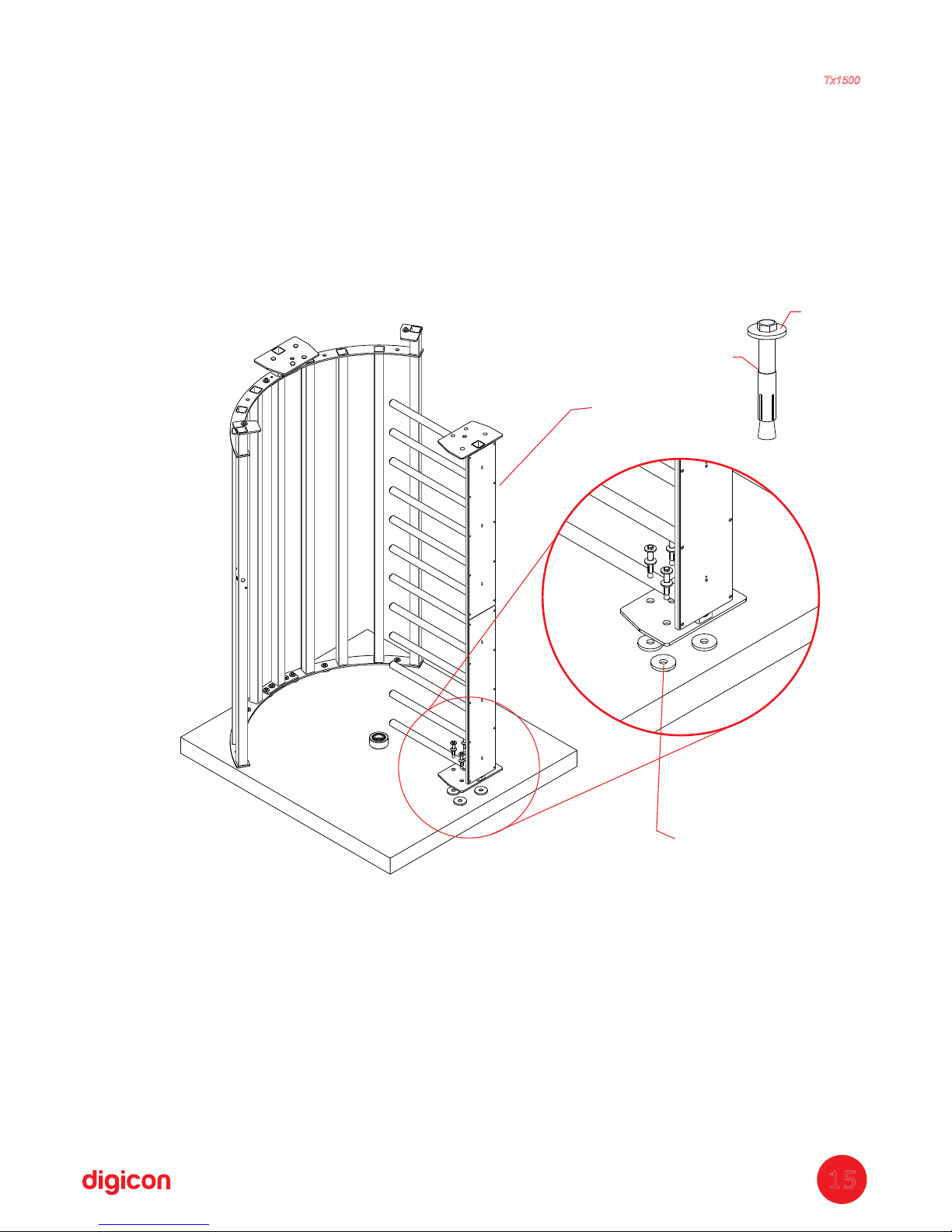
P22
P24
P7
P21
7
th
tep: Fixing the stationery armS
a.
Set the coincident flanges (P22) in the holes of the floor.
b. Set the stationery arm (P24) over the flanges and coinciding holes;
c. Replace the fastener's washer (P21) by the washer (P7);
d. Place the fasteners (P21) in all fixing points;
e. Level the rod and wedge the base with washers, if correction is necessary;
f. Fasten all the screws.
e. Level the column and wedge it with washers, if necessary;
Quantity of parts used in this stage:
P7
= 4x - D=30,5 x 10,5 x 3mmWasher
P21 = 4x - fastener
P22
= 4x - Flange
P24 = 1x - Stationery arm
Torniquete
Tx1500
15
Page 16
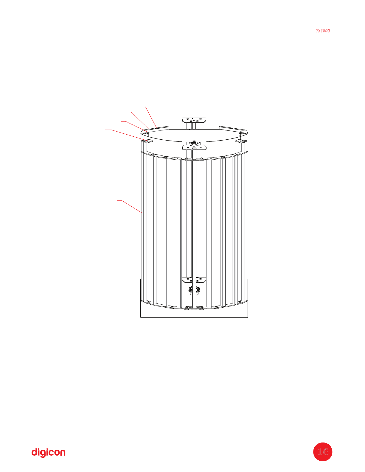
8
th
tep: Fixing the roofS
a. Place the roof over the side (P23 or P48);
b. Screw only the edges of the roof, using in each fixation 2 washers (P7), screw
(P26), and nut (P18). The center will be fastened later, alongside the coverage.
Obs.: Place the screw from the bottom upwards.
Quantity of parts used in this stage:
P1
= 1x - Roof
P7 = 4x - D=30,5 x 10,5 x 3mmWasher
P18 = 2x - M10nut
P26 = 2x - M10 x 30Hexagonal head screw
P23 = Side assemble with rods
P48
= Side assemble for glass
P1
P18
P7
P26
P23 OR P48
Torniquete
Tx1500
16
Page 17
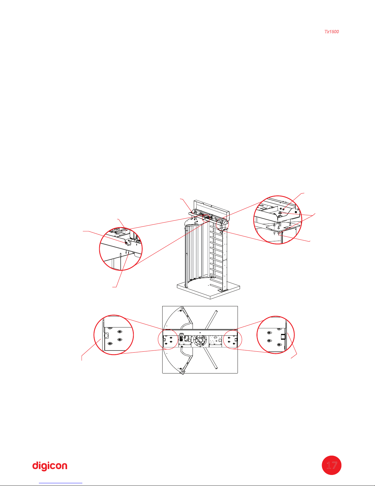
9
th
Step: Fixing the coverage
a. Check the height from the floor to the upper part of the roof (P1) – 2.1
meters with tolerance of 5mm;
b. Place the turnstile coverage (P27) over the roof (P1) and the stationery arm
(P24);
c. In each fixation, use 2 washers (P7), screw (P26), and nut (P18). Obs.: place
the screw from the bottom upwards. Do not fasten it.
d. Fix the roof (P1) with the turnstile coverage (P27), using screw (P3) and nut
(P4);
e. Align the turnstile coverage (P27) with the central hole, considering 70cm
plus the hole radius of 11.5cm = total 81,5 cm of the inner central rod of the
structure to the hole's larger size and the inner stationery column in relation to
the hole's large side. Details in the figure below:
f. After aligning, fasten the screws in all the fixing points of the turnstile
coverage (P27).
Quantity of parts used in this stage:
P3
= 2x - M6 x 15Allen screw
P4 = 2x - M6Nut
P7
= 16x - D = 30,5 x 10,5 x 3mmWasher
P18 = 8x - M10Nut
P26
= 8x - M10 x 30Hexagonal head screw
P27
= 1x - Coverage
P30
= 2X - D= 6Plat washer
Coverage face must be
aligned to stationery arm
Alignment detail
Alignment detail
Coverage face must be
parallel to the roof's side
P18
P7
P26
Torniquete
Tx1500
17
P27
P4
P3
P30
Page 18
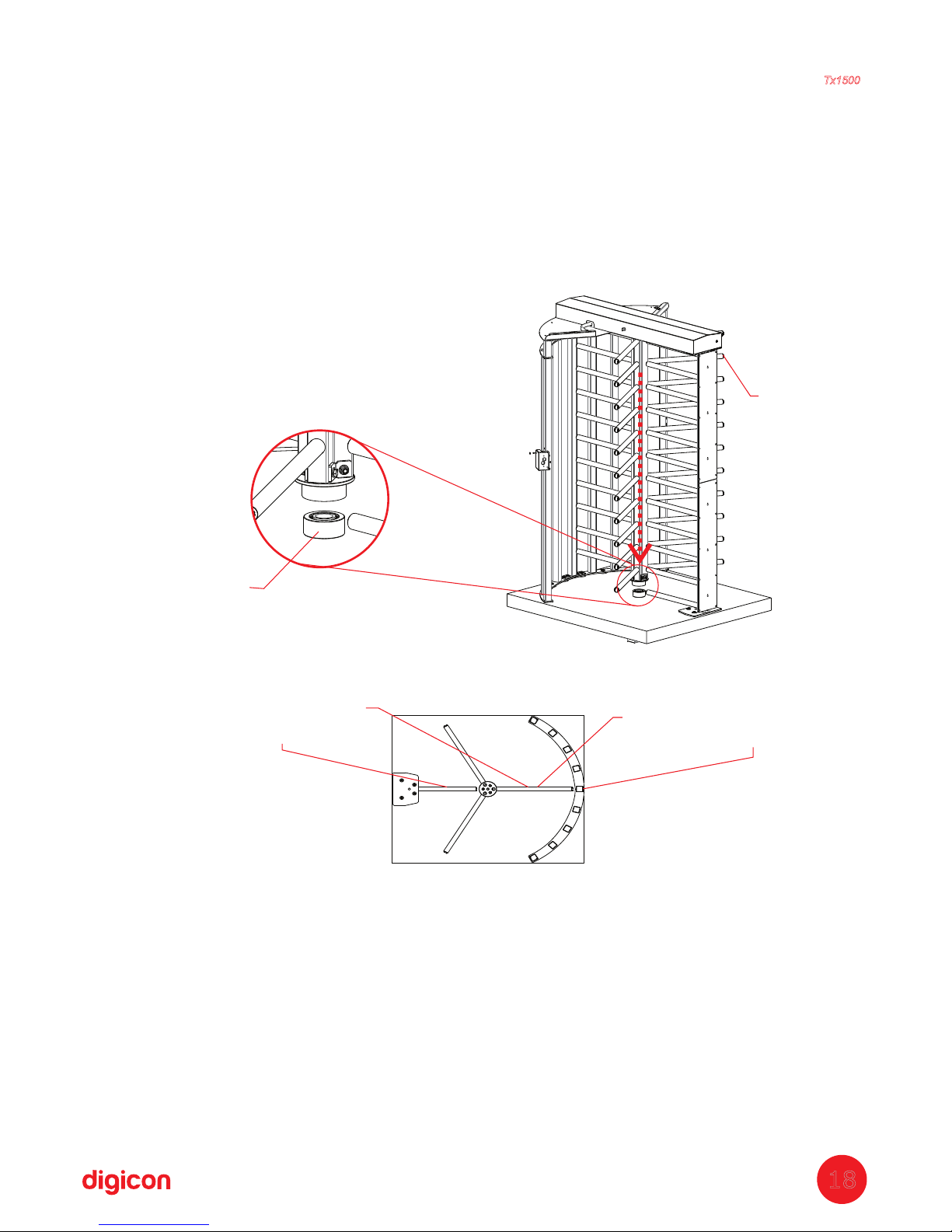
10
th
Step: Fit the central pivoting arm
a. Grease the bearing support (P19). (We recommend Molykote BR-2 Plus
grease);
b. Fit the central arms assembly (P28) in the bearing support (P19). In this stage,
the assembler or mechanic cannot drop the central arms assembly, so we suggest
an auxiliary assembler or to tie the central arm to the structure;
c. Align one of the line of arms to the stationery arms, as shown in the image:
Quantity of parts used in this stage:
P28
= 1cj (Assembly obtained in the 4 step of this Manual) – Central arm
th
Fitting of the arms in the base
P19
P28
Align pivoting arm
with stationary arm
Align pivoting arm with
.central metalon
Position of the pivoting arm in the structure.
This must be the pivoting arm's position to fit the locking
system detailed in the next step.
Torniquete
Tx1500
18
Page 19
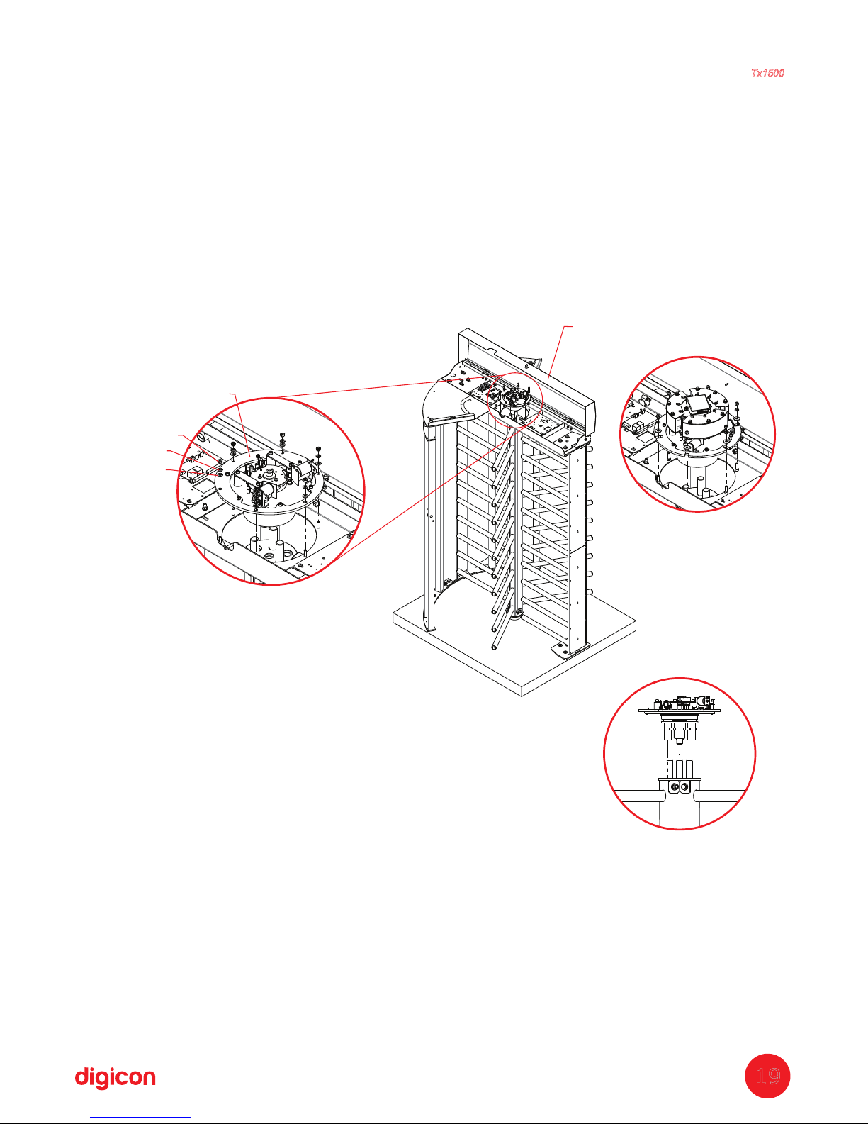
11
th
Step: Fitting of locking system
a. Fit the locking system (P29) in the pivoting arm assembly (P28), maintaining the
arms' alignment, as seen in the 10 step; fit it in the coverage (P27);
th
b. Fit the locking system (P29) with washer (P30), spring washer (P31), and nut
(P32). 6 fixings;
c. After the locking system (P29) is fixed (and only then), rotate the pivoting arm
several times to settle the bearing supports and fasten all the screws in the pivoting
arm assembly (P28).
Quantity of parts used in this stage:
P29
= 1x - Locking system
P30 = 6x - D6Flat washer
P31 = 6x - D6Spring washer
P4 = 6x - M6Nut
P29
P4
P31
P30
P27
Torniquete
Tx1500
19
Locking system
Disk with ablong
Stainless steel
turnstile
Page 20
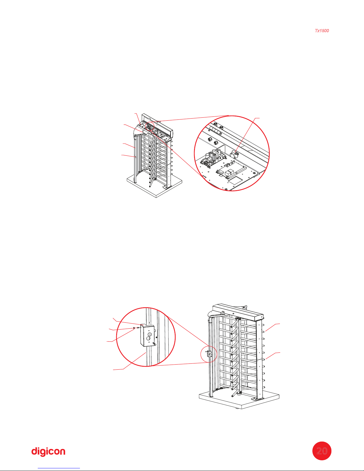
12 ;
th
Step: Cable passage
a. Pass the power and network cables through a hose (P33);
b. Put one of the hose's ends (P33) inside the coverage (P27) and the other end
inside the side structure (P23 or P48);
c. Inside the coverage (P27), place the clamp (P34) on the hose's end (P33) to avoid
it being torn;
d. Repeat the procedure above on both sides (entrance and exit) of the turnstile.
Quantity of parts used in this stage:
P33
= 2x - Hose
P34 = 2x - Clamp
13
th
tep: Assembling the card reader bracketS
a. Fix the card reader bracket (P35) with a screw (P36); repeat on both sides;
b. Place the cowl cover (P37) in all holes, 4x in each bracket;
c. Place the arms cover (P38) in the arms assembly (P28).
Quantity of parts used in this stage:
P35=
2x - Reader bracket
P36=
4x - M4x12mmAllen screw
P37=
8x Cowl cover
P38
P28
The holes of the bracket always
have to stay in the inner side
of the turnstile on both sides
P35
P36
P37
P34
P27
P33
P23
Cable output
for readers
Torniquete
Tx1500
20
Page 21
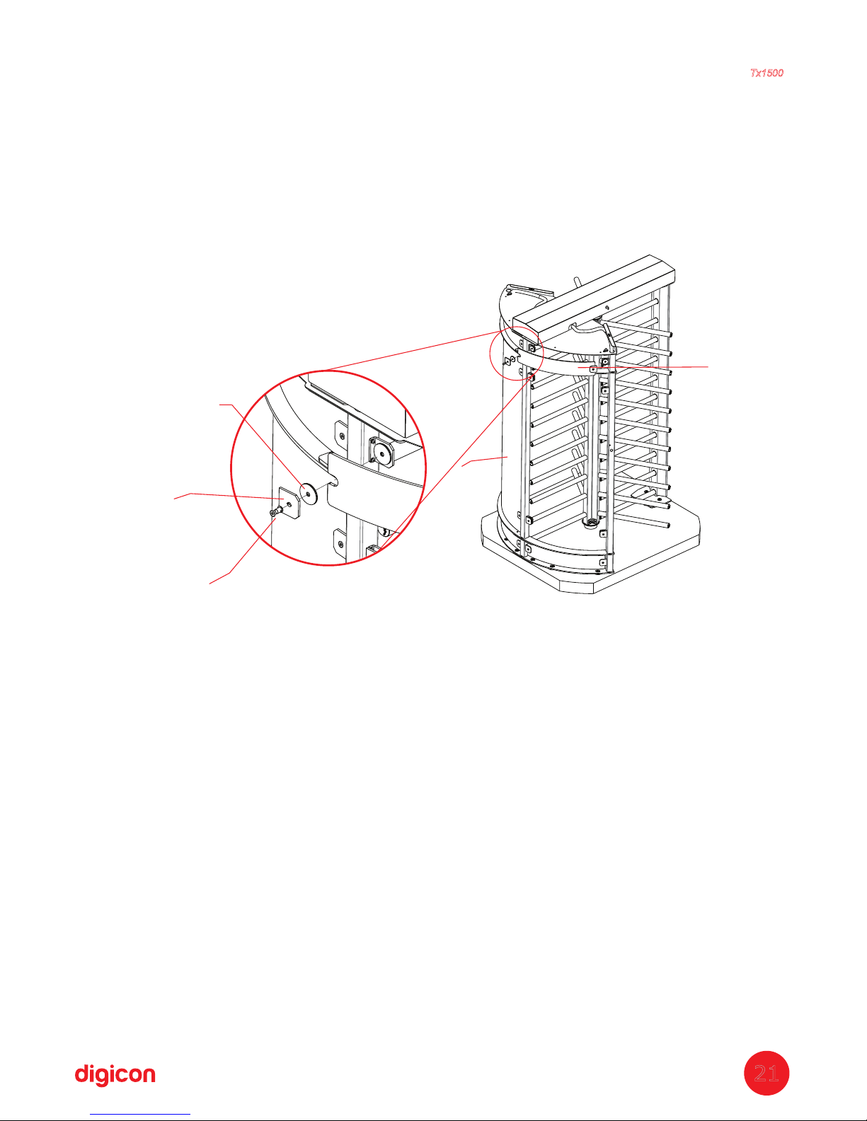
14 tep: Assembling sides glasses
th
S
a. Place the glass (P49) and fix it using washers (P44) 2x, the glass fixing bracket
(P43), and screw (P46).
b. Place the glass (P50) and fix it using washers (P44) 2x, the glass fixing bracket
(P43), and screw (P46).
Quantity of parts used in this stage:
P43 = 16x
- Glass bracket
P44 = 32x - PVC washer
P46 = 16x -Fixing screw
P49 = 4x - Smaller glass arch
P50 = 2x - Larger glass arch
P49
P44
P43
P46
P50
Torniquete
Tx1500
21
Page 22
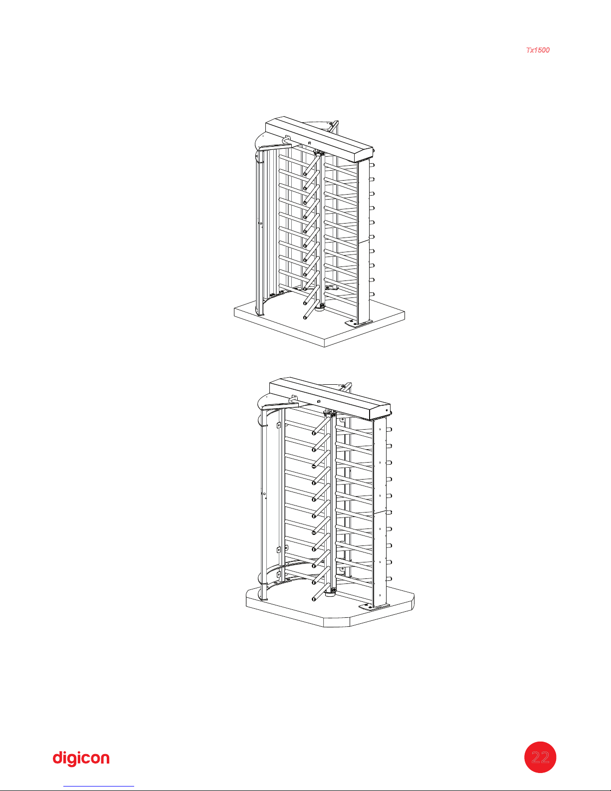
Turnstile with glass sides (gray, blue, and stainless steel)
Turnstile with grid sides (gray, blue, and stainless steel)
15 tep: Assembled Turnstile
th
S
Torniquete
Tx1500
22
Page 23

5. Legenda
P1 - - 01 01 01Turnstile's roof
P2 - - 01 01 01 Por PedidoDevice for drilling
P3 - - 02 02 02Stainless steel Allen M6x15 screw
P4 - - 08 08 08Self-locking Hexagonal nut M6
P5 - - 01 01 015 rods turnstile side
P6 - - 01 01 014 rods turnstile side
P7 - D=30,5x10,5x3mm - 39 39 39washer
P8 - -
04 04 04Stainless steel hexagonal head screw M10x20
P9 - - 02 02 02Inner triangle
P10 - - 03 03 03Central column arm
P11 - - 06 06 06Stainless steel Allen M8x10 screw
P14 - - 01 01 01Central column lower base set
P15 - - 01 01 01Central column upper base set
P16 - 06 06 06-Stainless steel hexagonal head screw M10x80
P17 - 12 12 12Washer D=22x10,5x3mm -
P18 - 18 18 18Self-locking Hexagonal nut M10 -
P19 - 01 01 01Lower bearing set -
P20 - -Stainless steel cross head M4x12 screw
P21 - (C38312 3,1-2-3-8) - 11 11 11Fastener Not provided
P22 - 10 10 10Turnstile lower Flange -
P23 - 01 01 01Sides with grid assembly 3 step
rd
P24 - 01 01 01– tationery arm setS
P25 - -Stainless steel flat washer D4
P26 - -
12 12 12Stainless steel hexagonal head M10x30
P27 - - 01 01 01Turnstile coverage
P28 - - 01 01 01Central arms 4 step
th
P29 - - 01 01 01Turnstile's locking system set
P30 - - 06 06 06Stainless steel flat washer D6
P31 - - 08 08 08Stainless steel spring washer D6
P33 - l - 02 02 02Flexible hose 1m each
P34 - - 02 02 02Clamp
P35 - - 02 02 02Card reader bracket
P36 04 04 04– tainless steel Allen M4x8 screw -S
P37 - - 08 08 08Cowl cover
Torniquete
Tx1500
23
Descrição das Peças CZ AZ IX VDR Observações
01
01
02
08
29
04
02
03
06
01
01
06
12
18
01
32
11
04
01
32
12
01
01
01
06
08
02
02
02
04
08
Page 24

P38 –finishing cover - 06 06 06 06
P39 - 2 rods turnstile side - 01
P40 - 1 rod turnstile side - 01
P41 – stainless steel flat washer D10 - 04
P42 – glass stationery bracket - 16
P43 – glass fixing bracket - 16
P44 – PVC washer - 64
P45 - Nut for glass bracket - 16
P46 – screw for glass bracket - 16
P48 – side assembly for glasses - 01 3 step
rd
P49 – smaller glass arch - 04
P50 – larger glass arch - 02
C
aption of table above:
GRAY – grayturnstile
BLUE – blue turnstile
S. STEEL – stainless steel turnstile
GLASS – turnstile with glass sides (it can be done in the colors gray, blue, and
stainless steel)
Torniquete
Tx1500
24
Descrição das Peças CZ AZ IX VDR Observações
Page 25
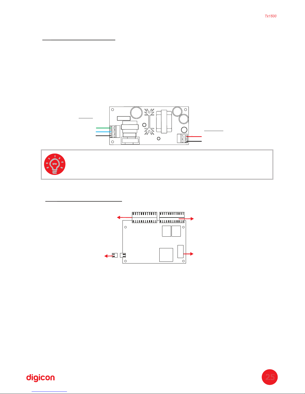
7. Control board
Turnstile Tx1500's control board was designed to meet most technologies of access
control
terminals in the market. The controller have mechanical features and layout
perfectly suited for the Turnstile Tx1500's needs and it is one of the best options for
the equipment's operation.
The following images show the control board with its straps, connectors, and
dipswitch, as well as the location of the power supply and the control board.
The table below describes the functions of the control board's connectors:
6.Power supply
This power supply was especially designed for the line CATRAX. Among the main
advantages of this optional item, is its adaptation capability to the voltage variations
often found in installation sites – the input voltage can vary between 100 and 240
V .ac
The supply's specific technical features, protections and dimensions were carefully
tested and approved in hostile temperature and environmental conditions, which
ensures the adequate power supply to the equipment's performance. Besides the
input and output voltages indicated in the image below, the supply has a shortcircuit and overheating protection.
INPUT:
100 A 240 Vac
OUTPUT:
Ground
Neutral
Phase
12V 5% / 3A
+
-
GND
TIP: The power supply can be mounted to the board's support hat
accompanies the Turnstile.
25
Torniquete
Tx1500
Cn1
Cn2
Ds1
Cn8
Page 26

26
Torniquete
Tx1500
Signal Name/Description
CN1 INPUTS
1 +Vext1 (enables turn through voltage)
2 HAB1 (enables turn through dry contact – from right to left)
3 GND
4 Vext2 (enables turn through voltage)
5 HAB2 (enables turn through dry contact – from left to right)
6 GND
7 +12Vdc (available to auxiliary – maximum 500 mA)
8 CLOCK1 (input for reader from left to right)
9 DATA1 (input for reader from left to right)
10 CLOCK2 (input for reader from right to left)
11 DATA2 (input for reader from right to left)
12 GND
13 PROG1 (programs direction)
14 PROG2 (programs direction)
15 PIC1 (controls frontal pictogram 1)
16 PIC2 (controls frontal pictogram 2)
CN2 OUTPUTS
1 NO or NC Contact (HAB1 return)
2 Contact C (HAB1 return)
3 NO or NC Contact (HAB2 return)
4 Contact C (HAB2 return)
5 Output for indicative X (open collector NPN – maximum 500 mA) orange wire
6 Output for arrow > (open collector NPN – maximum 500 mA) blue wire
7 Output for arrow < (open collector NPN – maximum 500 mA) green wire
8 +12Vdc (indicative arrows’ power) red wire
9 GND (indicative arrows’ power) black wire
10 + solenoid of badge collector box
11 - solenoid of badge collector box
12 Sound signal (open collector – NPN)
CN3 SERIAL RS-485
1 DATE 2 DATE +
3 GND
CN4 SIDE PICTOGRAM 2
1 +12Vdc (indicative arrows’ power)
2 Output for indicative X (open collector NPN – maximum 500 mA)
3 Output for arrow > (open collector NPN – maximum 500 mA)
4 GND (indicative arrows’ power)
CN5 SIDE PICTOGRAM 1
1 +12Vdc (indicative arrows’ power)
2 Output for indicative red arrow (open collector NPN – maximum 500 mA)
3 Output for green arrow (open collector NPN – maximum 500 mA)
4 GND (indicative arrows’ supply)
CN6 INPUT/OUTPUTS
1 input or output 1 – configure at S4 (IN or OUT)
2 input or output 2 - configure at S5 (IN or OUT)
3 GND
4 +12Vdc
CN7 SERIAL RS-232
2 TX
3 RX
5 GND
CN8 POWER – POWER INPUT
1 +12Vdc power input
2 GND power input
CN9 BOX SENSOR
1 LED anode
2 box signal
3 GND
4 GND
CN10 ELECTROMAGNETS
1 + electromagnet 1
2 - electromagnet 1
3 + electromagnet 2
4 - electromagnet 2
CN11 OPTICAL SENSORS
1 sensor 1 signal
2 LED 1 anode
3 sensor 2 signal
4 GND
5 LED2 anode
Page 27

27
Torniquete
Tx1500
Passage direction
PROG1 (pin 13)
PROG2 (pin 14)
Free in both directions Open Open
Controlled from left to right GND Open
Controlled right to left Open GND
Controlled on both sides GND GND
INFORMATION:
- ide pictogram 1 and 2 refer to the devices located on top of theS
equipment.
-The cables of the optical sensors (CN11) and the electromagnets
(CN10) are provided alongside Tx1500.
-The cable of the box sensor (CN9) is provided alongside the
collecting box kit (optional).
INFORMATION: PIC1 and PIC2 refer to the pictograms located on
each side of the equipment.
PIC1 (pin 15) PIC2 (pin 16) Pictogram 1 Pictogram 2
Open
Open
GND
GND
Open
GND
Open
GND
Red arrow
R
ed arrow
Red arrow
Red arrow
Green arrow
Green arrow
Green arrow
Green arrow
NO or NC Contact
Particularly about the CN11 connector, pins 13 and 14: Turnstile Tx1500 can be
configured
as follows to determine direction passage:
Pins 15 and 16, which control the side pictograms, must be configured
thusly:
The following sections concern important aspects of the control
board configuration
and connections of .Tx1500
7.1 Inputs
The input signals or passage clearance (HAB1 and HAB2) can be originated by a relay
contact, pushbutton contact, tension from 5 to 24 V / c, from 110 to 220 V / c. Toac d ac d
enable passage t
Page 28

Enabling passage through tension pulse is shown in the image below. It is necessary
to observe the polarity of the V c voltages and to use an external resistor for highd
voltages (110V and 220V).
The control board also has inputs for optical sensors (CN11) that monitor rotation
without mechanical wear, and two opto-isolated inputs to clear the
Turnstile Tx1500
if required.
7.2 Outputs
T
urnstile Tx1500
board has outputs for return signals, electromagnets, pictogram,
collecting box, and sound alarm.
Return signals
Return signals indicate the moment and direction of passage and are originated at the relay –
normally open contact (NO) or normally closed contact (NC). Connect the outputs according
to the image below:
E
lectromagnets
Electromagnets are activated for blocking the turnstile. Opposite to the traditional
solenoids, electromagnets do not cause abrasion between the coil and the locking
device, avoiding malfunctions. Moreover, the activation is done through a transistor,
and not a relay, avoiding the electromagnet to be blown due to the “contact wielding”
(there is no mechanical wear).
Sound alarm
The sound alarm output is activated by a NPN transistor (maximum 500 mA) every
time that Turnstile Tx1500:
- eceives a clearance signal (two short rings)R
-Is not cleared and is forced during 1 second (1-second ri
28
5 a 24 Vca ou cc
110 a 220 Vca ou cc
Torniquete
Tx1500
Page 29

29
Torniquete
Tx1500
29
Connect the outputs according to the following image:
Sound alarm
Maximum current: 500mA
Page 30
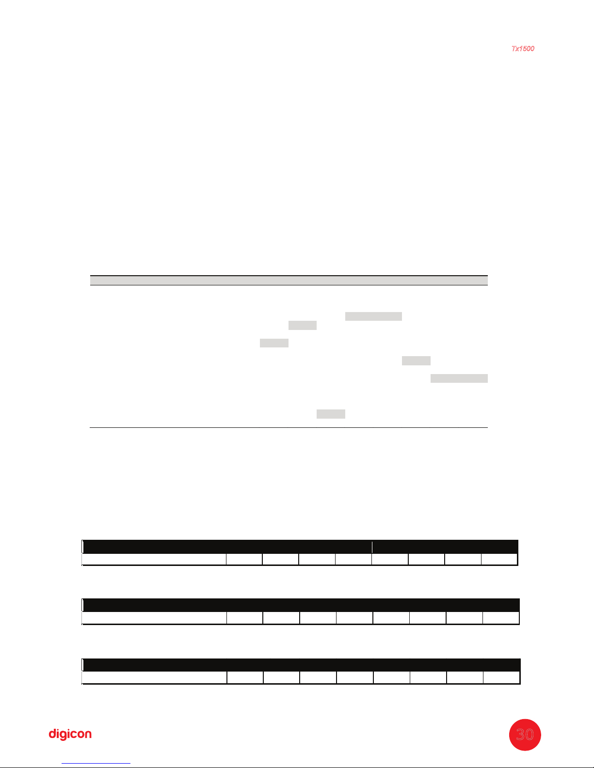
Torniquete
Tx1500
7.3 Configuration of control board – Switch Ds1
The switch (or dipswitch) DS1 allows programming the following actions:
-passage direction
-Maximum time for turns
-NO inputs (relay or pushbutton contact normally open and without input voltage),
enabling passage in face of these signals; or NC inputs (relay or pushbutton contact
usually closed and with input voltage), enabling passage in the absence of these
signals.
-enabling of a signal for a sound alarm if the access control remains at mid turn for more
than 5 seconds.
To program DS1, put each pin in the desired position, according to the table below.
01020304050607
08
Cleared in both directions - - - OFF OFF - - Blocked from left to right - - - ON OFF - - Blocked form right to left - - - OFF ON - - Blocked in both directions - - -
ON
ON
- - -
NO inputs -
ON
- - - - - NC inputs - OFF - - - - - Enables sound signal
ON
- - - -
-
- -
Disables sound signal OFF - - - -
-
- -
Enables sound signal in mid-turn - - - - -
ON
- Disables sound signal in mid-turn - - - - - OFF - Wait until first turn - - - - - -
ON
ON
Wait for 5 seconds - - - - - - OFF ON
Wait for 10 seconds - - - - - - ON OFF
Wait for 15 seconds - - - - - - OFF OFF
Habilitation per border* - -
OFF
- - - - -
Habilitation per level** - - ON - - - - -
* “Habilitation per border” means that Tx1500 will be enabled by a pulse at the entry border
(NC inputs) or exit border (NO inputs).
** “Habilitation per level” means that Tx1500 will remain free as long as there is an input
signal.
1 - To receive a relay pulse (NO contact), clear the turning and wait to turn for 10 seconds:
1234567
8
Configuration - ON OFF ON ON - ON OFF
2 - To leave the clockwise direction always cleared and, when the HAB2 (anti-clockwise)
clearance signal is received, clear passage for undetermined period:
1234567
8
Configuration - ON OFF OFF ON - ON ON
3 - To clear the turning while the relay has the contact closed and, as soon as the relay contact
is open, remove clearance:
1234567
8
Configuration - ON ON ON ON - ON ON
30
Page 31

Torniquete
Tx1500
7.5. Serial communication
Turnstile Tx1500 Duo
's control board allows serial configur
ation of the equipment. The
communication protocol used is as follows:
Where:
- represents beginning of transmission (0x02)STX
- is the byte with the least significant size componentSize(LSB)
- is the byte with the most significant size componentSize(MSB)
- is the information sent to the equipment (one or two bytes);Commands
- is the XOR operation for all bytes sent, from STX to CommandsBCC
The following table shows the enabling commands that can be sent to
Turnstile Tx1500
Duo:
The following table shows the return commands that can be sent by the equipment:
The
following table shows some examples of command:
STX Tamanho(LSB) Tamanho(MSB) Comandos BCC
HEXA
ASCII
FUNCTION
0x48 H
Clears direction from right to left
0x41 A Clears direction from left to right
0x44 D Clears both directions
0x43 C Back to controlling (command used to leave free state)
0x4C L Turnstile free (include free direction <0x4C> + <0x48>)
0x53 S
Direction programming (include direction to be programmed <0x53>
+ <0x48>)
HEXA
ASCII
FUNCTION
0x48 H free from right to left
0x06
ª
ACK, indicates command OK
0x15 §
NACK, indicates invalid command
0x1A
®
Return command form right to left (RET1)
0x1B
¬
Return command from left to right (RET2)
Free from left to right (1 passage):
0x02 0x02 0x00 0x48 0x48
Configure from left to right as always free:
0x02 0x03 0x00 0x4C 0x48 0x05
Return OK command:
0x02 0x02 0x00 0x06 0x06
ATTENTION:
- Size corresponds to the number of bytes sent (total command
bytes: 1).
- The protocol communication rate is 115,200 bps.
31
Page 32
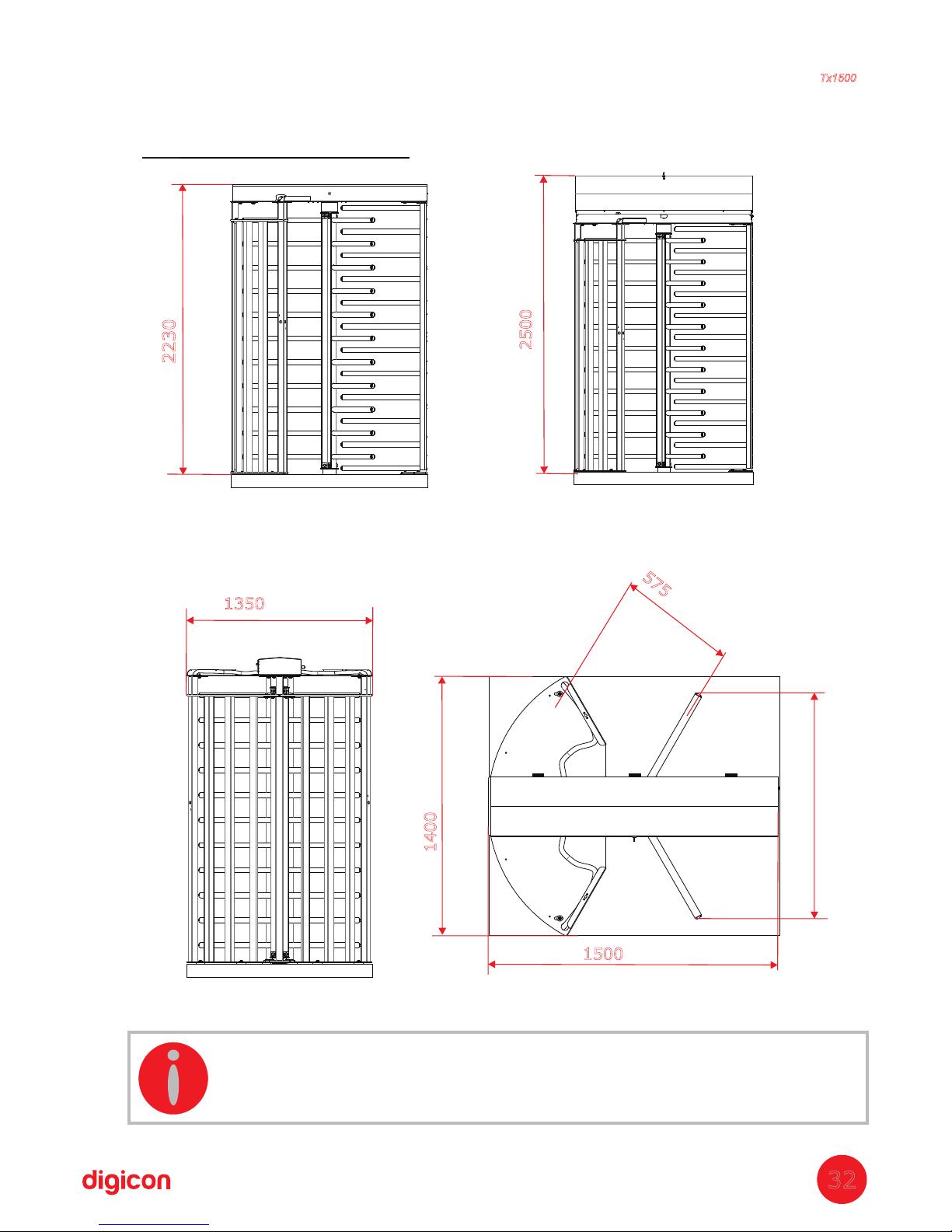
8.Dimensions
Torniquete
Tx1500
32
2230(87.795")
1350(54.149")
1400(55.118")
1500(56.055")
1166
2500(98.425")
Closed cover
Open cover
Side view
Upper view
575
(22.637")
INFORMATION: All measures presented in the images are in
millimeters .(Inches)
Page 33

9.Warranty and technical assistance
Digicon is responsible for the project, skilled labor, and quality of the materials used in the
manufacturing of our products, ensuring that the equipment and all parts are free of
manufacturing defects or problems. Digicon commits itself to replace or repair, as we choose,
any part or equipment presenting manufacturing defects without any costs to the buyer, in our
factory in Gravataí or our branch office in São Paulo, in the conditions set below:
1. The buyer is responsible for the costs of shipping (return service) of the product to the
factory
in Gravataí or the branch office in São Paulo.
2. The warranty period is counted from the date of emission of the bill of sale and
encompasses:
a) 12 (twelve) months for equipment, accessories, parts, and pieces, including the legal
warranty period of 90 (ninety) days.
Legal warranty
The customer has the period of 90 (ninety) days, from the date of emission of the bill of sale,
to complain about apparent defects (easily observable in the product), such as the items
that constitute the product's exterior and any other area accessible to the user, just like
appearance parts and general accessories.
b) 90 (ninety) days for repairs or technical assistance
3. Warranty shall be granted to the buyer only in the face of the bill of sale (original or copy)
4
. Warranty does not apply in the following cases or conditions:
a) defects and damages caused by accidents, negligence, or reasons of force majeure
b) defects and damages caused by inappropriate storage or lack of prolonged use
c) defects and damages caused by improper use of the equipment
d) defects and damages caused by improper operation or installation of the equipment
e) vandalism
f) natural impacts (lightning, flooding, etc.)
g) defects and damages caused by abnormal temperature conditions, voltage/frequency, or
humidity out of the levels specified in the installation and operation manual, once proven
h) reconditioning, chrome plating, nickel plating, and painting
5. Warranty shall be automatically canceled for equipment that:
a) suffers modifications, adaptations, or any alterations performed by the client or by third
parties without Digicon's written consent
b) goes through maintenance or repairs by people not authorized by Digicon
c) suffers alteration of serial number or violation of the identification label
d) is not paid for in the conditions, amounts, and deadlines described in the bill of sale
6. Digicon is not responsible for eventual losses suffered by the down time of the equipment
7. The repair of a warranted product will be performed inside the Digicon facilities.
Torniquete
Tx1500
33
Page 34

Page 35

Page 36

Headquarters/RS
Factory, Technical Assistance and Sales
Address: Rua Nissin Castiel, 640 - Distrito Industrial.
Gravataí/RS CEP 94045-420
Sales: 55-51-3489-8700/ 3489-8745
Technical Assistance: 55-51-3489-8903
Fax: 55-51-3489-1026
Email: [email protected]
Branch/ SP
Development, Technical Assistance and Sales
Address: Rua São Paulo, 82 - Alphaville.
Barueri/SP CEP 06465-130
Phone: 55-ll-3738-3500
Fax: 55-ll-4191-2585
Email: [email protected]
Homepage: www.digicon.com.br
 Loading...