

Page 1
Product Manual
Page 2

Page 3

Copyright– Digicon S.A.
Controle Eletrônico para Mecânica – 2016
All rights reserved. No part of this publication may be reproduced, transmitted,
transcribed, stored in a retrieval system, translated into any language or computer language
in any electronic, magnetic, optical, chemical, manual way, or otherwise, without the express
written permission from Digicon S.A.
Code: 069.31.213
V
ersion: 02
This manual was elaborated by: Digicon S.A. Controle Eletrônico para Mecânica
Documentation Sector - EDS
Page 4

Contents
05
06
06
07
08
09
09
10
10
13
14
14
16
17
17
19
19
20
21
22
22
23
24
24
25
25
26
26
28
29
1. Important instructions ...................................................................................
2. Orientation ...................................................................................................
3. Introduction .................................................................................................
4. Features of dGate..........................................................................................
4.1.Block dGate operation ..................................................................................
5. Installation and assembly ...............................................................................
5.1.Unboxing....................................................................................................
5.2.Preparing for fixing ......................................................................................
5.3.Fixing to the floor ........................................................................................
5.4.Access to dGate after assembly .....................................................................
6.Power connection ...........................................................................................
6.1.
Connections between cabinets .......................................................................
6.2.Electric panel ..............................................................................................
6.3.Electric power and logic supply
......................................................................
6.4 ....................................................................................................Interface
7. Optional items ..............................................................................................
7.1.Collecting bo
x kit.........................................................................................
7.2.Pictograms .................................................................................................
7.3.Display.......................................................................................................
8. Sensors .......................................................................................................
8.1 barriers of sensors.......................................................................................
9.Anti-panic .....................................................................................................
10.Maintenance ...............................................................................................
10.1.Door ........................................................................................................
10.2.Equipment cleaning....................................................................................
10.3 Defects and possible causes ........................................................................
11. Technical characteristics ..............................................................................
11.1 Dimensions ...............................................................................................
11.2 Other information ......................................................................................
12. Warranty and technical assistance .................................................................
Page 5
1. Important instructions
You can see, below, the symbols that will appear in this manual, signaling important
moments. It is essential to pay attention to them.
TIP: Indicates something Digicon considers important.
CAUTION: Indicates a moment of extreme caution when
handling the equipment/product.
ATTENTION: Indicates a moment when your observation
skills should be extremely productive.
INFORMATION: Presents interesting facts about the
purchased product.
QR CODE: Presents additional information or links
with more details about the presented text.
05
Page 6
06
Read the information and instructions of this manual carefully, before using the
product. This ensures the correct use of the equipment and maximum use of its
technical features as well as a prolonged service life.
This product does not present sealing against the rain, that is, it is designed to
be used indoors.
Keep this manual for future consultations.
Digicon reserves its right to its products at any moment to adapt themchange
to more recent technical advancements.
Digicon maintains its right to the information contained in this manualchange
without
previous notice.
Digicon does not provide any contractual warranty concerning the information
in this manual, and cannot be held responsible for errors it may contain and
problems due to its use.
The information contained in this manual is exclusive property of Digicon and is
protected by copyright laws.
This manual cannot be reproduced, photocopied or translated, in its entirety or
in part, into any kind of medium, without Digicon's written consent.
2. Orientations
3. Introduction
When innovation meets and design meets reliability, you meet the bestrobustness
access control solution. Digicon presents a solution thought out in the smallest details
to
bring innovation, quality, and design to the access control market. dGate is born as
the results of an intense process of research in world tendencies and a thorough
engineering work.
Page 7

07
4. Features of block dGate
The access control system dGate has a motorized system for opening and closing
access doors activated after identification and authorization of user access. A system
of sensors is used to identify and avoid passage of non-authorized people – bobbing
attempts.
AISI 304 brushed stainless steel casing manufactured in 2.0mm sheets.
A
ngel wings and swing gate doors in Tempered Glass or Polycarbonate with 12mm
of thickness.
S
ide doors open via key with secret – they open to the block's interior and facilitate
access to configuration and maintenance.
Specific micro processed controller allows accelerating and decelerating the door's
movement, optimizing passage flow.
motorHigh-performance dPower with door opening in 0.7 seconds, silent and with
encoder for precise positioning.
Indicators for visual and sound alarms.
Detection system: 8 infrared sensors to detect passage plus 2 safety sensors
(the model has 2 extra sensors).PNE
Anti-crushing system: the doors open when they detect an obstacle.
Anti-fraud system with sound alarm and bobbing detection (user in opposite
direction and in
validated passage attempt).
Direction control: allows bidirectional operation – can be configured to work in
different passage directions.
Emergency opening: automatic opening in case of power failure or activation of
energy alarm.
Internal space specific for integrating the access controller.
Full range supply (from 90 to 240 Vca).power
v
ersion with doors closedConsumption of 25W (in the 500mm ).
U RGBpper pictogram (operation) with high-brightness leds, with individual
control for each color.
F RGBrontal pictogram (orientation) with leds, with individual brightness control
for each color.
moto.Dedicated microcontroller for controlling the
High-durability Brushless engine.
Door positioning control monitored by a magnet encoder (no wear since it is
magnetic).
Page 8
4.1 dGate operation
dGate access controller has a motorized system for opening and closing the access
doors, which is activated after the identification and authorization of user access
(access controller board is required. Ex.: board).MCA
A system of sensors is used to identify and avoid the passage of non-authorized people
or bobbing attempts.
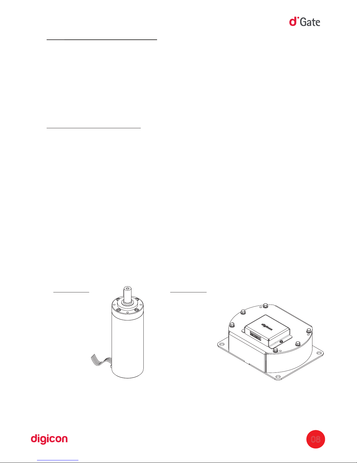
dGate uses the exclusive dPower , completely developed by Digicon with patentmotor
technology.
dPower allows controlled, smooth, silent, and comfortable turning for the user.
Some engine characteristics:
Robust;
Reliable;
High performance;
Electronicontrol;
Silent.
The
equipment has an operation mechanism activated by a permanent-magnets
engine, brushless type. The motor set is activated by direct current converted through
the activation of signals for later activation of the coil set.PWM
The engine is brushless-type, which is, the use of direct-current engines that use coal
as elements of its commuting system of magnet field is not accepted.
The equipment's activating mechanism (permanent-magnets brushless-type engine)
must be sealed and made of robust casing, with heat dissipation via natural or forced
convection; its mechanical elements, subject to supporting efforts, must be
permanently lubricated.
Voltage: 24Vdc
P
ower: 60W
Tork: 6,96Nm
Torque: <45dB
08
Motor SW
(swing gate)
Motor AW
(angel wing)
Voltage: 24 Vdc
Power: 72W
Tork: 17Nm
Torque: <20dB
Page 9
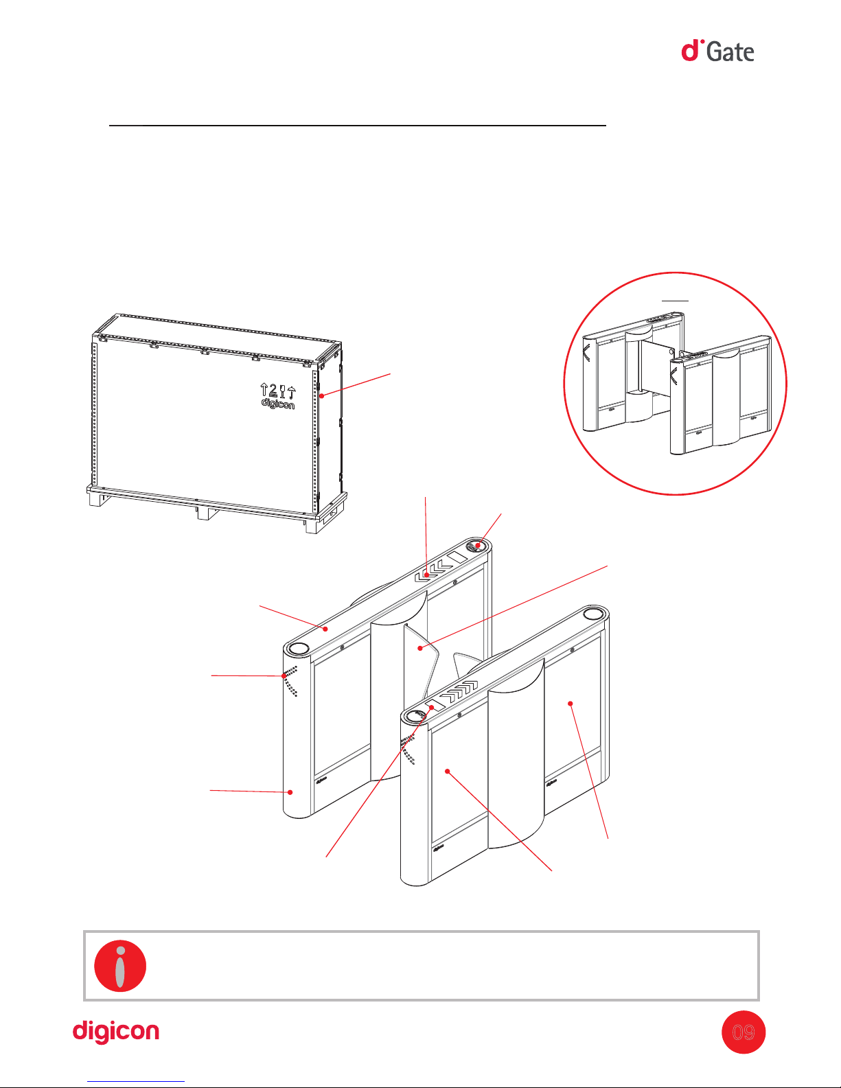
5.Installation and assembly:
5.1 Unboxing:
As the items inside the package can vary (depending on the client's requests), it is
important to perform a cautious visual inspection before installing and assembling the
turnstile. A checklist that works as a guide during inspection accompanies all Digicon
packages.
09
INFORMATION: The cover is configured according to commercial
combination.
Glass/polycarbonate
door (door-type
optional: or )AW SW
Collecting Box kit inlet
(optional)
Upper cover
(glass or stainless steel)
Orientation
pictogram
Access pictogram
(oper
ation)
Frontal or rear
column
Side doors for accessing
The equipment's
electronics and mechanism
Package
Display
(optional)
SW
Page 10
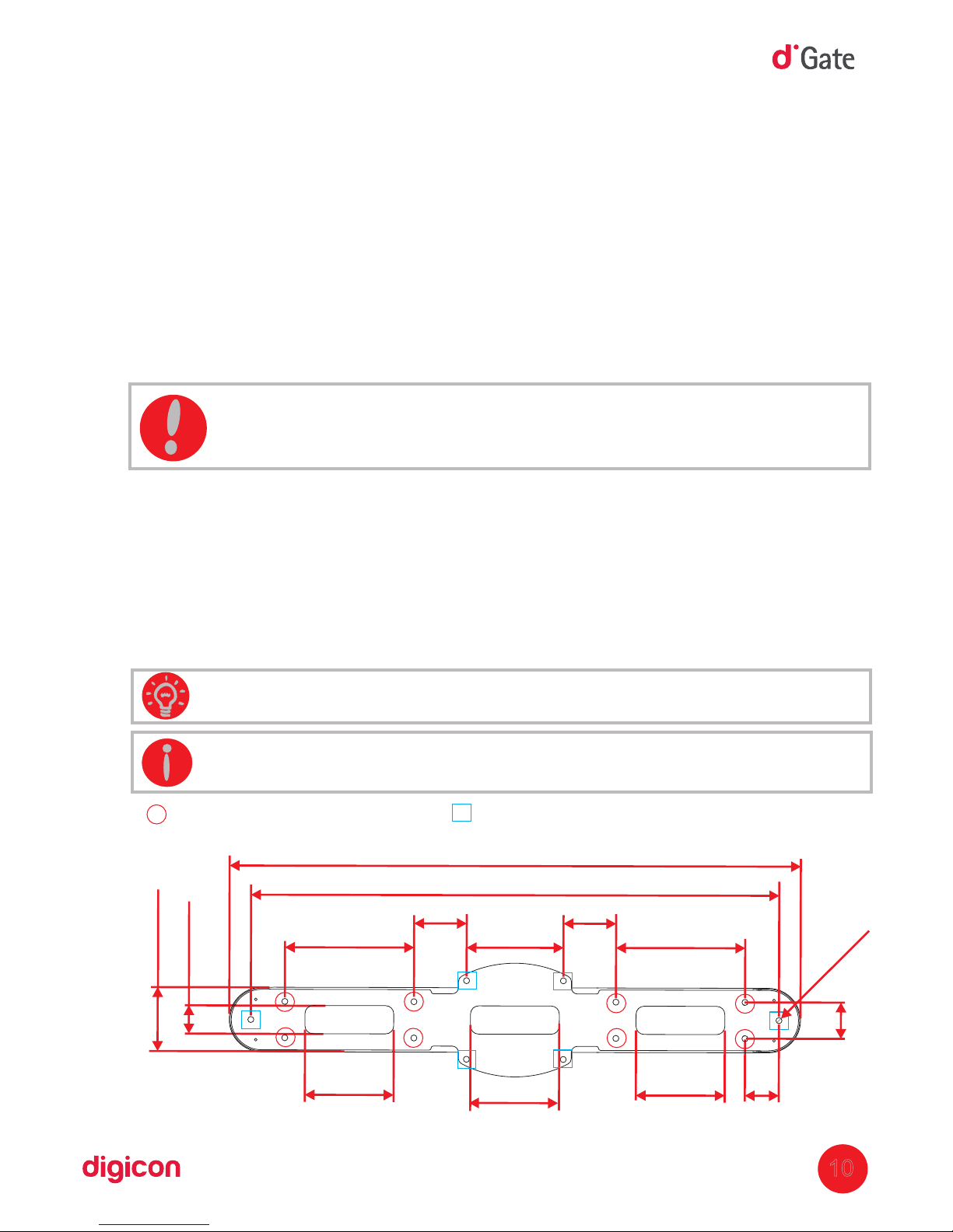
5.3 Fixing to the floor
The image below indicates the fixing points on the floor.
The surface must be steady and leveled to ensure good alignment of the sensors.
Fixing can be done through anchor bolts, also known as parabolts, through chemical
fixing.
5.2 Preparation for fixing
Before installing block , check:dGate
1. The place chosen for installing the equipment;
2. If there is a power source or electric sock
et nearby (ducts for connection).
3. If the place chosen is adequate for the installation of the access controller (indoors).
4. If the floor has conditions to receive anchor bolts (at least 4cm of 15 M.P.A.FCK
concrete or equivalent).
ATTENTION: Once the block dGate installation requires floor drilling, it is
extremely important that the place of installation be chosen carefully.
INFORMATION: Measures of the blocks dGate are illustrated in millimeters
and (Inches).
TIP: To fasten the screws, use a tool with a long extensor.
- Fixing points
10
Optional fixing points
70 (2.755")
1309(51.535")
1416
(55.748")
159 (6.259")
320
(12.598")
320
(12.598")
130
(5.118")
130
(5.118")
240(9.448")
Ø
15
(0.590")
90
(3.543")
84
(3.307")
220(8.661")
220(8.661")
220(8.661")
Page 11

11
With the holes for fixing the turnstile done, install the fixing tie rods according to the
image below. Digicon recommends using a capsule chemical anchorage by Hilti
( ).www.hilti.com.br
Step by step:
1. Using a 12mm drill, make a hole 90mm deep (tie rods M10).
2. Clean the hole with a blower or aspirator to remove the dust residue.
3. Place the tie rod inside the hole and measure the depth. The tie rod has a mark
that must remain parallel to the ground.
4. Place the capsule inside the hole.HVU
Page 12
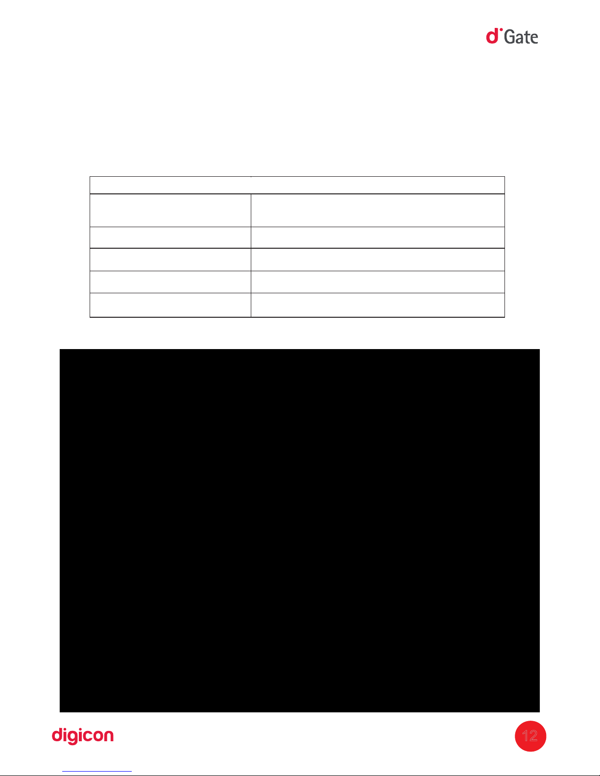
5. Secure the tie rod in the drill and screw it in until it reaches the bottom of the hole or
until the mark in the rod is leveled with the ground.
6. Apply the drill until the chemical material reaches the surface.
7. do not touch the tie rod to allow the chemical reaction (10 min).
8. curing time indicated in the table:
9.Tightening torque and other information can be seen in the following table:
12
Temperature of base material
Temperature of base materialCuring time necessary
until the fixing is able to receive the total load t
cure
20°C to 40°C
20 min
10°C to 19°
30 min
0° to 9°C
1 h
-5°C to -1°C
5 h
Data according to the -05/0255/0256/0257, edition 2010-03-01 / 2006-01-20ETA
Page 13
Resistences of calculation must be reduced for distances from the edge and spacing smaller than
the critical values.
a) h: base material thickness
b) This is the maximum tightening torque recommended to avoid rupture through cracking during
installation for fixings with minimal distance from the edge and/or spacing.
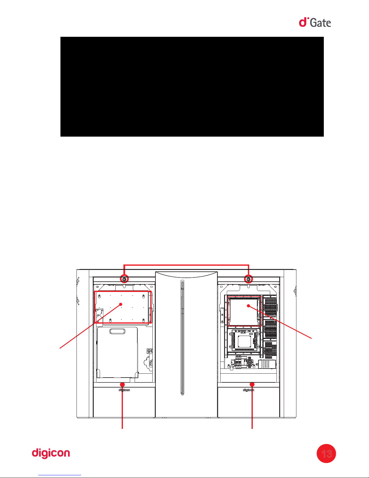
5.4 Access to block dGate after assembly:
After
the block dGate is installed and assembled, access to the interior of the
equipment can be done with the key that accompanies the equipment, in two ways:
Via the door that grants access to the electric panel;
Via the door that grants access to the engine or some accessory that is added, such
as the collecting box kit.
13
Locks
Electric panel door
Access door to
engine and accessories
Additional panel
for assembly of
inegrator’s access
controller
230x350mm
Additional panel
for assemblyof
(optional) orMCA
for the integrator’s
access controller
180x205mm
Page 14
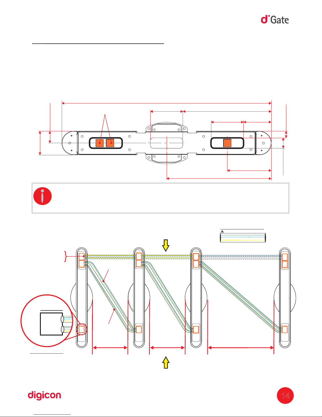
6.Power connection
14
1416(55.748")
188(7.401")
220(8.661")
598(23.543")
220(8.661")
45(1.771)
70(2.755")
298(11.732")
708(27.874")
160(6.299")
Embedded boxes
6.1 Interconnection of blocks
Below, you can see a template of the measures for installation of the embedded boxes,
which are installed before the block. There are two openings under the block, one on the
right and another one on the left, inside which the embedded boxes should be.
Conduits of
50 mm of diameter
920
520
520
Power network
Data cable
Power
network
cable
Interconnection
bo
xes
PASSAGE BOXES
Entry
Exit
Block seen from below:
4"x4"
INFORMATION:
The measures of block dGate are illustratein and (Inches),
I PNEn model, the block body measures 360mm of width.
80(3.149")
Page 15
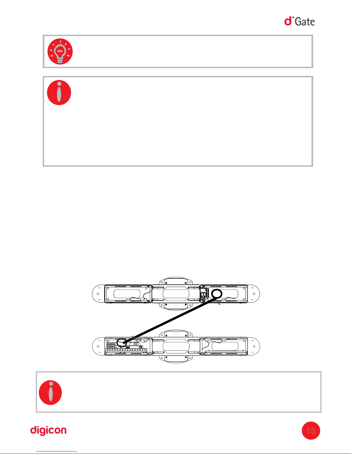
TIP: Separate the power network from the logic network.
15
INFORMATION:
Measures of block dGate are illustrated in millimeters.
There are three interconnection possibilities for the blocks: right side,
left side, and center.
The colors of the cables are illustrative only. The distance between the
passage
boxes vary according to the block size.
Basic cabling:
037.12.352 - Power cable sensors barrier Transmitter
037.12.355 - Power cable solenoid BOX
037.12.356 - Power cable Motor 2AC
037.12.357 - Communication cable 485 Motor 2RS
037.12.358 - Cable collecting box sensor
PNE:
037.12.445 -
Interconnection cable between blocks
INFORMATION:
Digicon offers 5-meter long interconnection cables.
The depth of the ducts must be measured so that the cables are long enough.
Page 16
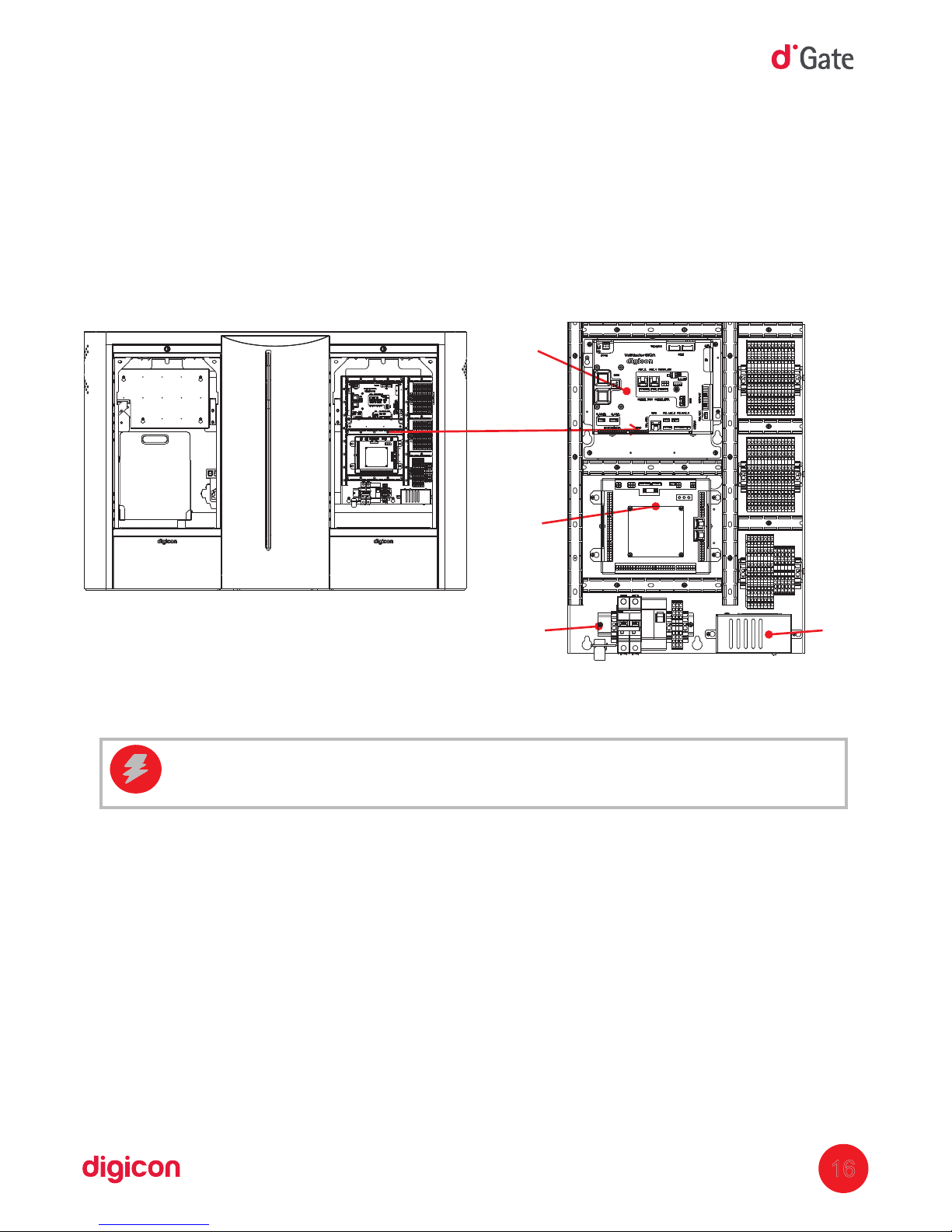
16
6.2 Electric panel
The electric panel presents the (Passage control Module), supplies (12Vcc), andMCP
control (Central processing unit). If the integrator requires more space, the blockCPU
has another area destined for it. In this area, there are the connections of the passage
sensors and power.
CAUTION: Risk of electric shock on the panel.
Panel
MCA
(optional)
Board
MCP
Borne
Supply
Set
Page 17
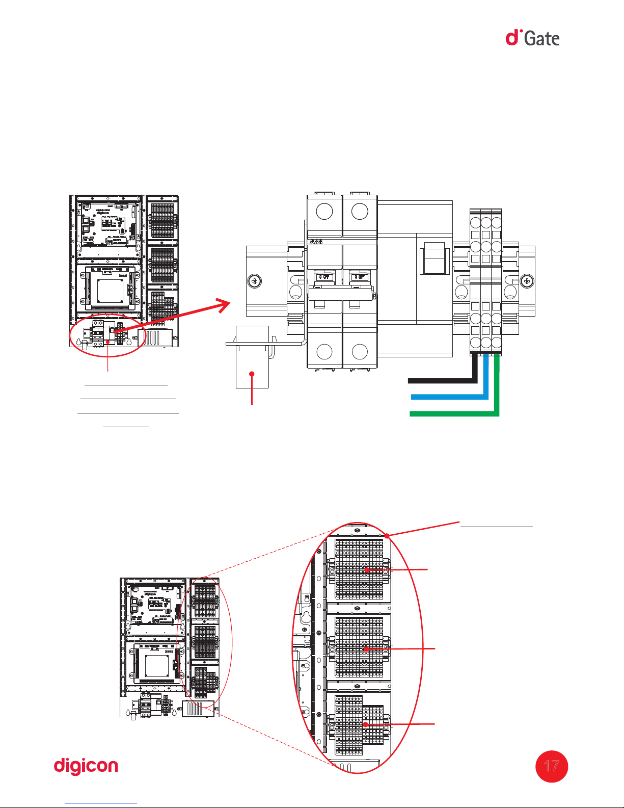
17
6.3 Electric power and logic supply:
The block dGate is fed with tension from to 240 Vca. Digicon recommends the90
regulation 5410 as reference to the equipment's electrical connections. In one ofNBR
its columns, the turnstile has a borne where the power cables (electrical supply) and the
ground wire must be connected.
6.4 Block interfacing
P
N
G
Born Set 02
Borne Set 01
- for connecting
electric and logic
network
Logic network
(used when the
turntile has board).
Borne 01 to borne 14
Borne 15 to borne 28
Borne 29 to borne 42
Page 18
NA
NA
NA
NA
UUUUU
UUUUU
NF
NF
C
C
Input
Input
Output
Output
(Integrator’s controlboard)
( )Panel's inner circuit
C
C
NA
UUUUU
NF
(Integrator’s controlboard)
Switch
18
1
2 3 4 5 6 7 8 9
10
11
12
1
3
14
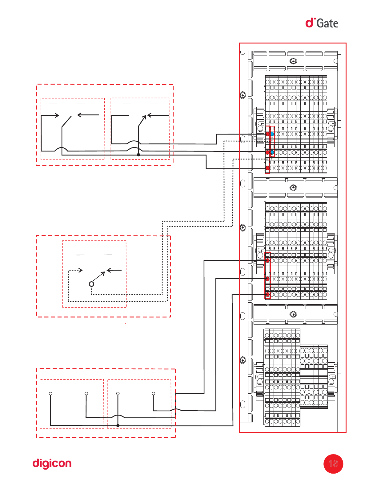
Enabling passage through dry contact (input):
Connection borne 02 borne 01
Switch (input):
Connection borne 02 borne 02 (optional)
Allows keeping block open leaving
The passage free in both directions
Con
firmation of passage through dry
contact (output):
Connection borne 02 borne 15
Page 19
7.Optional items
dGate is compatible with most access control technologies in the market today;
however, Digicon offers a range of optional items that allow enhancing and matching
the equipment's performance to the client's needs. See the description of each of
these items:
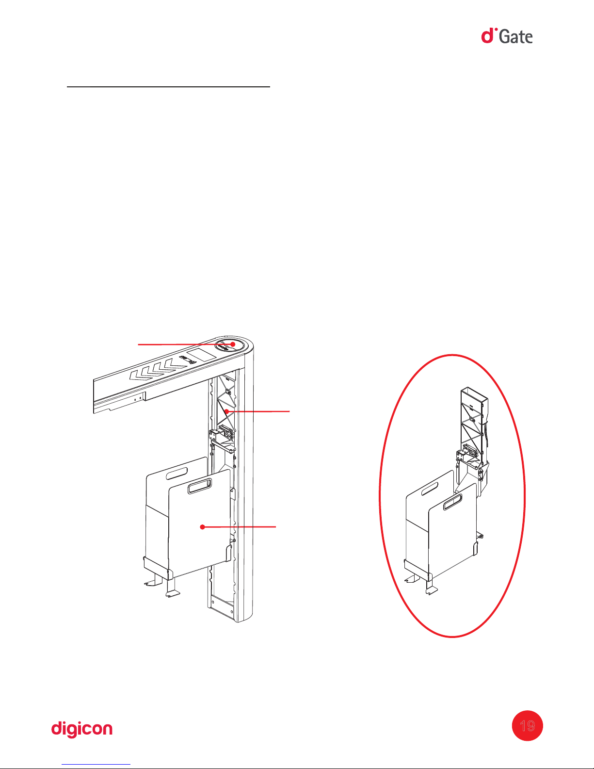
The collecting box kit has a device for collecting, retaining, and gathering cards or
badges. It is ideal for places with eventual visitors or users. The kit is composed of a
socket, a retention device activated by a solenoid, and a storage box.
The image below shows the items that accompany the collecting box kit and can
work as a guide for its assembly:
19
7.1 Collecting box kit
Box
Inlet
Collecting safe
Collecting box kit
Page 20
7.2 Pictograms
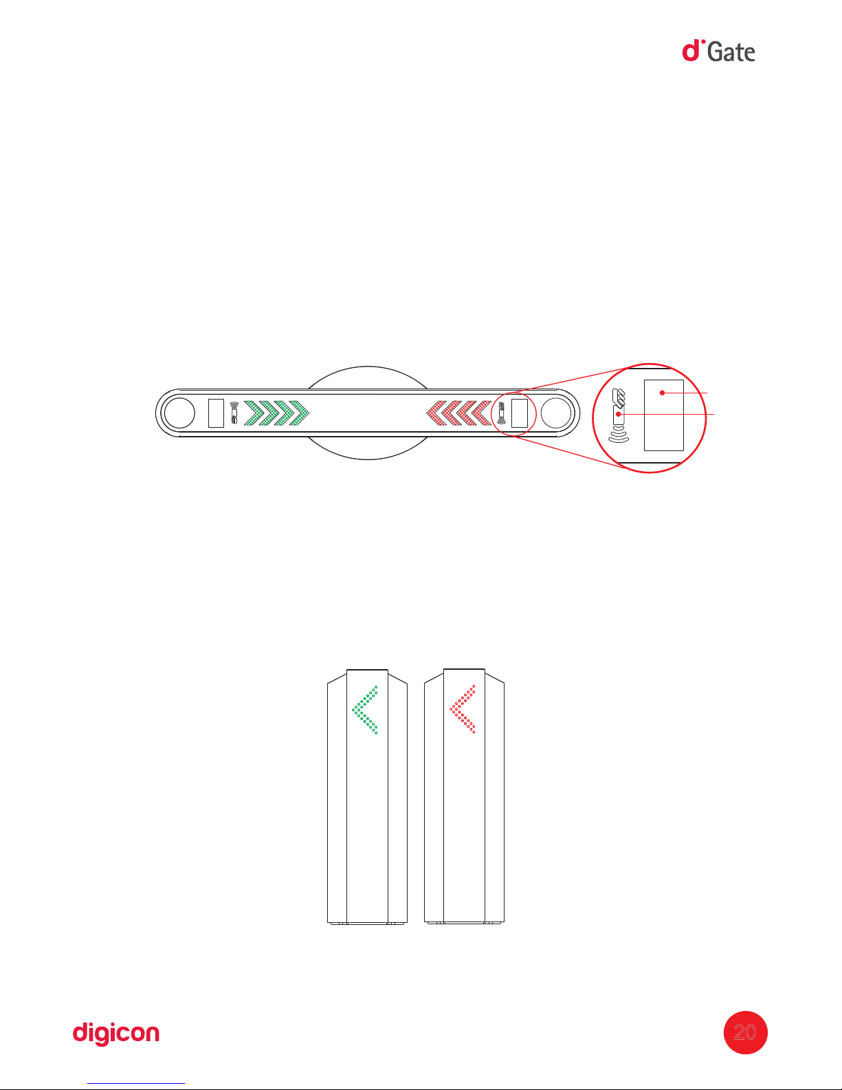
The block has two pictograms: Orientation and operation, the frontal pictogramdGate
(orientation) is integrated to the upper pictogram (operation) without electric
connection.
Operation pictogram (upper):
The operation pictogram is installed on the upper part of the equipment and is
represented by a red arrow and by a green arrow.
The red blinking pictogram, in both sides, means passage not allowed.
The green pictogram flows indicating direction means passage allowed.
Orientation pictogram (frontal):
The
orientation pictogram is installed on the edges of the equipment and is also
represented by red and green arrows.
The red pictogram informs the user that the block dGate is not operating in that direction
or that, at the time, passage is not allowed.
The green pictogram informs the user the direction in which block dGate is operating.
20
Pictogram
Pictogram
Direction ollowed or danied,
for example, when a user
clears the passage in the
opposite direction, flow is
denied.
Enable or disabled
direction, for example,
blockage can be
configured in only one
direction of passage
(entry only).
Display
Antenna
Page 21

21
Page 22
22
8. Sensors
Sensors are destined to detect the direction of the passage, user protection, and
detection of unauthorized passage.
8.1 barriers of sensors
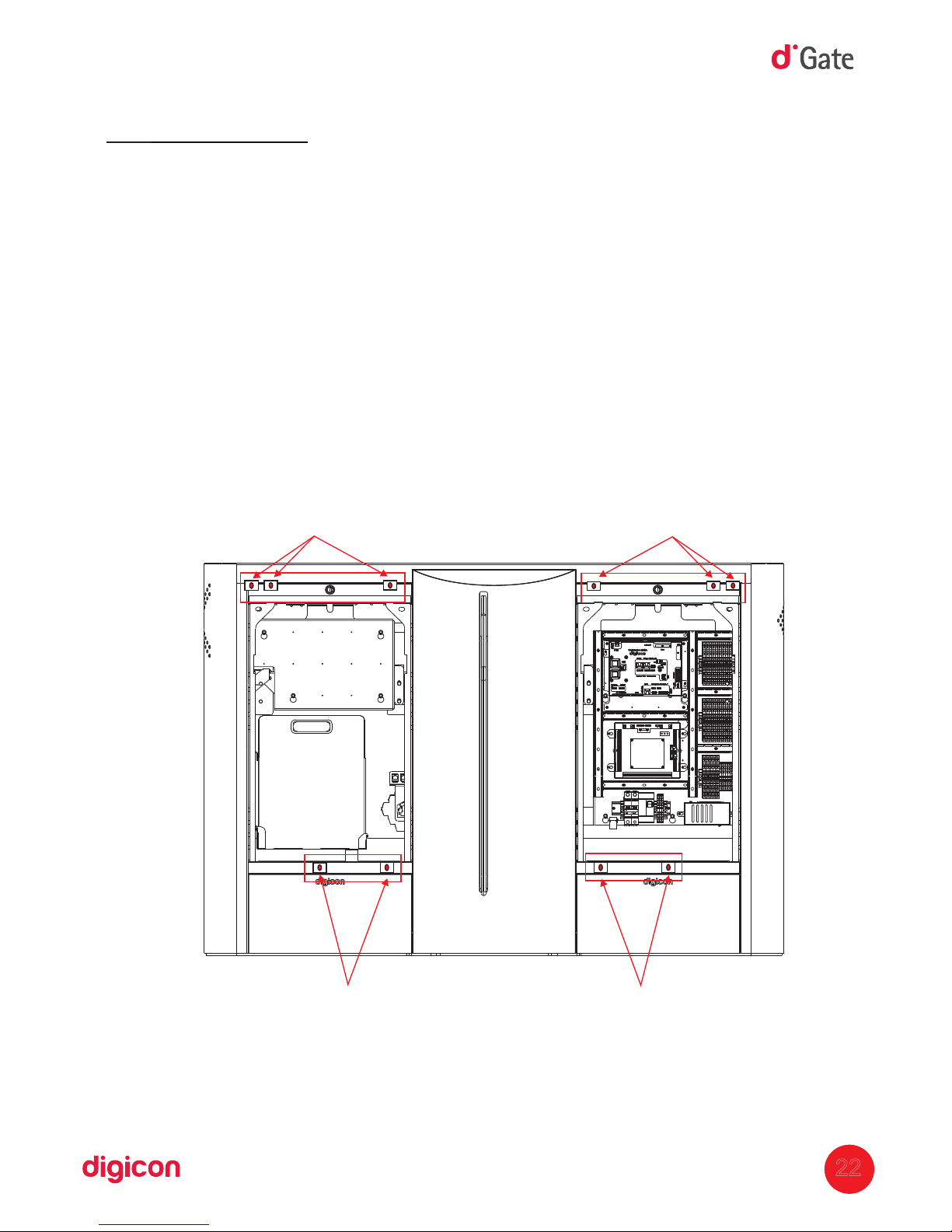
The block dGate has a total of ten infrared sensors (ten transmitters and ten receptors),
forming eight barriers that inform the module about the position of the pedestrianMCP
on the passage corridor. In the central area, there are two more sensors responsible for
the safety system (anti-crushing).
The detection system has twelve light-emitting sensors for detecting passage; two ofIR
these pairs (located in the central area, beside the door) are used for safety measures.
With them, it is possible to control the direction of passage (the system allows
directional operation) and it can be configured to operate in different passage
directions.
Localization of passage and safety sensors
Localization of passage and safety sensors.
Page 23
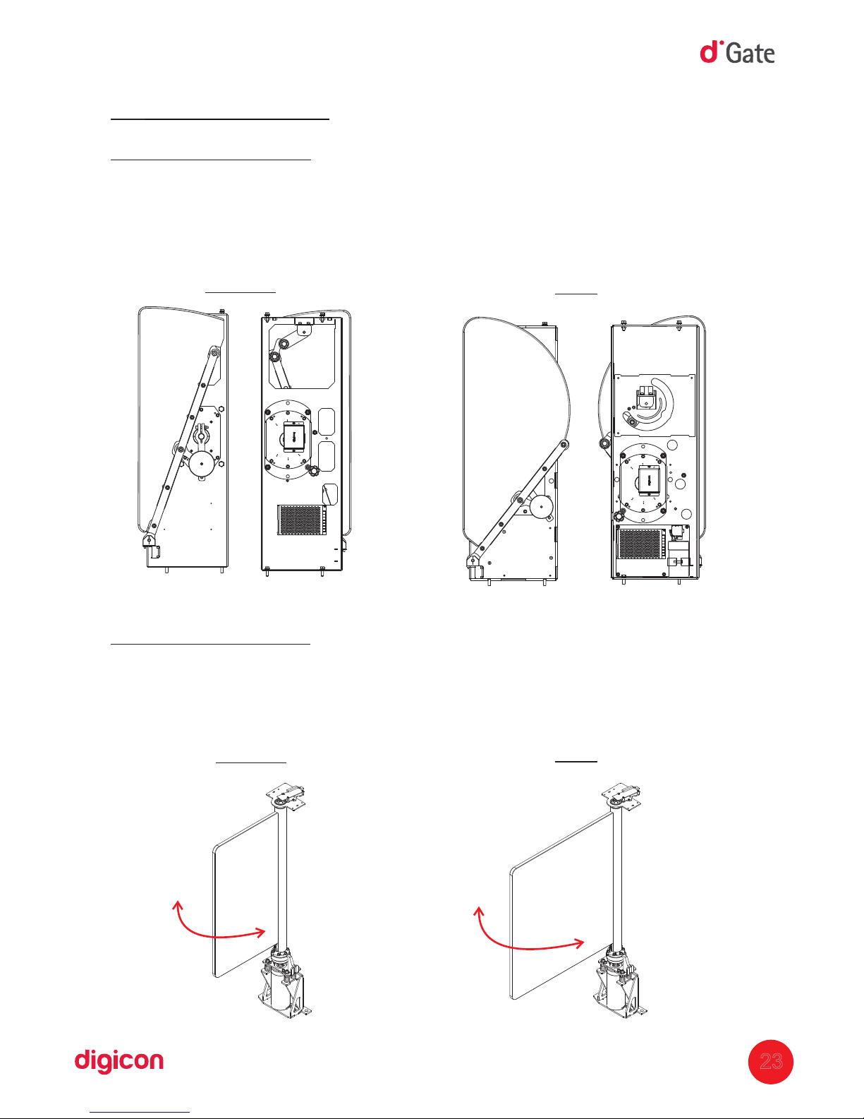
9.Anti-panic
Mechanism dGate :AW
The simple mechanism uses accumulated gravitational energy in a counterweight;
when the block is de-energized, the doors open. In the model for users with disabilities
( ), opening occurs via an electric system of temporary energy storage; when thePNE
block is turned off, the engine's control board open the wings.
Mechanism dGate :SW
When
the lock is de-energized the door is in the rest state (closed doors), butSW
unlocked, the user simply pushes the door in order to pass.
23
Simple
Simple
PNE
PNE
Page 24
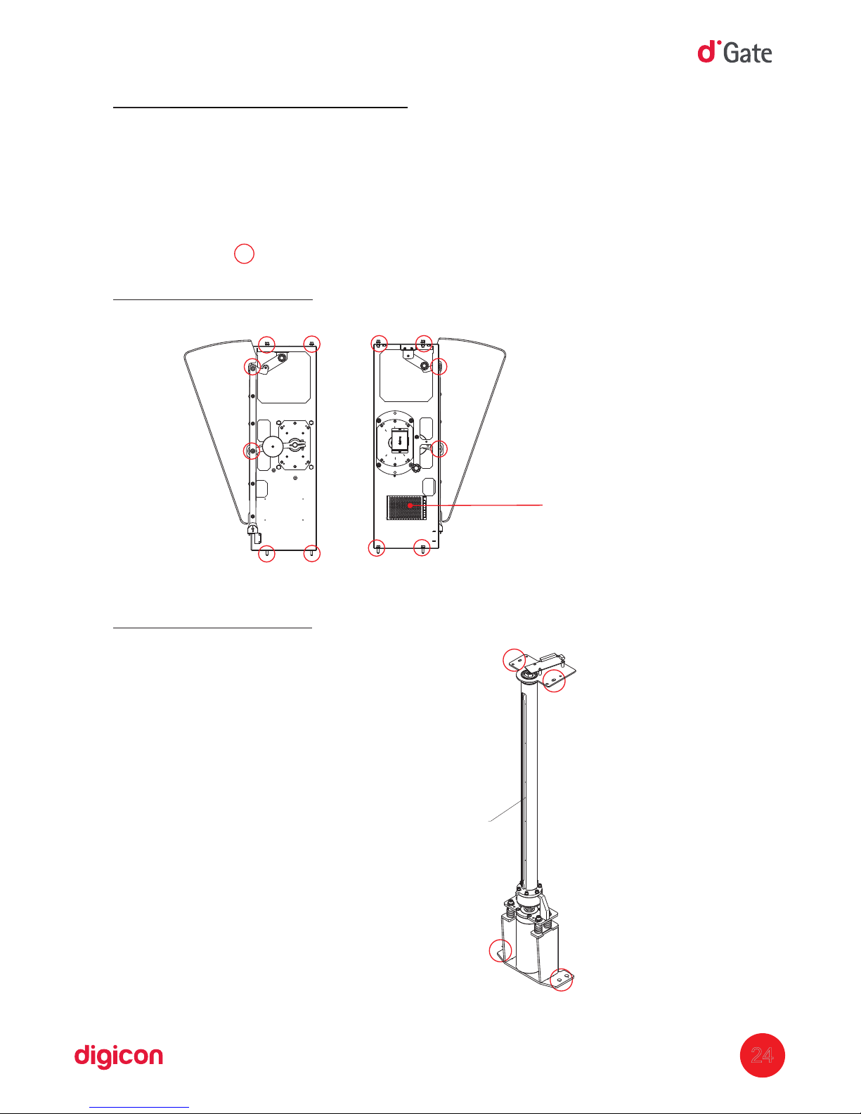
10. Maintenance
10.1 Door:
Check the support fixation of the wings every six months. This adjustment must be
performed with a torque wrench with value of 17 N.m.
Mechanism dGate :AW
Mechanism dGate
:SW
24
Fixing points:
Engine's power supply
Polycarbonate fixed according to
With the model 500 or 900
Page 25
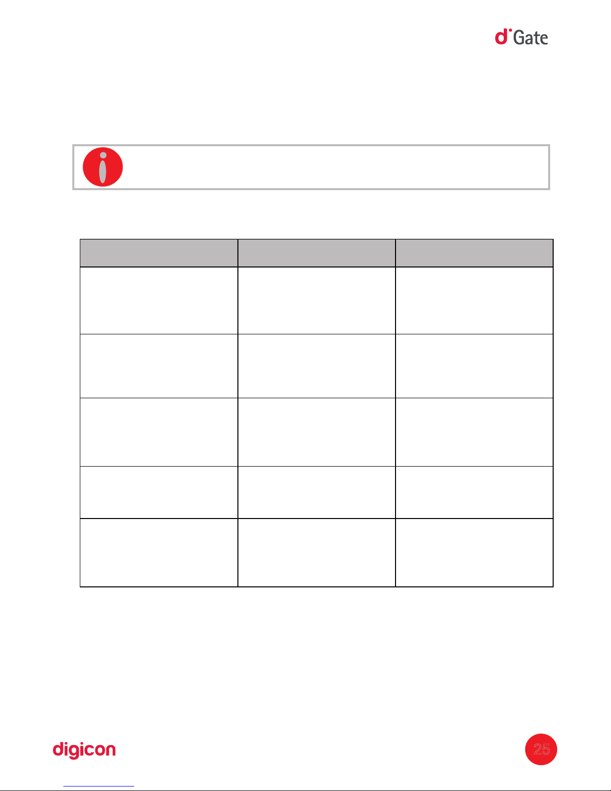
10.3 Defects and possible causes
Block dGate will not turn on.
Equipment is not receiving
power from the gridAC
or the circuit breaker is
turned off.
Check the circuit breaker and
the power network.
Sound alarm without
obstruction in the block.
Passage sensors
misaligned or their power
connection failure.
Check if the block is perfectly
aligned and then use the
MCP tester software to
identify the faulty sensor(s).
Pictograms do not turn on
alongside the display.
Lack of power in theAC
equipment, power failure,CC
open fuse in , brokenMCP
cables.
Check the grid, theAC MCP
fuse, and the cabling.
Pictograms display
wrong messages.
Display's data cable with
poor contact or connection
failure at the borne.
Check data cable and borne.
When enabling passage, the
doors open but not close
Check the sensors of the
blocks, because they can
consider that there is a user
in the turnstile.
Use the tester softwareMCP
to check the faulty sensor.
Then, perform realignment or
replace the sensor.
Problem
Possible causes
Action
25
INFORMATION: This maintenance routine requires the use of a vacuum.
10.2 Equipment cleaning:
Every six months, it is necessary to clean the block internally.
Page 26
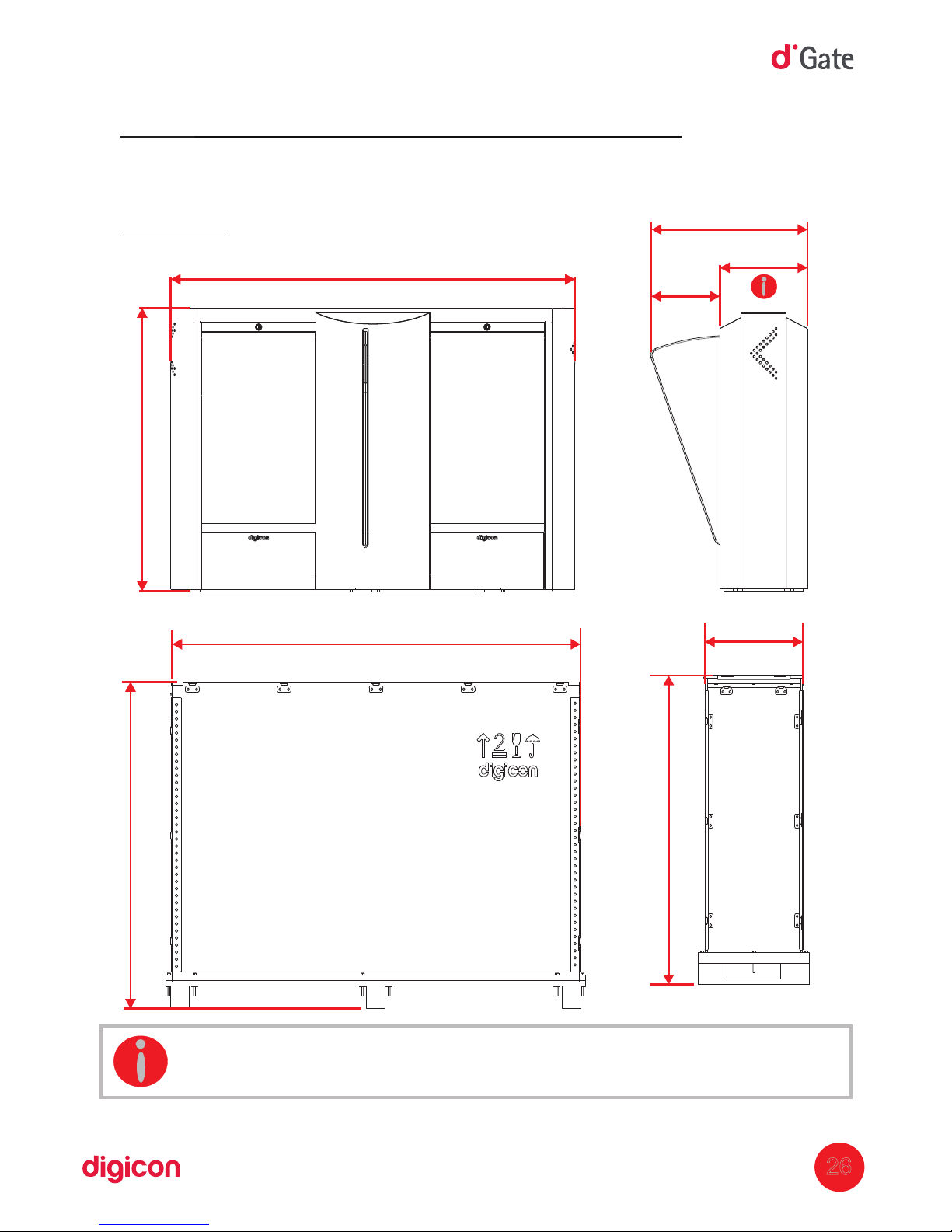
1416(55.748")
992(39.055")
312(12.283")
222(8.740")
534(21.023")
11. Technical characteristics
11.1 Dimensions:
INFORMATION: IN PNE models, the block's body measures 360mm of width.
26
1156(45.511")
1555(61.220")
442(17.401")
1156
(45.511")
dGate :AW
Page 27
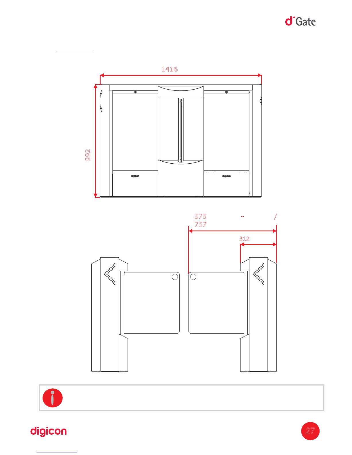
312(12.283")
575 - /(22.637") STD 500
757(29.803)- PNE 900
1416 (55.748")
992
(39.055")
27
INFORMATION: M andeasures of the block dGate are illustrated in millimeters
(inches).
dGate :SW
Page 28
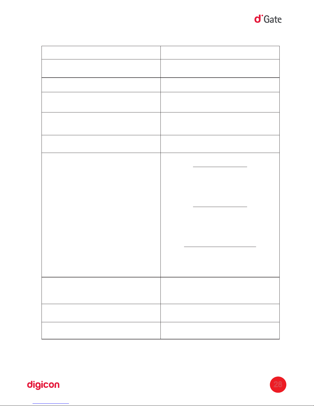
11.2 Other information
28
Technical data
100 - 240 Vca
( )Automatic selection
50 - 60 Hz
1 second
-5°C and 70°C
150 kg per packed
module
Power supply
Frequency
Average time for opening/closing the
door
Operational temperature
Weight
Consumption
Passage 500AW
Inicialization: 382W
Standby: 60W
Operation: 252W
Passage 900AW
Inicialization: 425W
Standby: 40W
Operacion: 403W
Passage 500/900SW
Inicialization: 36W
Standby: 32W
Operation: 92W
M capacity ofaximum
cards in collecting
120 cards
MTBF
(Mean time between failures)
MCBF
(Mean cy
cles between failures)
Higher than 10.000 hours
Higher than 500.000 cycles
Characteristics
Page 29

29
12.Warranty and Technical Assistance
Digicon is responsible for the project, skilled labor, and quality of the materials used in the
manufacturing of our products, ensuring that the equipment and all parts are free of
manufacturing defects or problems. Digicon commits itself to replace or repair, as we
choose, any part or equipment presenting manufacturing defects without any costs to the
buyer, in our factory in Gravataí or our branch office in São Paulo, in the conditions set
below:
1. The buyer is responsible for the costs of shipping (return service) of the product to the
factory in Gravataí or the branch office in São Paulo.
2. The warranty period is counted from the date of emission of the bill of sale and
encompasses:
a) 12 (twelve) months for equipment, accessories, parts, and pieces, including the legal
warranty period of 90 (ninety) days.
Legal warranty
The customer has the period of 90 (ninet
y) days, from the date of emission of the bill
of sale, to complain about apparent defects (easily observable in the product), such as
the items that constitute the product's exterior and any other area accessible to the
user, just like appearance parts and general accessories.
b) 90 (ninety) days for repairs or technical assistance
3. Warranty shall be granted to the buyer only in the face of the bill of sale (original or
copy)
4. Warranty does not apply in the following cases or conditions:
a) defects and damages caused by accidents, negligence, or reasons of force majeure
b) defects and damages caused by inappropriate storage or lack of prolonged use
c) defects and damages caused by improper use of the equipment
d) defects and damages caused by improper operation or installation of the equipment
e) vandalism
f) natural impacts (lightning, flooding, etc.)
g) defects and damages caused by abnormal temperature conditions,
voltage/frequency, or humidity out of the levels specified in the installation and
operation manual, once proven
h) reconditioning, chrome plating, nickel plating, and painting
5. Warranty shall be automatically canceled for equipment that:
a) suffers modifications, adaptations, or an
y alterations performed by the client or by
third parties without Digicon's written consent
b) goes through maintenance or repairs by people not authorized by Digicon
c) suffers alteration of serial number or violation of the identification label
d) is not paid for in the conditions, amounts, and deadlines described in the bill of sale
6. Digicon is not responsible for eventual losses suffered by the down time of the
equipment
7. The repair of a warranted product will be performed inside the Digicon facilities.
Page 30

Page 31

Page 32
Head office/RS
Factory, Technical Assistance, and Sales
Development, Technical Assistance, and Sales
Street Nissin C
astiel, 640 - Distrito Industrial.
Gravataí/ 94045RS CEP -420
Sales: (0xx51) 3489.8700 / 3489.8745
Technical assistance: (0xx51) 3489.8903
E
mail: [email protected]
Branch office/ SP
Street São Paulo, 82
- Alphaville.
Barueri/ 06465SP CEP -130
Sales: (0xx11) 3738.3500
Email: [email protected]
Home page: www.digicon.com.br
 Loading...